![]()
![]()
USER MANUAL
Smart LED dimmer Z-Wave 0-200W
Eco-Dim.07 Z-Wave
Please Read this manual Carefully before installation.
Important!
- It is dangerous if people without proper training work on an electrical installation!
- There may be a dangerous voltage at the output of the dimmer!
- When working on the wiring always switch off the mains voltage. Failure to observe this warning may result in death or serious injury!
- Read the instructions carefully. Incorrect installation may damage the dimmer beyond repair.
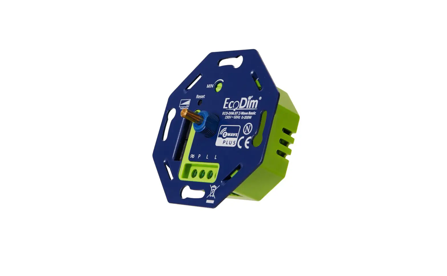
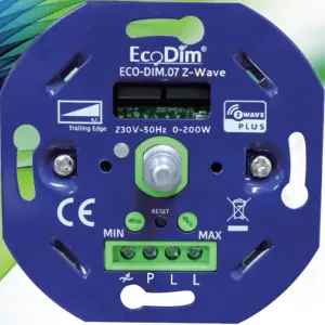
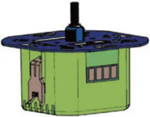
Smart Dimmer Switch 200W LED
Item NO. Eco-Dim.07 Z-Wave
![]()
![]()
![]()
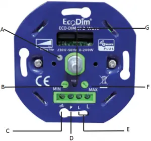
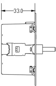
A. LED Indicator
Indicates resets and when the dimmer is in pairing mode
B. Min. Setting
To set the minimum light level.
C. 220-240V AC Output
D. Optional: to connect extra Push Buttons
E. 220-240V AC Intput
F. Max. Setting
To set the maximum light level.
G. Reset Button
To set the dimmer to factory settings or to pair mode.
![]() Compatible with any Z-Wave or Z-Wave plus controller.
Compatible with any Z-Wave or Z-Wave plus controller.![]() Power Consumption meter
Power Consumption meter![]() Voice support (Amazon Alexa & Google Assistant / Homey)
Voice support (Amazon Alexa & Google Assistant / Homey)![]() Achieve the on/off and dimming function through separately physical button
Achieve the on/off and dimming function through separately physical button![]() Support Repeater Role, Firmware OTA and SmartStart.
Support Repeater Role, Firmware OTA and SmartStart.![]() Suitable for 0-200W LED
Suitable for 0-200W LED![]() Suitable for all well-known brands of cover frames
Suitable for all well-known brands of cover frames![]() Optimal dimmable & light stability
Optimal dimmable & light stability![]() MIN and MAX light adjustment options
MIN and MAX light adjustment options![]() Suitable for 90% of all LEDs
Suitable for 90% of all LEDs![]() Installation with provided 2 wires (no neutral wire required)
Installation with provided 2 wires (no neutral wire required)![]() Soft start system
Soft start system![]() Noiseless dimming
Noiseless dimming![]() Suitable for surface-mounted boxes & flush-mounted boxes with or without screw holes
Suitable for surface-mounted boxes & flush-mounted boxes with or without screw holes
3
1. Specifications
Input voltage 220-240 Vac, 50Hz
Power (load) 0-200W LED, 10-300W Halogen light bulbs
Suitable for Led-, halogen-, light bulbs
Type dimmer R, C Phase cut
Working temperature 35 °C
Operation Push / turn button
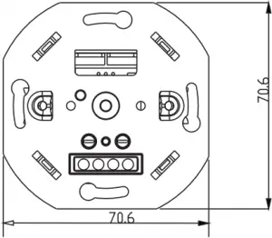
Dimensions 70.6×70.6x33mm
Weight 49,98g
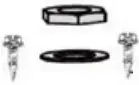
Suitable brands of cover material:![]() Berker by Hager
Berker by Hager![]() Busch-Jaeger
Busch-Jaeger![]() Gira
Gira![]() JUNG
JUNG![]() Kopp
Kopp![]() Merten by Schneider
Merten by Schneider![]() Niko
Niko![]() PEHA
PEHA
![]()
![]() _________ only use for Busch-Jaeger
_________ only use for Busch-Jaeger
 ____ only use for Jung
![]()
![]() _______ use for Busch-Jaeger and Niko
_______ use for Busch-Jaeger and Niko
4
2. Installation
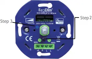
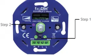
Step 1: Remove the knob and the cover plate.
Step 2: Always make sure that the electricity is switched off during installation. Then connect the wires as indicated in the ‘Connection diagram’.
Step 3: Now install the dimmer in the mounting box. Use screws or tighten the screws of the mounting clamps.
Step 4: Switch the electricity back on. Switch on the connected lights by pressing the dimmer shaft. Now adjust the ‘MIN/MAX adjustment, as described under ‘MIN/MAX installation’
Step 5: Optionally you may connect the dimmer to your SMART home system as indicated under the heading “Connecting home automation / apps”.
Step 6: Place back the cover plate and dimmer knob.
3. MIN/MAX adjustment
For the SMART dimmer to work optimally, you can adjust the lights to the dimmer with the MIN and MAX adjustment. As soon as you start turning MIN and MAX adjustment, the dimmer will automatically go to the minimum and maximum light range.
MIN adjustment: Switch on the lights with the push / turn button. When the lights are on, insert a screwdriver in MIN and turn to the left. When the light becomes unsteady, turn slightly back to the right so that the light remains steady.
MAX adjustment: Switch on the lights with the push / turn button. When the lights are on, insert a screwdriver in MAX and turn to the right. When the light becomes unsteady, turn slightly back to the left so that the light remains steady.
5
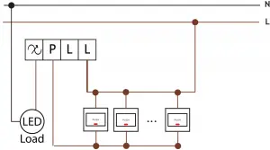
4. Connection diagram
1) One Way Connection
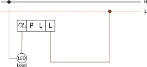
2) Multiway master& slave wiring connection
6
5. Operation
1) SmartStart Inclusion
Smart Start enabled products can be added into a Z-Wave network by scanning the Z-Wave QR Code present on the product with a controller providing SmartStart inclusion. No further action is required and the Smart Start product will be added automatically within 10 minutes of being switched on in the network vicinity.
- Add the dimmer controller DSK into the primary controller SmartStart Provisioning List. (If your controller does not support SmartStart inclusion, please refer to the manual for your controller for non-SmartStart inclusion.).
- Power cycle once for dimmer controller.
- The dimmer controller will send “Explorer Auto inclusion” frame to start SmartStartInclusion.
- Wait a moment, the dimmer controller should be added to the controller.
Note: The dimmer controller will SmartStart Inclusion when it is removed from a Z-Wave network.
The Dimmer has a DSK string, you can key in first five digit to increment SmartStart process, or you can scan QR code. The QR code can be found on the Dimmer controller or in the box.
Ex: 65286-19008-32952-20593- 44872-18102-41266-46651
2) Inclusion to a Z-Wave Network
Step 1. Remove the device from previous Z-Wave network if it has already been added to, otherwise pairing mode will be fail.
Step 2. Double Press the reset button.
Step 3. The indicator will start blinking blue and stay solid for 10s when pairing succeed, timeout 15mins.
7
3) Remove from a Z-Wave Network
Method 1. From your Z-Wave hub interface, choose to delete or reset the device as instructed.
Method 2. Remove from the Device, see below instructions.
Step 1. Press the reset button for 3 times.
Step 2. The indicator will start blinking purple and stay solid for 10s when remove done, timeout 3mins.
4) Factory Reset
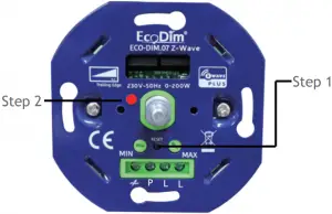
Step 1. Press the reset button for 5s.
Step 2. When the Indicator stay in Red for 10s, reset finished.
Please Note:
This procedure should only be used when the primary controller is inoperable.
All configurations will be reset after the device is reset or remove from the network.
8
3. Note for special commands
1) Z-Wave plus Info Command Report
| Parameter | Value |
| Z-Wave Plus Version | V1 |
| Role Type | ZWAVEPLUS_INFO_REPORT_ROLE_TYPE_SLAVE_ALWAYS_ON |
| Node Type | ZWAVEPLUS_INFO_REPORT_NODE_TYPE_ZWAVEPLUS_NODE |
| Installer Icon Type | ICON_TYPE_GENERIC_LIGHT_DIMMER_SWITCH |
| User Icon Type | ICON_TYPE_GENERIC_LIGHT_DIMMER_SWITCH |
2) Association Group Info Command
Association is different to Inclusion. The Inclusion function of a device “includes” the device into a network, allowing it to communicate with other network devices. The association function “associates” two devices, enabling them to communicate directly without the need for a central controller.
a) Association Group Name Command Report
| Association Groups | Group Name | Max Nodes | Description |
| Group 1 | Lifeline | 5 | The ASSIC of Lifeline: 4C 69 66 65 6C 69 6E 65 1. When press and hold down “Reset” button for 4S to reset the dimmer, send “Device Reset Locally Notification CC” to associated devices of this group to report factory reset information. 2. When load state changes, send “Switch Multilevel Report CC” to associated devices of this group. |
| Group 2 | Basic Set | 5 | Basic Set: 42 61 73 69 63 20 53 65 74 1. Short press the knob turn on the dimmer Sends Basic Set(0xFF) to associated devices 2. Short press the knob turn off the dimmer Sends Basic Set(0x00) to associated devices |
| Group 3 | Switch Multilevel | 5 | Switch Multilevel: 53 77 69 74 63 68 20 4D 75 6C 74 69 6C 65 76 65 6C 1. “Anti-Clockwise the knob” Sends Switch Multilevel Set(to decrease the brightness and keep associated devices in sync with this device) to associated devices 2. “Clockwise the knob” Sends Switch Multilevel Set(to increase the brightness and keep associated devices in sync with this device) to associated devices |
| Group 4 | External Button | 5 | External Button: 45 78 74 65 72 6E 61 6C 20 42 75 74 74 6F 6E 1. External Button hold send Switch Multilevel Start Level Change (Switchover dimmer Up/Down) 2. External Button release send Switch Multilevel Stop Level Change |
b) Association Group Info Command Report
| Parameter | Team No. | Value |
| Profile | Group 1 | General: Lifeline, Profile MSB=0x00,Profile LSB=0x01 |
| Profile | Group 2 | General: Lifeline, Profile MSB=0x20,Profile LSB=0x01 |
| Profile | Group 3 | General: Lifeline, Profile MSB=0x20,Profile LSB=0x02 |
| Profile | Group 4 | General: Lifeline, Profile MSB=0x20,Profile LSB=0x03 |
c) Set and unset associations
(Note: All association information will be cleared automatically once the dimmer is excluded from a network.)
The primary controller/Gateway send packets to the dimmer using “Command Class ASSOCIATION”
d) Association Group Command List Command Report
| Team No. | Command List Support | |
| Group 1
| COMMAND_CLASS_SWITCH_MULTILEVEL (0x26) | SWITCH_MULTILEVEL_REPORT (0x03) |
| COMMAND_CLASS_DEVICE_RESET_LOCALLY(0x5A) | DEVICE_RESET_LOCALLY_NOTIFICATION(0x01) | |
| Group 2 | COMMAND_CLASS_BASIC(0x20) | BASIC_SET(0x01) |
| Group 3 | COMMAND_CLASS_SWITCH_MULTILEVEL(0x26) | SWITCH_MULTILEVEL_SET(0x01) |
| Group 4 | COMMAND_CLASS_SWITCH_MULTILEVEL(0x26) | SWITCH_MULTILEVEL_SET(0x01) |
4) Basic Command
Basic CC is maps to Multilevel CC
Basic Set = 255 maps to Multilevel Switch Set = 255
Basic Set = 0 maps to Multilevel Switch Set = 0
Basic Set = 1-99 maps to Multilevel Switch Set = 1-99
Basic Get/Report maps to Multilevel Switch Get/Report.
5) Configuration Command Parameters
The Dimmer offers a wide variety of advanced configuration settings. Below parameters can be accessed from main controllers configuration interface.
| Parameter | Size | Default Value | Description |
| 1 | 1 | 00 | State After Power Restored: The state the switch should return to once power is restored after power failure. 0 – Off. 1 – On. 2 – Returns to level before Power Outage |
| 2 | 1 | 01 | Notification when Load status change: The Dimmer will send notification to associated device (Group Lifeline) when the status of Dimmer load is changed. 0 – The function is disabled. 1 – Send Switch Multilevel Report. |
| 3 | 1 | 05 | Default dimming speed,unit is second. Valid value:0-100 0 – Instanly. 1 – Fast. … 100 – Slow. |
| 5 | 1 | 0 | Enable or Disable external switch to pair network. 0 – Disable. 1 – Enable. |
| 6 | 1 | 0 | Setting dimming way. 0 – Linear dimming. 1 – Logarithmic dimming. |
| 7 | 1 | 0 | Setting default brightness when turn on the dimmer from off status. Setting of 0 means that the dimmer will use parameter 1. Valid value:0-99 |
| 8 | 1 | 0 | Setting delay time when turn off, unit is second. Valid value:0-60 |
You can find the full list of Z-wave commands on our website. www.ecodim.nl/downloads-smart-dimmer
![]()


EcoDim
Dr. Huber Noodtstraat 89
7001DV Doetinchem
[email protected]
+31 (0)314 844691


