Z-WAVE PLUS RGBW Color LED Dimmer User Manual
Introduction
The RGBW Controller is a universal, Z-Wave compatible RGB / RGBW controller. The RGBW Controller uses PWM output signal, which enables it to control LED, RGB, RGBW strips, Halogen lights. Controlled devices may be powered by 12 or 24 VDC. All IN and OUT terminals can be configured for LED control.
Package Contents
- R.G.B.W. Color LED Dimmer x1
- 3M Double-sided Adhesive Sticker x1
- User Manual x1
- 18AWG copper wire x1
- Conductive connector x1
Command Class
Multilevel Switch Device Information
GENERIC_TYPE_SWITCH_MULTILEVEL
SPECIFIC_TYPE_POWER_SWITCH_MULTILEVEL
Multilevel Switch Command Class
- COMMAND_CLASS_ZWAVEPLUS_INFO_V2
- COMMAND_CLASS_VERSION_V2
- COMMAND_CLASS_MANUFACTURER_SPECIFIC_V2
- COMMAND_CLASS_DEVICE_RESET_LOCALLY,
- COMMAND_CLASS_POWERLEVEL_V1
- COMMAND_CLASS_BASIC_V1
- COMMAND_CLASS_SWITCH_MULTILEVEL_V2
- COMMAND_CLASS_SWITCH_COLOR_V2
- COMMAND_CLASS_CONFIGURATION_V1
- COMMAND_CLASS_ASSOCIATION_V2
- COMMAND_CLASS_ASSOCIATION_GRP_INFO_V1
- COMMAND_CLASS_SWITCH_BINARY_V1
- COMMAND_CLASS_FIRMWARE_UPDATE_MD_V2
Detailed description of each command class
ZWAVEPLUS INFO command class
The Z-Wave Plus Info Get Command is used to get additional information of the Z-Wave Plus device in question.
BASIC command class
The module will be turned ON or OFF after receiving the BASIC_SET command.
To be turned on:
[Command Class Basic , Basic Set, Basic Value = 0x01~0x63 in percentage; FF set to last value]
To be closed:
[Command Class Basic , Basic Set, Basic Value = 0x00]
SWITCH MULTILEVEL command class
The module will be turned ON or OFF after receiving the SWITCH_ MULTILEVEL_SET command.
To be turned on:
[Command Class Multilevel , Multilevel Set, Basic Value = 0x01~0x63 in percentage; FF set to last value]
To be closed:
[Command Class Multilevel , Multilevel Set, Basic Value = 0x00]
SWITCH COLOR command class
This class is used for Color setting. See the following table for configuration variables:
| Capability ID | Color | State Level |
| 0 (0x00) | Warm White | 0x00-0xFF |
| 2 (0x02) | Red | 0x00-0xFF |
| 3 (0x03) | Green | 0x00-0xFF |
| 4 (0x04) | Blue | 0x00-0xFF |
DEVICE RESET LOCALLY command class
The Device Reset Locally Command Class is used to notify central controllers that a Z-Wave device is resetting its network specific parameters.
VERSION command class
The user can enquire the version of the unit using VERSION_GET command. It will return VERSION_REPORT Command.
Version Report Command:
[Command Class Version, Version Report, Z-Wave Library Type, Z-Wave Protocol Version, Z-Wave Protocol Sub Version, Application Version, Application Sub Version]
MANUFACTURER SPECIFIC command class:
The user can use the Manufacturer Specific Get Command to request manufacturer specific information from another node.
Manufacturer Specific Report Command:[Command Class Manufacturer Specific, Manufacturer ID 1, Manufacturer ID 2, Product Type ID 1, Product Type ID 2, Product ID 1, Product ID 2]
CONFIGURATION command class
This class is used for setting certain vendor specific configuration variables. See the following table for configuration variables:
| ID | Name | Size | Range | Default value | Description |
| 2 (0x02) | Switch mode | 1 byte | 1-3 | 1 | 1: Normal Mode 2: Brightness Mode 3: Rainbow Mode |
| 3 (0x03) | Auto Scene Mode Set | 1 byte | 1-5 | – | 1: Ocean 2: Lightning 3: Rainbow 4: Snow 5: Sun |
| 4 (0x04) | Auto Scene Mode Duration | 1 byte | 0x03- 0xFE | 3 | Adjust Scene delay time: 1. When Value is 1(0x01)~127(0x7F), the delay duration is 1 sec.~127 sec. 2. When Value is 128(0x80)~255(0xFE), the delay duration is 1 min.~127 min. |
ASSOCIATION command class
The Module can be set 1 auto-report ID in Group 1. The Module will send BASIC_REPORT to device associated in Group 1 when correspond Device is activated.
FIRMWARE UPDATE META DATA command class, version 2 Support OTA (On-The-Air) firmware update function.
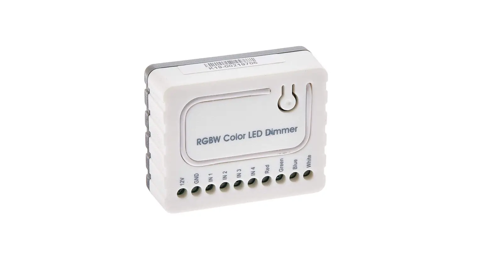
Product Overview
Device Installation
- Prepare the following items:
RGBW strip(12V or 24V) x1
Stranded wire x5
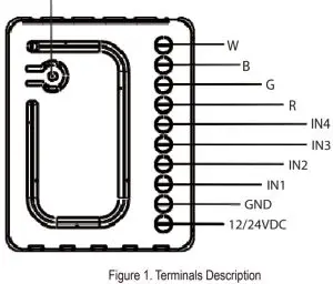
Power adapter x1 - Figure 1. Terminals Description.

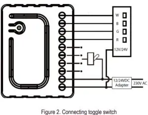
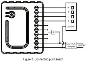
Include/Exclude Button - Connect the R.G.B.W. Color LED Dimmer according to Figure 2., or Figure 3. First, connect RGBW strip with output channel(R,G,B,W) Second, connect the power supply. If the device is properly connected, the RGBW strip will blink once. Note that the device must be powered by a dedicated stabilized power adapter.


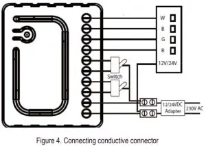
- According to the Figure 4.,you can use the 18AWG copper wire and conductive connector to extend the connection of the power supply.
- In the status of the factory default (Not Paired), the red light and green light will blink by turns, eg. red, green, red, green, etc..
- Include the R.G.B.W. Color LED Dimmer into the Z-wave network, press 3 times in 2 seconds. If the device is properly included, the green light will remains on.
- Exclude the R.G.B.W. Color LED Dimmer into the Z-Wave network, press 3 times in 2 seconds. If the device is properly excluded, the green light will blink and the data will be reset to the factory default values.
- Please pull out the antenna and keep it at 90 degree to enhance the RF signals.
- Support auto inclusion: Install the device, connect with the power, and the auto inclusion function will work in about 2 minutes.
- Support remote exclusion: Through configuration setting.
Please refer to the following table.ID Size Value F0 1 byte 1
Warning!
- The RGBW Controller is suggested to operate in low voltage circuits of 12VDC or Connecting higher voltage load may result in the RGBW Controller damage.
Please refer to the following table.Current of RGBW Strip Stranded Wire High current 18 AWG Low current 22 AWG - The RGBW Controller must be powered by the same voltage as the connected light source. I.e. if controlling 12V LED strip, the module must be connected to 12V power supply. Similarly, if controlling 24V RGBW strip, the RGBW Controller must be powered by 24V voltage supply.
- The RGBW Controller must be powered by 12VDC or 24 VDC stabilized power supply with outputs load capacity matched to loadsvoltage.
- In case of connecting long RGBW/RGB/LED strips voltage drops may occur, resulting in lower light brightness further from R/G/B/W outputs. To eliminate this effect it’s recommended to connect few shorter strips in parallel connection instead of one long strip connected serially. Maximum recommended wire length, used to connect R/G/B/W outputs with a RGBW/RGB/LED strip is 5 m. Observe connected loads manufacturer recommendations towards connection wire diameter.
- For connection of IN1~IN4, it is suggested that you connect the 4 inputs individually to the same type of deivce. The devices can be as follows: the toggle switch, or the push switch.
- Please note that re-including the product will reset the data to the default values. Use this procedure only in the event that the network primary controller is missing or otherwise inoperable.
Glossary of terms
Include/Exclude Button – Inclusion/exclusion, press 3 times in 2 seconds
| 12/24VDC – Power supply signal | IN4 – Switch input 4 |
| GND – Power supply ground signal | R – Output assigned to IN1 |
| IN1 – Switch input 1 | G – Output assigned to IN2 |
| IN2 – Switch input 2 | B – Output assigned to IN3 |
| IN3 – Switch input 3 | W – Output assigned to IN4 |
LED Dimmer Application

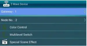
Color Control
Control the color with Hue (the palette on the top), Value (the first scroll bar), and Saturation (the second scroll bar).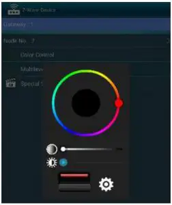
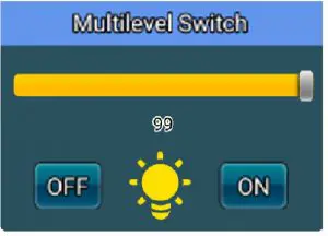
Multilevel Switch
Turn the switch ON/OFF (the button on the bottom), and adjust the brightness level (the scroll bar).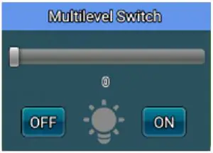
Special Scene Effect
Select the scene mode (the first drop-down menu), and the speed (the second drop-down menu).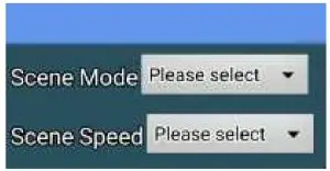
Scene Mode: Tick the box to select from Ocean, Lightning, Rainbow, Snow, and Sun.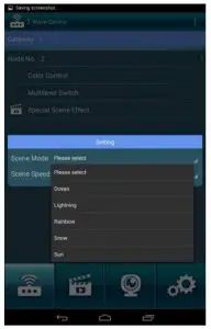
Speed: Tick the box to select Slow/ Medium/ Fast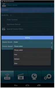
NOTE: Lightning Scene Mode does not support Speed adjustment
LED Indicator
| Status | LED Signal | Remark |
| Not Paired | Red& Green blinking by turns | |
| Paired up | Solid Green (Interval: 1sec.) |
External Controller
| Input type | Remark |
| Momentary | Momentary switch |
| Toggle | Toggle switch |
| Input operating mode | Remark |
| Normal | Each given switch key assigned to one output channel |
| Brightness | All channels are controlled together |
| Rainbow | Transition through all colours spectrum (Operates on RGB/RGBW channels only) |
Device Application
The RGBW Controller may control:
- 12 / 24VDC powered RGB strips
- 12 / 24VDC powered RGBW strips
- 12 / 24VDC powered LED strips, bulbs,
- 12 / 24VDC powered halogen lights
Additional features:
- controlled by momentary or toggle switches
Specification
| Item | Description |
| Power Supply | 12 / 24V DC |
| PWM output frequency | 488Hz |
| Electricity consumption | 12V: 0.48W; 24V: 0.72W |
| Radio signal power | 1mW |
| LED Indicator | Red/Green *1 |
| Button | Inclusion/Exclusion |
| Protocol | Z-Wave Plus |
| Operation Range | 100 feet (About 30M) |
| Housing | Plastic (PC8600) |
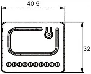
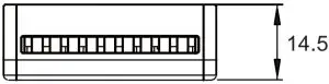
| Dimensions(L*W*H) | 40.5*32*14.5mm |
| Rated output power | 7A for single output channel, 13A at max. (3.25A for R.G.B.W. single output channel is suggested) |
| Max load (e.g. halogen bulbs) | At 12V- 192W combined At 24V- 384W combined |
| Application | Indoor use |
| Temperature | Storage: -20℃~70℃ Operation: 0℃~40℃ |
| Region Applied | Frequency | Data Rate |
| EU | 868.42 MHz | 9.6 kbps |
| EU | 868.4 MHz | 40 kbps |
| US | 908.42 MHz | 9.6 kbps |
| US | 908.4 MHz | 40 kbps |
| US | 916 MHz | 100 kbps |
| JP | 922.5 MHz | 100 kbps |
| JP | 923.9 MHz | 100 kbps |
| JP | 926.3 MHz | 100 kbps |
Specification is subject to change without prior notice.
Regulatory Compliance
CE Caution:
Electromagnetic compatibility and Radio spectrum Matters (ERM); Short Range Devices (SRD); Radio equipment to be used in the 25 MHz to 1,000 MHz frequency range with power levels ranging up to 500 mW; Part 2: Harmonized EN covering essential requirements under article 3.2 of the R&TTE Directive.
FCC Caution:
This device complies with Part 15 of the FCC rules standard. Operation is subject to the following two conditions:
- This device may not cause harmful interference, and.
- This device must accept any interference received, including interference that may cause undesired operation.
WEEE Information:
For EU (European Union) member users: According to the WEEE (Waste electrical and electronic equipment) Directive, do not dispose of this product as household waste or commercial waste. Waste electrical and electronic equipment should be appropriately collected and recycled as required by practices established for your country.
For information on recycling of this product, please contact your local authorities, your household waste disposal service or the shop where you purchased the product.
Z-Wave Plus:
This product can be included and operated in any Z-Wave network with other Z-Wave certified devices from other manufacturers and/or other applications. All non-battery operated nodes within the network will act as repeaters regardless of vendor to increase reliability of the network.


 Manual")


