Inditech 75×275 Parallel LOP DOT Touch
Contents hide
PRODUCT DESCRIPTION
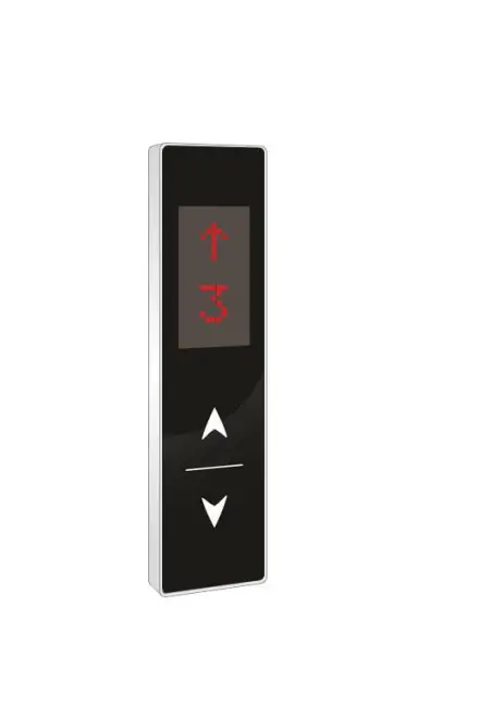
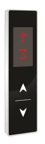
This product is Inditech’ s own design based upon high precision touch technology. It offers smooth operations to the user with best touch experience along with beautiful and attractive looks and aesthetics. It has Slim design with SS frame and stunning shiny acrylic fascia.
FEATURES/ SPECIFICATIONS
- Mount Type- Wall Mount
- Fascia- Black/White Color
- Input Supply- 12/24V
- Parallel Interface
- Support- Up to G+7 Floors
- Display Type- RED Dot Matrix (only single digit or character designing is possible)
- Buttons – Capacitive Touch
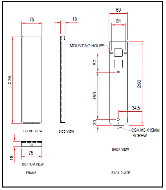
- Size (W*H*T)- 75x275x18MM
- Reliable
- Easy to use
- Durable
INSTALLATION STEPS
Note: Installation and Commissioning of the LOP is to be done by Authorized, Trained technician of Elevator Company.
Following are the steps to be taken for the installation of this panel.
- Remove the back plate of LOP
- Mount the back plate of LOP on the wall as per POINT NO. 5 Mounting Details.
- Do the connections as per POINT NO. 6 Connection Diagram below.
- Fix the LOP on back plate.
- Do the calibration as per POINT NO. 7 calibration process.
MOUNTING DETAILS
CONNECTION DETAILS
Note: For connection details refer below
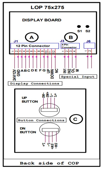
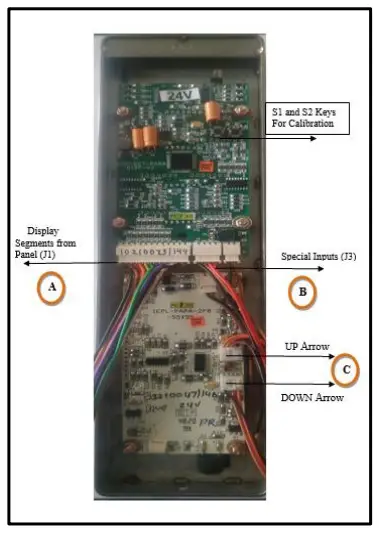
DISPLAY CONNECTION DETAILS
| Sr. No. | Wire Color | Connection Details (J1) (12 Pin Relimate Connector) |
| 1 | BLACK | 12V |
| 2 | BROWN | GND |
| 3 | RED | A |
| 4 | ORANGE | B |
| 5 | YELLOW | C |
| 6 | GREEN | D |
| 7 | BLUE | E |
| 8 | VIOLET | F |
| 9 | GRAY | G |
| 10 | WHITE | UP (ARROW) |
| 11 | BLACK | DOWN (ARROW) |
| 12 | BROWN | NC (No Connection) |
SPECIAL INPUT CONNECTION DETAILS
| Sr. No. | Wire Color | Connection Details (J3) (4 Pin Relimate Connector) |
| 1 | BLACK | IN1 (To Display digits 10 to 19) |
| 2 | BROWN | IN2 (To Display digits 20 to 23) |
| 3 | RED | OL (For Overload) |
| 4 | ORANGE | M (For Maintenance) |
| Sr. No. | Wire Color | Connection Details Touch Button (4 Pin Relimate Connector) |
| 1 | BLACK | L+ |
| 2 | BROWN | 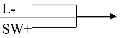 UP/DN UP/DN |
| 3 | RED | SW+ |
| 4 | ORANGE | SW- |
CALIBRATION PROCESS
CALIBRATION SET PROCESS
- Give segment which is set to for floor.
- Press S1 and S2 both keys then display shows ‘- – ‘then release both the keys.
- When’- -‘ symbol stop blinking, press S1 and S2 for increment & decrement.
- After pressing S1 & S2 keys for increment and decrement it shows digits Which we have to set.
- After showing display which is we have to set, then release the key after sometime.
- Display will blink and shows – – means calibration is saved & it will display Saved floor.
- Repeat same procedure for next floor calibration.
CALIBRATION RESET PROCESS
- If we want to display only normal 7 segment, then no need to calibrate.
- Short the pin No. 1 & 2 of J4 berg strip for 10 second.
- After completion of 10 second display is shows ‘FR’ it means process is Completed and program is in normal 7 segment mode.
- Give 7 segments to the connector J1, display will show floor.