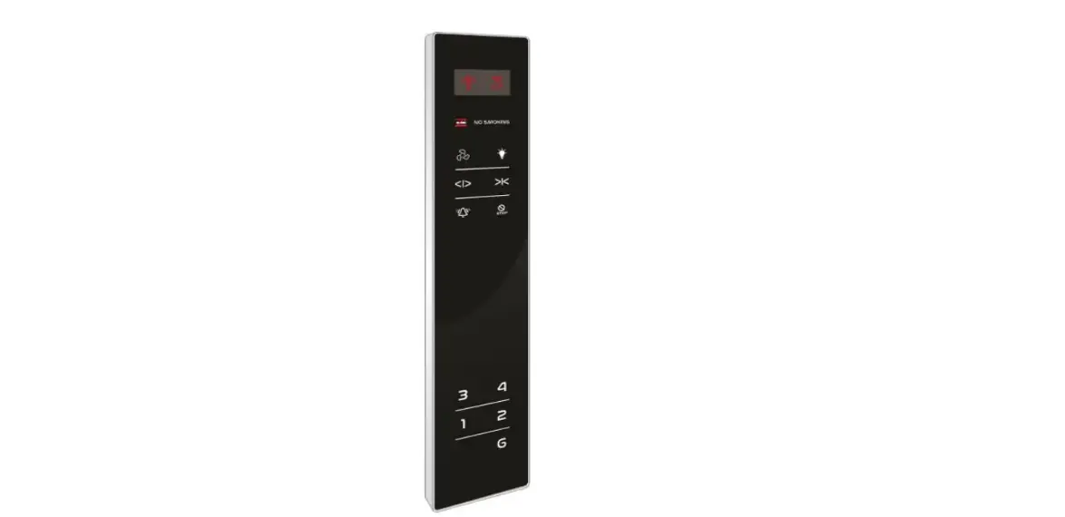
INDITECH PARALLEL COP 170×900 DOT TOUCH BLACK FACIA 12V G+4

PARALLEL COP 170×900 DOT TOUCH BLACK FACIA 12V G+4
CONNECTION DETAILS:
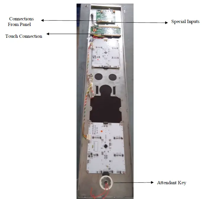
Note: For connection details refer below page.
DISPLAY AND SWITCH CONNECTION DETAILS:
| Sr. No. | Wire Color | Connection Details (J1) (12 Pin Relimate Connector) |
| 1 | BLACK | 24V |
| 2 | BROWN | GND |
| 3 | RED | A |
| 4 | ORANGE | B |
| 5 | YELLOW | C |
| 6 | GREEN | D |
| 7 | BLUE | E |
| 8 | VIOLET | F |
| 9 | GRAY | G |
| 10 | WHITE | UP (ARROW) |
| 11 | BLACK | DOWN (ARROW) |
| 12 | BROWN | NC (No Connection) |
| Sr. No. | Wire Color | Connection Details (J3) (4 Pin Relimate Connector) |
| 1 | BLACK | IN1 (To Display digits 10 to 19) |
| 2 | BROWN | IN2 (To Display digits 20 to 23) |
| 3 | RED | OL (For Overload) |
| 4 | ORANGE | M (For Maintenance) |
| Sr. No. | Wire Color | Connection Details Touch Button (4 Pin Relimate Connector) |
| 1 | BLACK | L+ 12V |
| 2 | BROWN | L- G, 1, 2, 3, 4 SW+ |
| 3 | RED | |
| 4 | ORANGE | SW- GND |
Connection Details: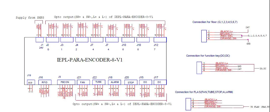 Mounting Details:
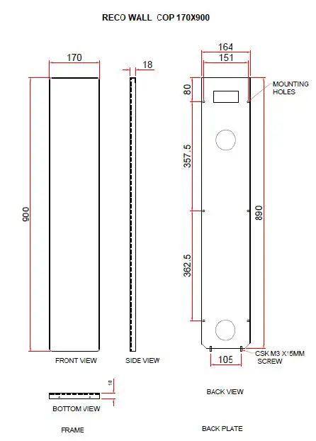
Features:
- We can provide logo as per customer demand.
- Available for G+4 floors.
- Facia- Black color
- Display Type- Dot Matrix
- Buttons – TOUCH
- Reliable
- Easy to use
- Durable
- Reliable
Specifications
- Input Supply- 24V
- COP size-170×900
- Thickness-18MM
- Mount Type- Wall mount
Calibration process:
- Give segment which is set to for floor.
- Press S1 and S2 both keys then display shows ‘- – ‘then release both the keys.
- When’- -‘ symbol stop blinking, press S1 and S2 for increment & decrement.
- After pressing S1 & S2 keys for increment and decrement it shows digits Which we have to set.
- After showing display which is we have to set, then release the key after sometime.
- Display will blink and shows – – means calibration is saved & it will display Saved floor.
- Repeat same procedure for next floor calibration.
Calibration reset process:
- If we want to display only normal 7 segment then no need to calibrate.
- Short the pin No. 1 & 2 of J4 berg strip for 10 second.
- After completion of 10 second display is shows FR it means process is Completed and program is in normal 7 segment mode.
- Give 7 segments to the connector J1, display will show floor.


