ALPHA DATA ADC-XMC-STANDALONE Board
Introduction
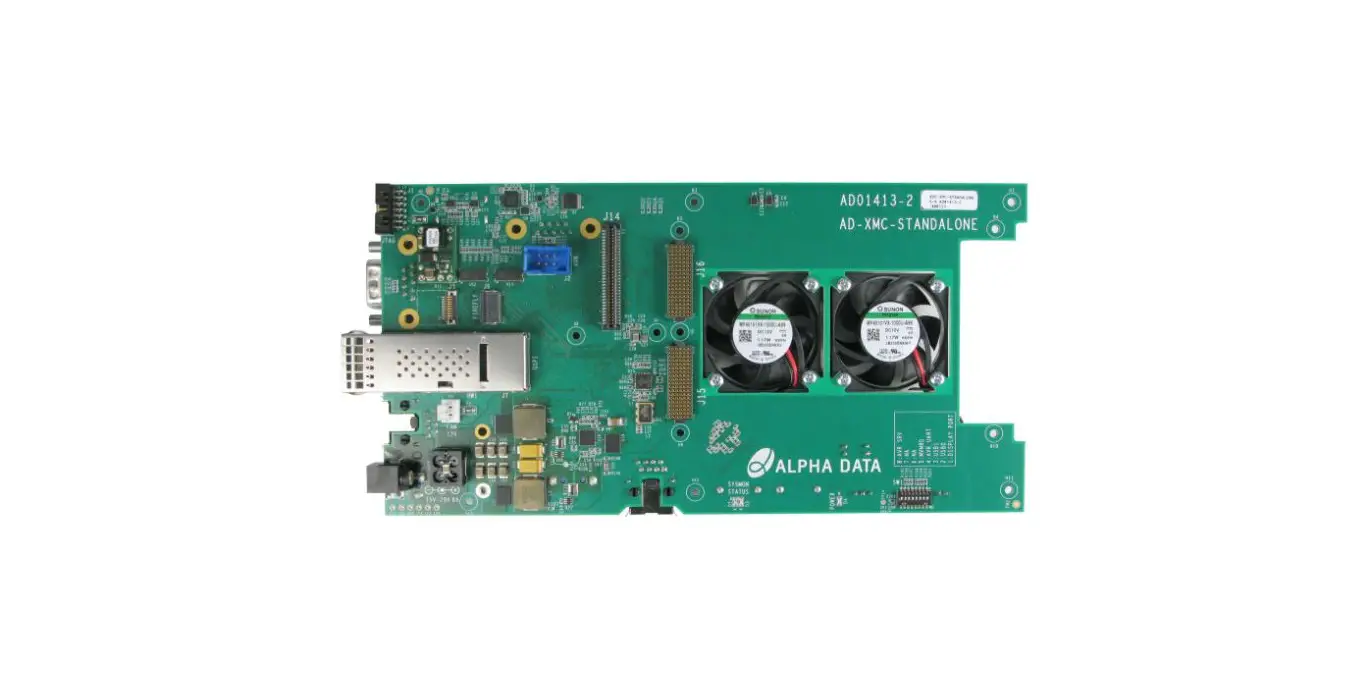
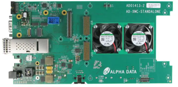
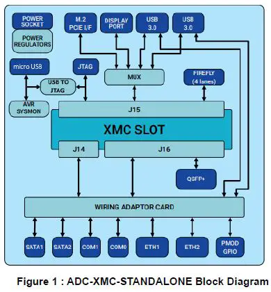
The ADC-XMC-STANDALONE is a standalone carrier for Alpha-Data XMCs. The board provides Ethernet, Serial COM, USB, SATA, M.2 PCIe, QSFP, FireFly, GPIO and DisplayPort IO options. To allow compatibility with various XMC board pinouts, a personality wiring card that matches the XMC pinout is used to route signals through to the IO interfaces.
Apart from the IO functionality, ADC-XMC-STANDALONE uses a single 15V-30V input power supply, and generates all supplies required by the XMC site internally. An on-board system monitor micro-controller provides voltage/current monitoring of the generated power supplies, as well as providing the capability to turn the supplies on/off via the micro USB interface. A USB to JTAG circuit is also provided, giving access to the JTAGchain without requiring an external JTAG box.IO interface support is dependent on the XMC type fitted, as well as the configuration of that XMC board.
Board Features
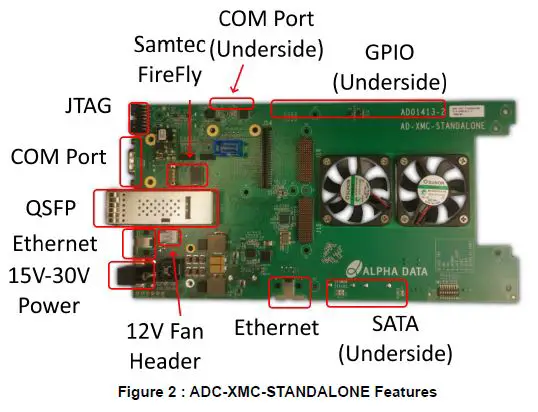
The following photos highlight the various features of the ADC-XMC-STANDALONE
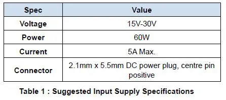
Main Input Power Supply Requirements
The total power requirement for the main input supply will vary depending on the XMC board fitted, as well as the particular FPGA design within that board. A 60W supply would likely be more than enough for most FPGA designs before thermal limits of the device and heatsink become the limiting factor. Alpha-Data can provide a power supply estimator spreadsheet to estimate the total power requirements for a particular FPGA design with a particular XMC board.
Installation and Power Up
The required personality card should be attached to connectors J21, J22 and J23 on the read of the board prior to attaching the XMC card to J14, J15 and J16.
To power up the board, ensure that power switch SW2 is OFF, and connect a 15V-30V power supply. To turn the board ON, switch the power switch S2 to ON.
JTAG Interface
A USB to JTAG circuit is provided, giving access to the XMC JTAG interface without the need for an external programming box (e.g. Xilinx Platform Cable II). The USB to JTAG converter is compatible with Vivado, and will appear in hardware manager as a Digilent device. A 14-pin JTAG header is also available, with an onboard multiplexer to switch between the 14-pin header or the USB to JTAG converter. The multiplexer selects the USB to JTAG circuit when a micro USB cable is attached.
Current/Voltage Monitoring
The ADC-XMC-STANDALONE provides high-side current sense functionality on both the 12V and 3V3+3V3_AUX supplies. These values can be reported over the micro USB interface, using the alpha-data “avr2util” utility.
Avr2util for Windows and the associated USB driver can be downloaded here:
https://support.alpha-data.com/pub/firmware/utilities/windows/
Avr2util for Linux can be downloaded here:
https://support.alpha-data.com/pub/firmware/utilities/linux/ Use “avr2util.exe /?” to see all options.
For example “avr2util.exe /usbcom com4 display-sensors” will display all sensor values. Note that ‘com4’ is used here as an example, and should be changed to match the com port number assigned under windows device manager
On-Board Generated Power Supplies
The ADC-XMC-STANDALONE generates the 3V3/3V3_AUX/12V0/-12V0 supplies required by the XMC site from a single 15V-30V input supply. Each supply has the following specifications:
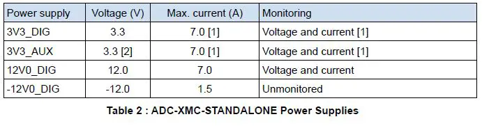
- The 3V3_DIG and 3V3_AUX rails are generated from the same supply, so the maximum current is the combination of 3V3_AUX + 3V3_DIG. The current monitoring also measures the combined current.
- The 3V3_AUX rail is an always-on 3.3V auxiliary power supply from the 15V-30V input.
Connector Pin Assignments when used with an XMC card
The pinout depends on the personality board used. Select the correct table below for the pinout. Any pins not listed in the tables below are NC
ADM-XRC-9R1 pcb revision 3+ pinout
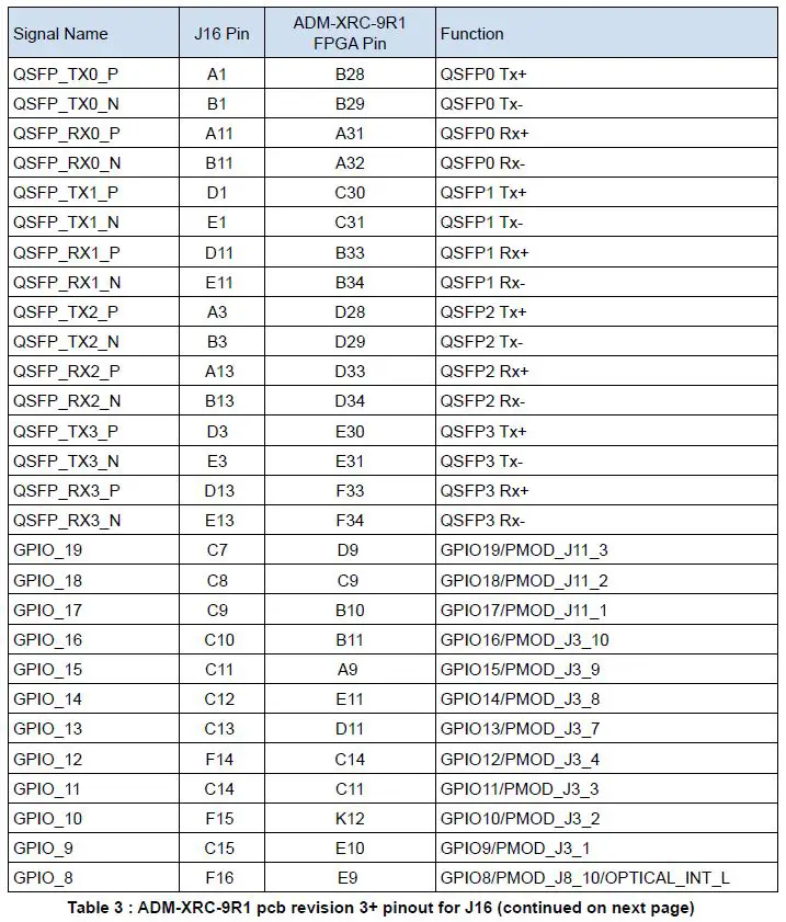
| Signal Name | J16 Pin | ADM-XRC-9R1 FPGA Pin | Function |
| GPIO_7 | C16 | H10 | GPIO7/PMOD_J8_9/OPTICAL_RESET_L |
| GPIO_6 | F17 | C10 | GPIO6/PMOD_J8_8/FIREFLY_MODPRS_L |
| GPIO_5 | C17 | H9 | GPIO5/PMOD_J8_7/FIREFLY_SCL |
| GPIO_4 | F18 | A10 | GPIO4/PMOD_J8_4/FIREFLY_SDA |
| GPIO_3 | C18 | K10 | GPIO3/PMOD_J8_3/QSFP_MODPRS_L |
| GPIO_2 | F19 | C13 | GPIO2/PMOD_J8_2/QSFP_SDA |
| GPIO_1 | C19 | B13 | GPIO1/PMOD_J8_1/QSFP_SCL |
Table 3 : ADM-XRC-9R1 pcb revision 3+ pinout for J16
| Signal Name | J14 Pin | Function |
| Front RJ1 pin1 | 1 | Ethernet0 MD0+ |
| Front RJ1 pin2 | 3 | Ethernet0 MD0- |
| Front RJ1 pin3 | 7 | Ethernet0 MD1+ |
| Front RJ1 pin4 | 2 | Ethernet0 MD1- |
| Front RJ1 pin5 | 4 | Ethernet0 MD2+ |
| Front RJ1 pin6 | 9 | Ethernet0 MD2- |
| Front RJ1 pin7 | 8 | Ethernet0 MD3+ |
| Front RJ1 pin8 | 10 | Ethernet0 MD3- |
| Side RJ1 pin1 | 13 | Ethernet1 MD0+ |
| Side RJ1 pin2 | 15 | Ethernet1 MD0- |
| Side RJ1 pin3 | 19 | Ethernet1 MD1+ |
| Side RJ1 pin4 | 14 | Ethernet1 MD1- |
| Side RJ1 pin5 | 16 | Ethernet1 MD2+ |
| Side RJ1 pin6 | 21 | Ethernet1 MD2- |
| Side RJ1 pin7 | 20 | Ethernet1 MD3+ |
| Side RJ1 pin8 | 22 | Ethernet1 MD3- |
| Front RJ2 pin3 | 43 | COM1 Tx |
| Front RJ2 pin6 | 42 | COM1 Rx |
| Side RJ2 pin3 | 47 | COM2 Tx |
| Side RJ2 pin6 | 48 | COM2 Rx |
| Front USB DP | 27 | USB Data+ |
| Front USB DM | 25 | USB Data- |
| Front USB VBus | 29 | USB Vcc |
| Side USB DP | 28 | USB Data+ |
| Side USB DM | 26 | USB Data- |
| Side USB VBus | 30 | USB Vcc |
Dimensions
| Dimension | Measurement |
| X PCB | 219mm |
| X including connectors | 230.15mm |
| Y PCB | 112.5mm |
| Y including connectors | 113.1mm |
Table 5 : ADC-XMC-STANDALONE PCB dimensions
Order Code
ADC-XMC-STANDALONE/X/T
| Name | Symbol | Configurations |
| XMC Personality Card | x | 9R1 = ADM-XRC-9R1, 7Z1 = ADM-XRC-7Z1, 7Z2 = ADM-XRC-7Z2, 7Z4 = ADM-XRC-7Z4 |
| XMC Connector Type | t | blank = XMC (VITA 42) Connectors, /X2 = XMC2 (VITA 61) Connectors |
Table 6 : ADC-XMC-STANDALONE Order Code
Revision History
| Date | Revision | Nature of Change |
| 22 Feb 2021 | 1.0 | Preliminary issue |
| 18 May 2021 | 1.1 | Added board diagram, added PMOD connector pin numbers, added 9R1 FPGA pin numbers |
| 14 Oct 2021 | 1.2 | Added description of the USB to JTAG, moved pin assignments to the end of the document |
© 2021 Copyright Alpha Data Parallel Systems Ltd.
All rights reserved.
This publication is protected by Copyright Law, with all rights reserved. No part of this publication may be reproduced, in any shape or form, without prior written consent from Alpha Data Parallel Systems Ltd.
Head Office
Address: Suite L4A, 160 Dundee Street,
Edinburgh, EH11 1DQ, UK
Telephone: +44 131 558 2600
Fax: +44 131 558 2700
email: [email protected]
website: http://www.alpha-data.com
US Office
611 Corporate Circle, Suite H
Golden, CO 80401
(303) 954 8768
(866) 820 9956 – toll free
[email protected]
http://www.alpha-data.com
All trademarks are the property of their respective owners. Page Intentionally left blank


