![]()
TuffSeal®
Heavy Capacity Junction Box JB8SP/JB8SPT
Installation Manual
Introduction
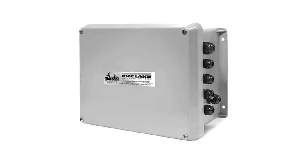
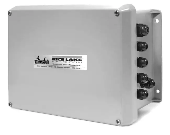
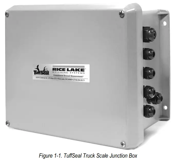
The TuffSeal® eight-channel signal trim junction box is used in truck scale installations and can accommodate up to eight load cells. Additional load cells can be connected to the junction box by wiring additional junction boxes to the expansion terminal located on the mainboard. Both the JB8SP and JB8SPT models can withstand 900 PSI water pressure when correctly installed. Both models have a new Prevent® breather vent. The breather vent inhibits the buildup of pressure caused by sudden temperature or environmental changes. The breather vent should be changed every six months to one year as it will become dirty over time.
Both models will function properly without modification; however, load cell output can be individually trimmed with potentiometers. For more information, see Section 5.0 on page 8.
Transient protection comes standard with the JB8SPT model junction box.
 Manuals and additional resources are available from the Rice Lake Weighing Systems website at www.ricelake.com
Warranty information can be found on the website at www.ricelake.com/warranties
Model Designations
The TuffSeal eight-channel junction box comes in two different models. They include:
| Part No. | Name | Description |
| 91782 | JB8SP | Truck Scale Signal Trim Version |
| 91783 | JB8SPT | Truck Scale Signal Trim Version with Transient Protection |
| 173807 | JB8SP-FM-8 | JB8SP signal trim eight-channel with expansion, FM approved |
Table 1-1. Model Designations
Safety
Safety Signal Definitions:
 | Indicates an imminently hazardous situation that, if not avoided, will result in death or serious injury. Includes hazards that are exposed when guards are removed. |
| Indicates a potentially hazardous situation that, if not avoided, could result in serious injury or death. Includes hazards that are exposed when guards are removed. | |
| Indicates a potentially hazardous situation that, if not avoided, could result in minor or moderate injury. | |
| Indicates information about procedures that, if not observed, could result in damage to equipment or corruption to and loss of data. |
General Safety
Do not operate or work on this equipment unless this manual has been read and all instructions are understood.
Failure to follow the instructions or heed the warnings could result in injury or death. Contact any Rice Lake Weighing Systems dealer for replacement manuals.
![]() Failure to heed could result in serious injury or death.
Failure to heed could result in serious injury or death.
Do not install where water may accumulate; this could cause electric shock and damage to the unit.
Do not use if wiring is frayed or worn.
Do not use if the cover is off or the unit has not been sealed properly.
Do not place fingers into slots or possible pinch points.
Do not use this product if any of the components are cracked.
Do not make alterations or modifications to the unit.
Do not remove or obscure warning labels.
Ensure load cells are correctly wired; incorrect wiring could cause damage to the unit.
Installation
The junction box should be mounted in a location convenient for servicing and away from standing water. Mount the enclosure in a location so that the load cell cable need not be cut, nor length added. Load cell output is temperature compensated for the supplied cable length; altering the length can change the cell’s signal output.
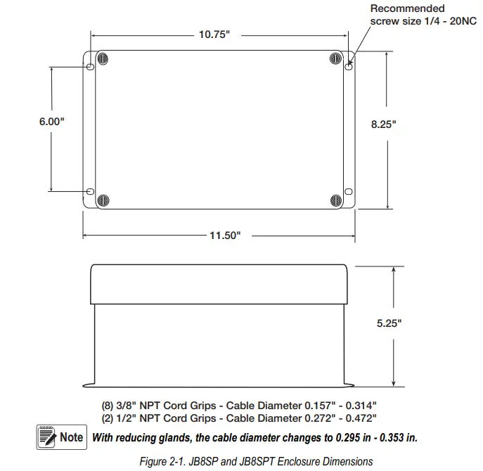
Depending on the mounting surface, the enclosure is attached using four pan-head screws, bolts or other suitable fasteners (not included). Figure 2-1 shows the dimensions for mounting the enclosure.
Wiring the Junction Box
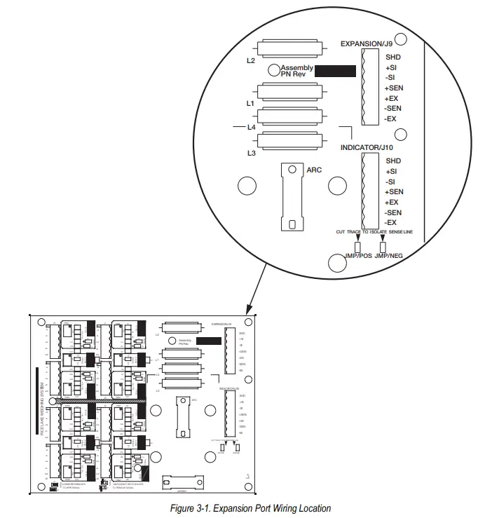
All TuffSeal junction box models have been designed to connect and trim up to eight load cells per board. However, it is possible to use this box with two, four, six, and eight load cell combinations. Use the expansion port on the mainboard (Figure 3-1), to connect multiple junction boxes in series to accommodate applications that have ten or more load cells.
- After determining the wiring pattern, route the load cell cables through the cord grip assemblies and leave the grip loose until final closure.
- Before connecting the load cell wires to the terminals, strip the wire insulation back 1/4″ to expose the wire. The pluggable connector will accommodate 12 to 28 gauge wire.
- To connect the load cell wires to the appropriate connectors, open each pole with a small screwdriver and insert the appropriate wire into the exposed wire opening.
- Tighten the end screw with the screwdriver to secure each wire into place.
- Plug the terminal to the appropriate header socket.
- The indicator terminal is used to connect the main cable to the weight indicator. Determine the indicator’s load cell input connections from the operation manual.
- Run a cable from the indicator terminal into the junction box through the larger cord grip.
- Make the connections on the indicator terminal using the same procedure as inserting load cell cables to the appropriate connectors.
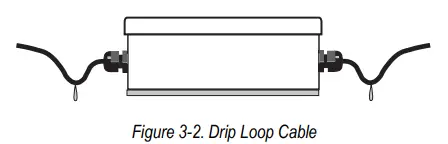
![]() If cables could be exposed to water or other liquids, bend a short downward loop in all cables near the cord grips so any fluids draining down the cables will drop off before reaching the junction box. See Figures 3-2.
If cables could be exposed to water or other liquids, bend a short downward loop in all cables near the cord grips so any fluids draining down the cables will drop off before reaching the junction box. See Figures 3-2.
Transient Board Installation Procedure
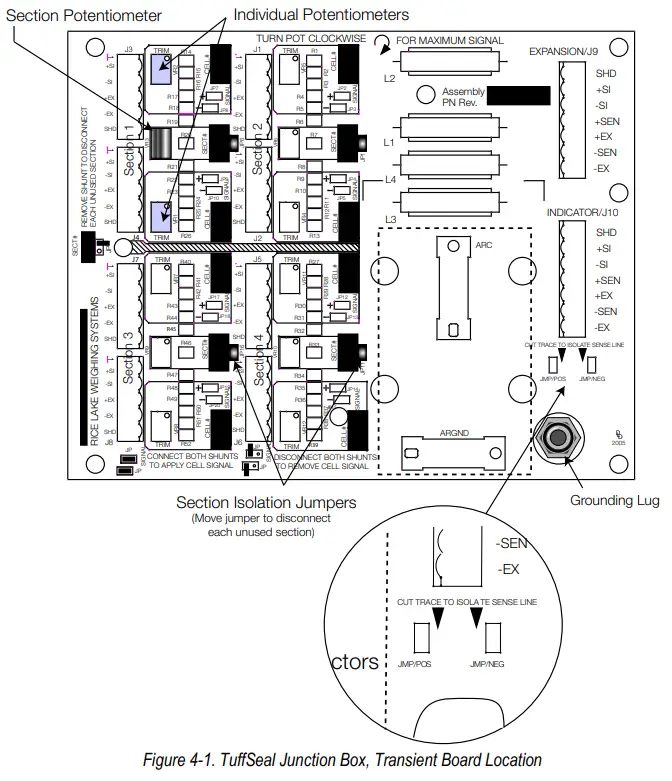
The JB8SPT comes standard with transient protection (PN 89894). Figure 4-1 shows where the transient protection board plugs into the main CPU board.
Grounding Transient Protection
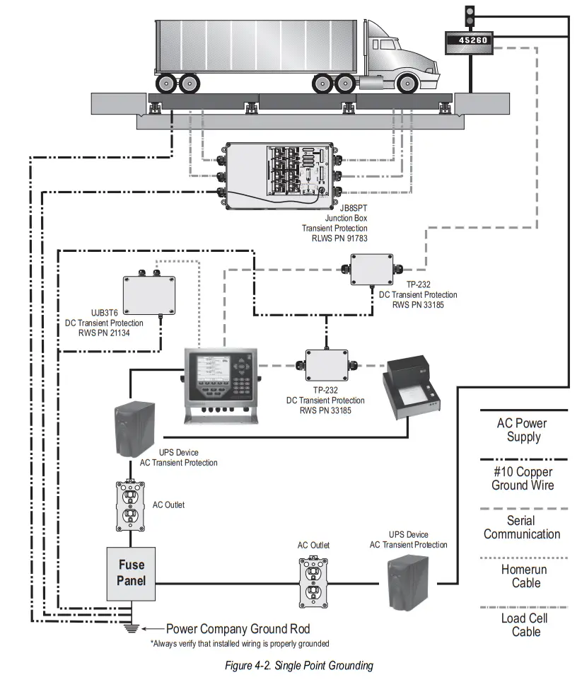
To ensure proper operation, the JB8SP and JB8SPT must be grounded to protect the junction box from stray voltage and is essential for the operation of the DC transient protection incorporated into the junction box.
A ground wire has already been attached to the grounding lug located on the mainboard and extends out of the junction box cord grip. Securely attach a 10 gauge ground wire to the ground wire that’s already coming out of the junction box. The final ground wire connection must be at the AC power supply ground terminal, separate from the truck scale ground.
Figure 4-2 illustrates an example of single-point grounding of the junction box and the truck scale.
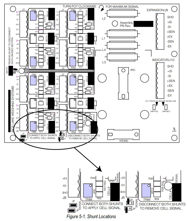
Trimming Procedure
Trimming is a process of equalizing the output from multiple individual load cells. If needed, load cell output can be individually trimmed with potentiometers.
Whenever a substantial amount of trim (more than 7% of normal output), seems necessary to equalize output, check for other possible problems. The best trim is always the least amount of trim.
The JB8SP and JB8SPT is a signal trimming devices with individual and section trimming potentiometers (Figure 4-1 on page 6).
Use the following steps to properly trim the JB8SP and JB8SPT junction box.
![]() If using two junction boxes with an expansion cable between them, make sure to cut the sense trace on the board that has the homerun cable connected to it (see figure 4-1 on page 5). This ensures sensing out to the furthest junction box within the system. A sic conductor cable must be used between the two junction boxes to ensure
If using two junction boxes with an expansion cable between them, make sure to cut the sense trace on the board that has the homerun cable connected to it (see figure 4-1 on page 5). This ensures sensing out to the furthest junction box within the system. A sic conductor cable must be used between the two junction boxes to ensure
proper functioning of sense.
- Determine the number of load cells needed. When section trimming, it is acceptable to use combinations of load cells other than eight, but the combination must be an even number of cells.
- Turn all the individual cell and section potentiometers clockwise to give maximum signal output from each section.
Make sure to remove all shunt jumpers of the individual cells that are not being used to disable them and ensure the section potentiometer is turned fully. If desired, all the potentiometers can be adjusted 3-5 turns counter-clockwise to allow trim capabilities both positive and negative.
 - Trim by turning potentiometers counter-clockwise to lower output to match the lowest value.
- Remove all weight from the scale and zero the indicator. Place calibrated test weights over each load cell or section.
The number of test weights to be used will depend on the scale configuration; for specific recommendations, refer to Handbook 44, published by the National Institute of Standards and Technology (NIST). - Record the value displayed on the indicator after the test weight is placed in turn over each load cell, or over each section. Select the load cell or section that has the lowest value as the reference point. This cell or section will not be trimmed.
- Place the same test load over each cell or section in turn. Using the corresponding potentiometer, trim each cell or section down to equal the reference point. As load cell corrections are interactive, check zero after every adjustment to avoid zero shift.
- Check cells or sections again and repeat steps six, seven, and eight as needed.

- Pull the excess cable out of the enclosure.
- Using a wrench, tighten the nut until the rubber touches the cable completely.
- Tighten the nut an additional 1/2 turn (180º). To be watertight, each cord grip must be tightened so the rubber sleeve begins to protrude from the hub.
- Unused hubs must be properly plugged to prevent moisture entry. Extra hole plugs are provided to seal up any unused hubs.
- Remove the desiccant from the plastic bag, and insert the desiccant bag into the junction box before closing. Inspect the desiccant during normal service and change the desiccant as needed.
- Replace the cover and torque the cover screws in an alternating pattern to 15 in-lb to be certain the gasket is compressed equally in all locations.
![]()
Rice Lake continually offers web-based video training on a growing selection of product-related topics at no cost. Visit www.ricelake.com/webinars
© Rice Lake Weighing Systems Specifications are subject to change without notice.
Rice Lake Weighing Systems is an ISO 9001 registered company.
230 W. Coleman St. • Rice Lake, WI 54868 • USA
U.S. 800-472-6703 • Canada/Mexico 800-321-6703 • International 715-234-9171 • Europe +31 (0)26 472 1319
www.ricelake.com
April 27, 2021
PN 89927 Rev D
An ISO 9001 registered company
© Rice Lake Weighing Systems. All rights reserved.
Rice Lake Weighing Systems® is a registered trademark of Rice Lake Weighing Systems.
All other brand or product names within this publication are trademarks or registered trademarks of their respective companies.
All information contained within this publication is, to the best of our knowledge, complete and accurate at the time of publication. Rice Lake Weighing Systems reserves the right to make changes to the technology, features, specifications and design of the equipment without notice.
The most current version of this publication, software, firmware and all other product updates can be found on our website:
www.ricelake.com


