![]()
Installation Guide
SIGN108
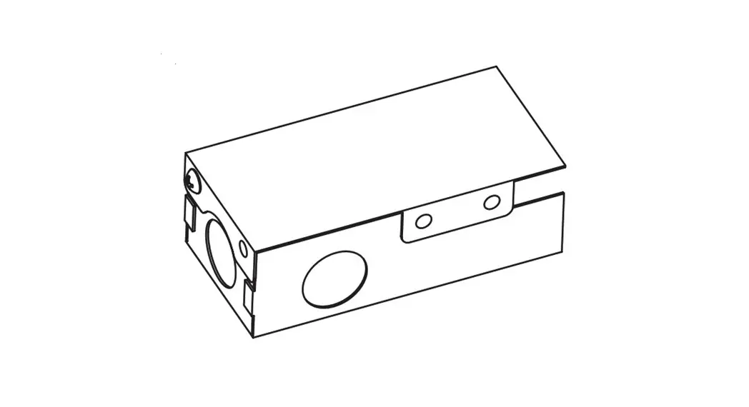
Power Supply Junction Box
GEPSJB60
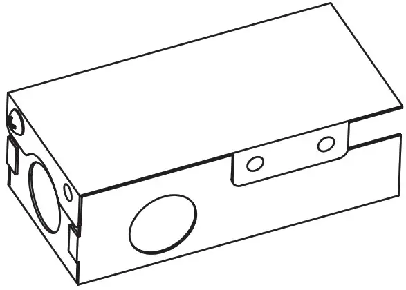
Junction Box Features
- GEPSJB60 supports: GEPS12-60, GEPS12D-60U, GEPS24-80, GEPS24D-80U,
- GEPS12-60U-NA, GEPS12SE-60U-NA, GEPS12-60U-GL, GEPS24-100U-NA,
- GEPS24-100U-GL, GEPS24-100U-GLX
- Can be used on primary side of the power supplies listed above; or any other power supply that similarly fits, with a class 2 output where otherwise acceptable in the application.
- Suitable for dry or damp locations
![]() BEFORE YOU BEGIN
BEFORE YOU BEGIN
Read these instructions completely and carefully.
WARNING
RISK OF ELECTRIC SHOCK:
- Disconnect power at fuse box or circuit breaker before servicing or installing product.
- Properly ground Tetra ® power supply.
RISK OF FIRE:
- Use only approved wire for input/output connection. Minimum size 18 AWG (0.82 mm2).
- Use only approved wire for input connection. Maximum size 14 AWG; minimum 75C rated.
- Branch circuit limit of 15A.
- Follow all local codes.
Installation
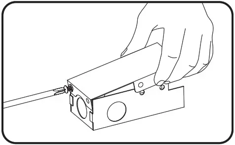
1. Remove screw and lock washer and snap the top cover off of the junction box.
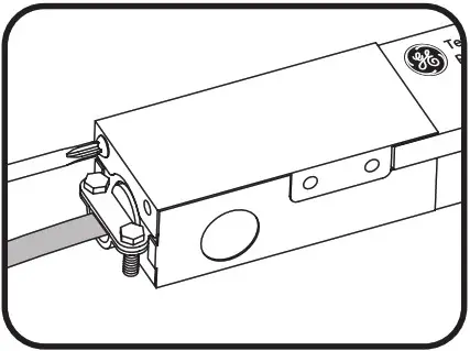
2. Select a wire entry knock out location and carefully remove metal plug. Install wire box fitting and supply wire and secure in place.
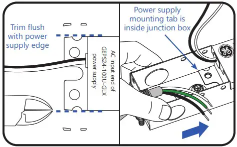
3A. For GEPS24-100U-GLX only: On the AC input end of power supply, trim or grind sides of mounting tab flush with power supply. Then slide junction box onto AC input end of power supply and align mounting holes. Ensure power supply mounting tab is inside the junction box.
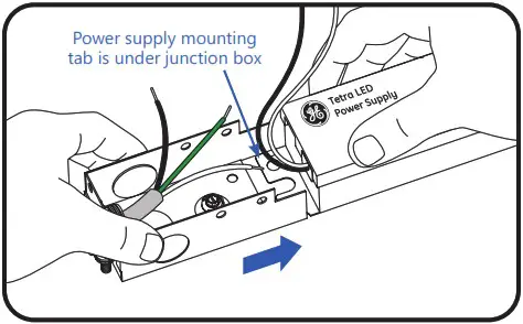
3A. For all other power supplies: Slide junction box onto AC input end of power supply and align mounting holes. Ensure power supply mounting tab is under the junction box.
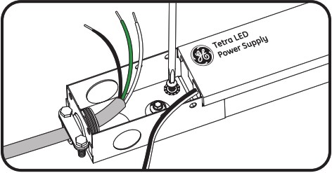
4. Mount and secure Junction Box and Tetra Power Supply using #6 or #8 screws and star-type lock washers in both holes.
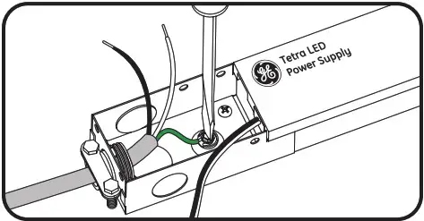
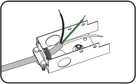
5. Connect AC line ground wire to Junction Box ground screw.
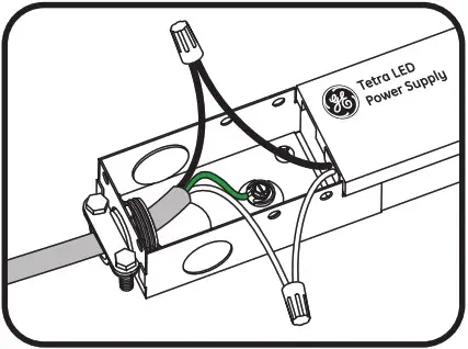
6. Connect Tetra Power Supply to AC line per instructions enclosed with the power supply.
7. Neatly fold wires within the Junction Box and reattach cover with mounting screw and washer.
Tighten securely.
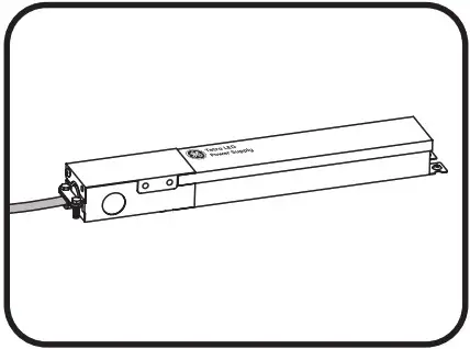
8. Complete installation. Continue with LED light engine connections.
Conforms to the following standards:
![]()
![]()
© 2022 Current Lighting Solutions, LLC. All rights reserved. Information and specifications subject to change without notice. All values are design or typical values when measured under laboratory conditions.
(Rev 03/06/23)
SIGN108


