Milleteknik ME010000024BB01 BATTERY BOX 24V M Instruction Manual
ABOUT
ECO is a series of small and reliable battery backups.
Name, article number and e-number (SV)
| Name | Article number | E-number (SV) |
| ECO 24V 3A S | SM01C10224P030 | 5213516 |
| ECO 12V 10A M | ME01C10212P100 | 5213519 |
| ECO 24V 5A M | ME01C10224P050 | 5213521 |
| ECO 24V 10A M | ME01C10224P100 | 5213522 |
| ECO 12V 5A S | SM01C10212P050 | 5213650 |
Notice
This unit should be installed on a wall or in a 19″ rack, indoors. The temperature must be 15 – 30 ° C.
Mains voltage must be disconnected during installation. Only authorized persons should install and maintain the unit.
Commissioning
This unit should be installed on a wall, indoors andthetemperature should
be 15 – 30 ° C. IP class 20. Mains voltage must be disconnected during installation. Only authorized persons should install and maintain. The system works normally when the D6 is lit with a solid green light. Follow the steps below to commission.
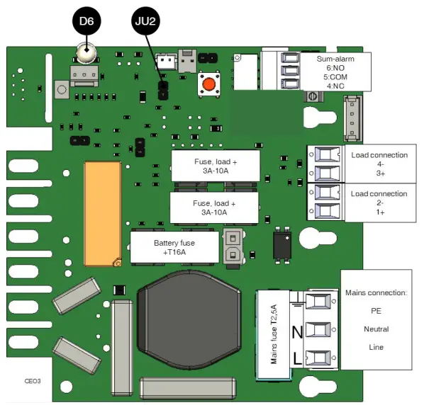
Connect in this order
- Load on load output, (see picture).
- Batteries, (see Battery).
- Sum alarm, optional, (see picture).
Mounting
100 mm free space must be left around the unit. Use four screws suitable for the wall to mount the cabinet.
Start-up
- Switch on incoming mains
- D6 is green, normal
- Switch off the mains voltage to check that the unit is operating in battery mode, the LED lights green when the unit is running on
- Switch on incoming mains
- LED, D6, is green, normal
Batteries
Slide the battery in from the side with the battery terminals facing the short side. Connect red cable to + (plus) and black cable to – (minus).
Alarm s
D6 illuminates orange in the event of an alarm: Low battery voltage / delayed power failure. Alarm relay (via terminal sum alarm) gives alarm for: Low bat- tery voltage / delayed mains interruption.
Control alarm limit Alarm for low battery voltage in battery operation can be controlled.
By jumpering JU2, the limit for when the unit should give an alarm can be lowered.
Alarms are given when the battery voltage in battery drops below the limit. Alarm limits
Battery replacement
- If possible, disconnect the mains voltage when replacing the
- Disconnect the battery fuse on the circuit
- Disconnect battery Note how battery cables are mounted before removing them.
- Insert and fasten the new
- Connect the battery cables in the same way as Replace the bat- tery fuse on the circuit board.
- Switch on mains The indicator LED may light up orange for a couple of hours, until the batteries are charged.
- Test the system by briefly disconnecting the mains voltage, (= the load is driven by the batteries), and then switch on the mains voltage
Technical data
| Number of secured outputs | 2 pcs |
| Fuse on outputs | + is fused |
| ECO 12V 5A S | T5A |
| ECO 24V 3A S | T3A |
| ECO 12V 10A M
ECO 12V 10A FLX S | T10A |
| ECO 24V 5A M
ECO 24V 5A FLX S | T5A |
| ECO 24V 10A M
ECO 24V 10A FLX S | T10A |
| Alarm via: | Indicator LED and alternating relay |
| Indicator diode, D6. Green: | Ok |
| Red: | Undervoltage, (LED is green in the event of a power failure until the battery voltage drops below the alarm limit, at which point the LED switches to red). |
| Deep discharge protection | When voltage drops below 20.2 V |
| Protection against: | Overload, overvoltage, overtemperature, short circuit and deep discharge. |
![]()
| Other information | |
| Support: | 031- 34 00 230, [email protected], www.milleteknik.se |

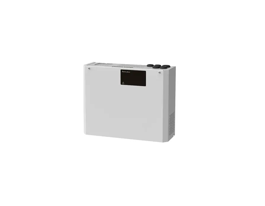
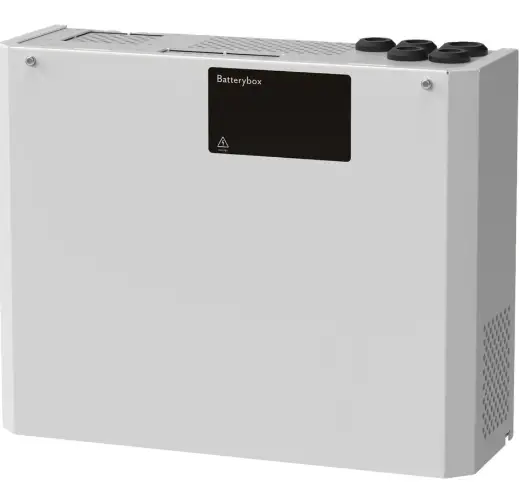
BATTERY BOX 24V M
About
Battery Box 24V M is a battery box to extend the operating time of ECO 24V 5A M or ECO 24V 10A M.
COMMISSIONING
This unit should be installed on a wall, indoors and the temperature should be 15 – 30 ° C. IP class 20. Mains voltage must be disconnected during installa- tion. Only authorized persons should install and take care of the maintenance.
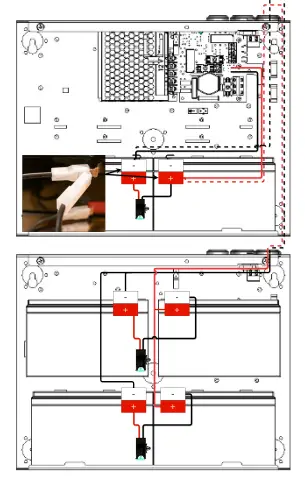
CONNECTION OF BATTERIES IN BATTERY BOX
- Slide the battery in from the side with the battery terminals facing the short Connect red cable to + (plus) and black cable to – (minus).
- Disconnect battery fuse on battery backup or disconnect mains
- Insert batteries starting from the bottom. Only use new batteries during installation and battery replacement.
- Connect fuses on Link to installation video, (swedish text).
- Connect cables from battery box to battery Cables are routed on the back and in through cable entries on the top of the battery backup.
- Connect one of the terminals (on battery in battery backup) with the double connector, see
- Replace the battery fuse in the battery backup or switch on the mai
COMMISSIONING OF BATTERY BACKUP WITH BATTERY BOX
After connecting the wiring, follow the instructions for commissioning battery backup.
TECHNICAL DATA
| Battery Box 24V M | |
| Number of batteries | 4 pieces. |
| Battery type | 14 Ah 12 V batteries. |


