Intermec PX4i, PX6i Print Kit
Before You Begin
This section provides you with technical support information and sources for additional product information.
Global Services and Support
Warranty Information
Before You Begin
AWOO Systems
102-1304 SK Ventium
522 Dangjung-dong
Gunpo-si, Gyeonggi-do Korea, South 435-776 Contact: Mr. Sinbum Kang
Telephone: +82-31-436-1191
E-mail: [email protected]
IN Information System PTD LTD
6th Floor
Daegu Venture Center Bldg 95
Shinchun 3 Dong
Donggu, Daegu City, Korea
E-mail: [email protected] or [email protected]
Who Should Read This Manual
This document provides you with information about the features of components in the PX4i and PX6i Print Kits, and is intended for the person responsible for evaluating Print Kit components for use in a custom print applicator system.
Related Documents
Here are some related Intermec documents you might find useful:
- PX4i and PX6i High Performance Printer User’s Manual
- Intermec Fingerprint Command Reference Manual
- Intermec Fingerprint Developer’s Guide
The Intermec web site at www.intermec.com contains our documents (as .pdf files) that you can download for free.
To download documents
- Visit the Intermec web site at www.intermec.com.
- Click the Products tab.
- Using the Products menu, navigate to your product page. For example, to find the PX4i printer product page, click Printers and Media > Fixed Printers > PX4i.
- Click the Manuals tab.
If your product does not have its own product page, click Support > Manuals. Use the Product Category field, the Product Family field, and the Product field to help you locate the documentation for your product.
About This Integration Guide
This Guide explains the functions of each of the components in the PX4i and PX6i Print Kits and Option Kits. For more information on integrating Print Kit components, contact your Intermec sales representative.
About the PX4i and PX6i Print Kits
The PX4i and PX6i Print Kits include Intermec printer components you can use in your custom print engine hardware.
Note:
PX4i kits include hardware for media widths up to 101.6 mm (4 inches). PX6i kits include hardware for media widths up to 152.4 mm (6 inches).
All Base 1 Print Kits include:
- a print module with either a 203-dpi or 300-dpi printhead.
- a main logic board for controlling the print hardware and communicating with your controller.
- an AC power supply and driver board.
For more information, see “About the Print Kit Parts” on page 10.
PX4 and PX6 Print Kit Part Numbers
| Kit Name | Part Number | Printhead | Max. Media Width |
| PX4i Print Kit (Base 1) | 1-PX4653-04x | 203 dpi | 101.6 mm (4 in) |
| PX4i Print Kit (Base 1) | 1-PX4653-05x | 300 dpi | 101.6 mm (4 in) |
| PX4i Print Kit (Base 2) | 1-PX4653-06x | 203 dpi | 101.6 mm (4 in) |
| PX4i Print Kit (Base 2) | 1-PX4653-07x | 300 dpi | 101.6 mm (4 in) |
| PX6i Print Kit (Base 1) | 1-PX6653-04x | 203 dpi | 152.4 mm (6 in) |
| PX6i Print Kit (Base 1) | 1-PX6653-05x | 300 dpi | 152.4 mm (6 in) |
| PX6i Print Kit (Base 2) | 1-PX6653-06x | 203 dpi | 152.4 mm (6 in) |
| PX6i Print Kit (Base 2) | 1-PX6653-07x | 300 dpi | 152.4 mm (6 in) |
About the Print Kit Parts
Main Logic Board
The main logic board (P/N 1-971156-9xx) includes a 96 MHz processor featuring an integrated SDRAM controller, PCI bridge, DMA, UART, and timers.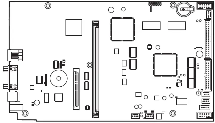 Main Logic Board: Appearance varies depending on part version.
Power Supply and Driver Board
The power supply (P/N 1-971132-9xx) delivers 24 VDC to the driver board. AC power input voltage range is 90 to 265 VAC, 45-65 Hz. Voltage and temperature are monitored and the supply is over-current protected.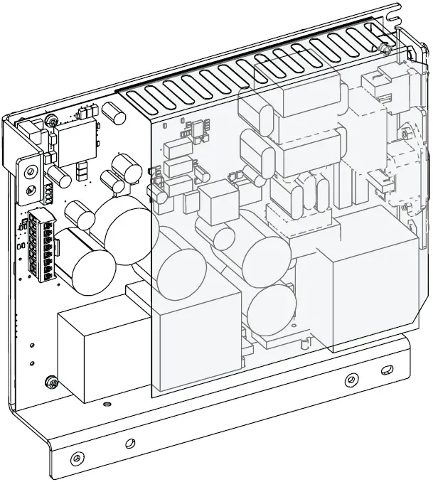 The driver board (P/N 1-971152-9xx) converts 24 VDC from the power supply to the voltages needed by other printer components. This board connects to P2 and P3 on the power supply board.
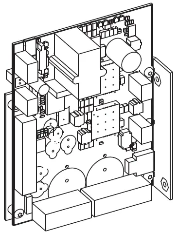
Print Module
The print module (4-inch: P/N 1-040086-9xx, or 6-inch: P/N
1-040087-9xx) includes a 203-dpi or 300-dpi printhead, a stepper motor that drives the rollers, a tear bar, and a label stop sensor that controls media feed. The stepper motor connects to P10 on the driver board. The lower label stop sensor connects to J54 on the main logic board. The upper label stop sensor connects to J55 on the main logic board.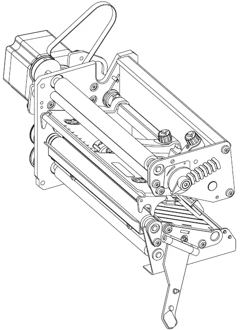 Print Module: Appearance varies depending on printhead and media width.
Printhead Part Numbers and Descriptions
| Printhead P/N | Printhead Size | Maximum Media Width |
| 1-040082-9xx | 203 dpi | 101.6 mm (4 in) |
| 1-040083-9xx | 300 dpi | 101.6 mm (4 in) |
| 1-040084-9xx | 203 dpi | 152.4 mm (6 in) |
| 1-040085-9xx | 300 dpi | 152.4 mm (6 in) |
Note:
You can also order a 400-dpi printhead (P/N 850-812-9xx) to use with the PX4i and PX6i Print Kits. For information, contact your Intermec sales representative.
Keypad and Display Assembly
The optional keypad and display assembly (P/N 1-040197-xx) includes a self-adhesive membrane switch keyboard, a self-adhesive overlay, and a printed circuit board. The entire assembly connects to J50 on the main logic board.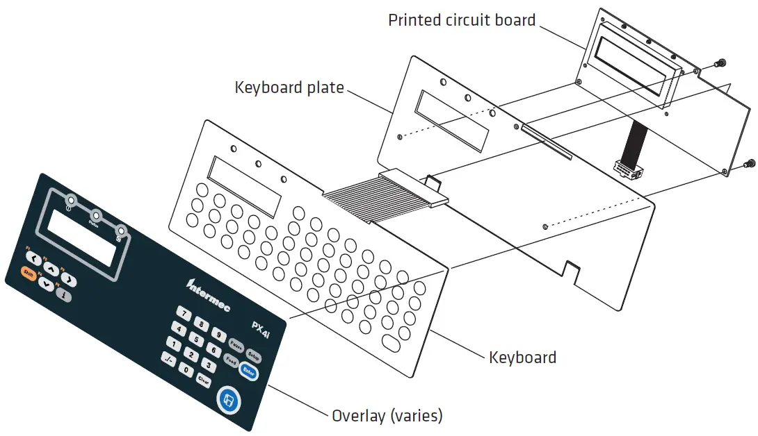 The membrane switch keyboard includes 54 keys. The Shift key provides dual functionality for each key. The keyboard connects to J2 on the printed circuit board. The self-adhesive overlay shows key locations on the keyboard. You can use your own overlays for custom applications if needed. The printed circuit board includes a 2-line LCD and three LEDs. The backlit LCD can display 16 characters (5 x 7 dots) in each line. The three LEDs indicate power, printer status, and Intermec Ready-to-Work state.
About the Option Kits
Option Kits 1, 2, and 3 include the necessary hardware for handling different types of media:
- Option Kit 1 includes hardware for use with thermal transfer ribbon. For more information, see “About the Parts in Option Kit 1” on page 14.
- Option Kit 2 includes media supply hub hardware. For more information, see “About the Parts in Option Kit 2” on page 15.
- Option Kit 3 includes hardware for self-strip printing. For more information, see “About the Parts in Option Kit 3” on page 17.
Option Kit 4 includes printer cabinet center, back, and bottom plates. For more information, see “About the Parts in Option Kit 4” on page 19.
PX Option Kit Part Numbers
| Kit Name | Part Number | Max. Media Width |
| PX4i Option Kit 1 | 1-PX4654-00x | 101.6 mm (4 in) |
| PX4i Option Kit 2 | 1-PX4654-01x | 101.6 mm (4 in) |
| PX4i Option Kit 3 | 1-PX4654-02x | 101.6 mm (4 in) |
| PX4i Option Kit 4 | 1-PX4654-04x | 101.6 mm (4 in) |
| PX6i Option Kit 1 | 1-PX6654-00x | 152.4 mm (6 in) |
| PX6i Option Kit 2 | 1-PX6654-01x | 152.4 mm (6 in) |
| PX6i Option Kit 3 | 1-PX6654-02x | 152.4 mm (6 in) |
| PX6i Option Kit 4 | 1-PX6654-04x | 152.4 mm (6 in) |
About the Parts in Option Kit 1
Option Kit 1 includes components for supplying thermal transfer ribbon to the print mechanism.
Ribbon Supply Unit
The ribbon supply unit (P/N 1-040189-xx) keeps the ribbon tight to prevent wrinkling and creasing. The adjustable hub fits different ribbon widths. Use two M4 x 8 mm Torx screws (supplied) to mount the ribbon supply unit to your printer chassis.
Ribbon Rewind Unit
The ribbon rewind unit (P/N 1-040191-xx) is powered by the print module, and rewinds used ribbon. A friction brake keeps ribbon tight as it is rewound. Use two M4 x 8 mm Torx screws (supplied) to mount the ribbon rewind unit to your printer chassis. The ribbon rewind unit includes a belt and a tension adjust gear and axle.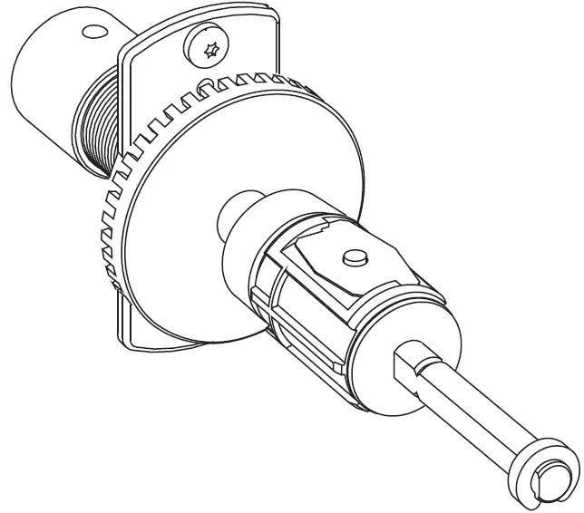 Ribbon Sensor
The ribbon sensor (P/N 1-974005-xx) determines when the ribbon supply is running low, and must be mounted at a specific location for proper operation. The sensor connects to J56 on the main logic board. Use the supplied M3 x 6 mm Torx screw to mount the sensor to your printer chassis.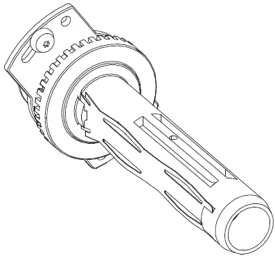 About the Parts in Option Kit 2
Option Kit 2 includes components for supplying media to the print mechanism.
3-Inch Adapter
The adapter (P/N 1-040327-xx) slides onto the media supply hub. Use this adapter for media roll cores of 80 mm (3 in) or larger.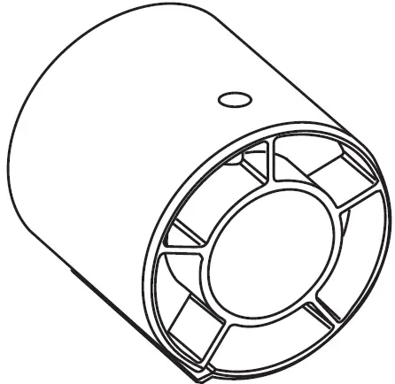 Media Supply Hub
The media supply hub (1-040060-xx) holds media rolls for the print module. Media roll cores of up to 40 mm (1.5 inches) can fit on the hub. For a PX4 hub, the maximum media width is 120 mm (4.72 in), and for a PX6 hub, the maximum width is 170 mm (6.69 in). Use four M4 x 8 mm Torx screws (supplied) to mount the media supply hub to your printer chassis.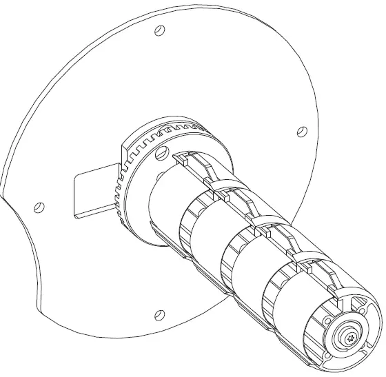
Guide Plate
When the print mechanism and the media supply hub are mounted on the same chassis panel, the guide plate (P/N 1-040296-xx) keeps the media correctly aligned with the print mechanism. Use three M4 x 8 mm Torx screws (supplied) to mount the guide plate to your printer chassis.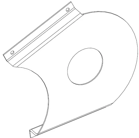 Label Slack Absorber
The label slack absorber (P/N 1-040061-xx) automatically increases or decreases tension on the media roll as media is pulled into the print module, and keeps the tension as constant as possible for smooth media feed. Use two M4 x 6 mm Torx screws (supplied) to mount the label slack absorber to your printer chassis.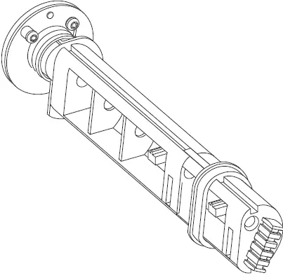 About the Parts in Option Kit 3
Option Kit 3 includes components for self-strip operation.
Liner Takeup Unit
The liner take up unit (P/N 1-040187-xx) rewinds the spent media liner and is powered by its own stepper motor. Use two M4 x 8 mm Torx screws (supplied) to mount the liner take up unit to your printer chassis.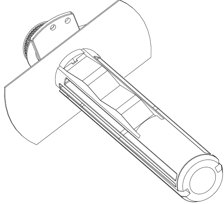 Brace
Brace
The brace (P/N 1-040317-xx) slides onto the liner take up unit and adds additional support for liner cores that are too large for the take up hub.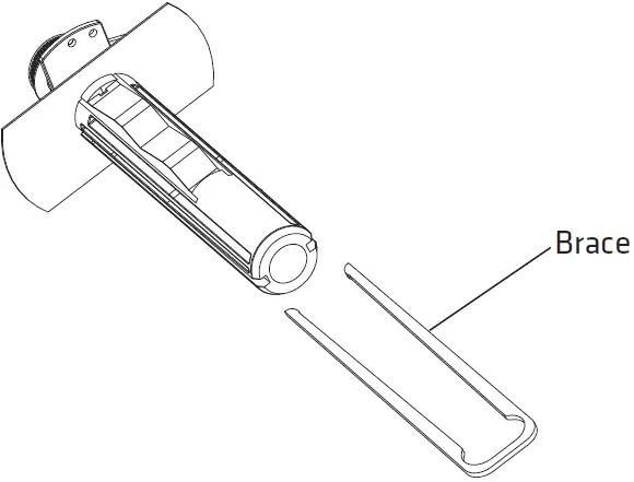 Break Shaft
The break shaft (P/N 1-040258-xx) keeps the rewound media away from other nearby components. Use the supplied M4 x 8 mm Torx screw to mount the break shaft on your printer chassis.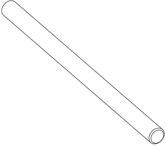 Stepper Motor
The stepper motor (P/N 1-040960-9xx) uses a pair of belts (supplied) to drive the liner take up unit and the liner drive roller in the print mechanism. Use four M4 x 8 mm Torx screws (supplied) to install the stepper motor on the motor mount. The motor connects to P11 on the driver board.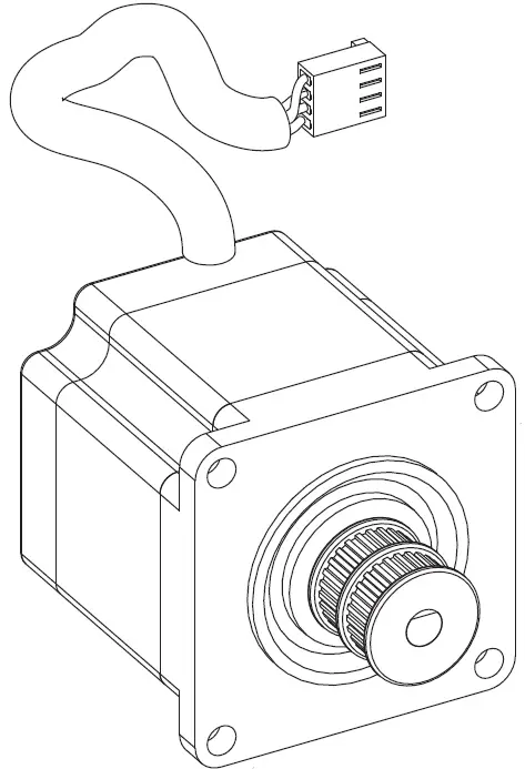
Motor Mount
The motor mount (P/N 1-040105-xx) holds the stepper motor on the printer chassis. Use three M4 x 8 mm Torx screws (supplied) to install the motor mount on the printer chassis.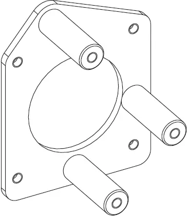 Belt Stretcher Kit
When you install the stepper motor and liner take up unit, use the belt stretcher kit (P/N 1-040239-xx) to install the belts for the liner take up unit and the liner drive roller in the print module.
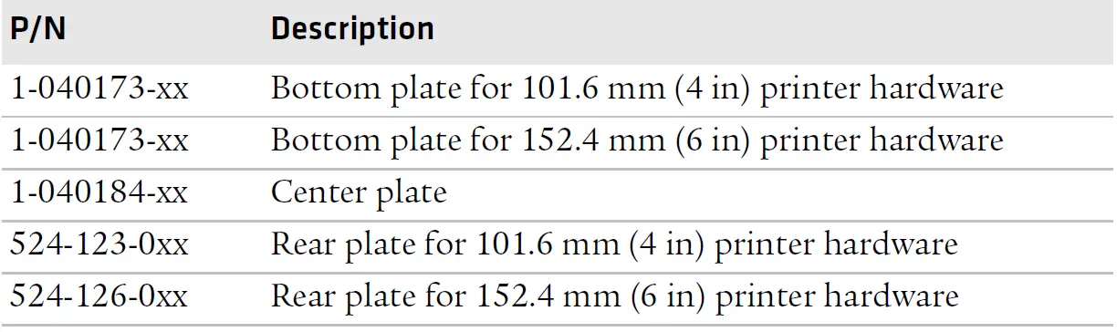
About the Parts in Option Kit 4
Option Kit 4 includes chassis parts that are pre-drilled for use with the PX4i and PX6i Print Kit components. This kit includes center, bottom, and back plates as used in the PX4i and PX6i printers.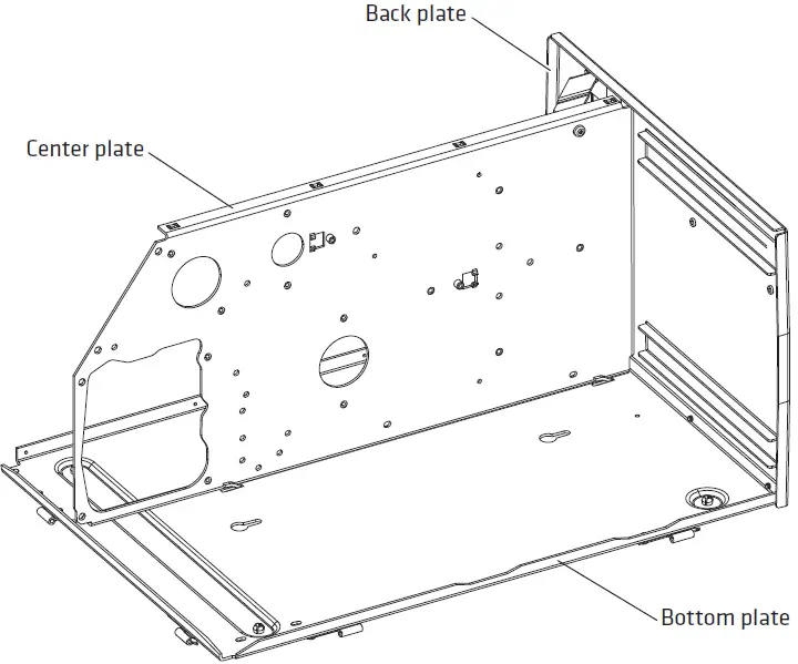 Option Kit 4 Parts: Size and appearance of parts varies depending on the kit you ordered.
Option Kit 4 Parts – Individual Part Numbers