Galaxy Equipment 177GMIX10 Planetary Stand Mixer User Manual
Parts Overview
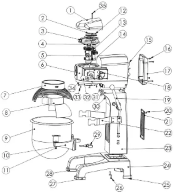
| ITEM | DESCRIPTION | # |
| 1 | Top Cover | 1 |
| 2 | Center Axle Cover | 1 |
| 3 | Bearing Cover | 1 |
| 4 | Gear Axle | 1 |
| 5 | Fork | 1 |
| 6 | Body | 1 |
| 7 | Safety Net (Out) | 1 |
| 8 | Safety Net (In) | 1 |
| 9 | Bowl | 1 |
| 10 | Arm | 1 |
| 11 | Bowl Screw | 2 |
| 12 | Two Axle Cover | 1 |
| 13 | Gear Axle II | 1 |
| 14 | Center Axle | 1 |
| 15 | Motor | 1 |
| 16 | Screw | 4 |
| 17 | Rear Cover | 1 |
| 18 | Name Plate | 1 |
| 19 | Handle | 1 |
| 20 | Screw | 4 |
| 21 | Cover | 1 |
| 22 | Bowl’s Board | 1 |
| 23 | Stand | 1 |
| 24 | Seat | 1 |
| 25 | Rubber Foot (Back) | 1 |
| 26 | Screw | 4 |
| 27 | Rubber Foot (Front) | 1 |
| 28 | Rubber Foot (Front) | 1 |
| 29 | Switch Frame for Bowl | 1 |
| 30 | Screw | 2 |
| 31 | Switch Frame for Safety Net | 1 |
| 32 | Speed Block | 1 |
| 33 | Screw | 6 |
| 34 | Inner Gear | 1 |
| 35 | Screw | 1 |
Standard Accessories
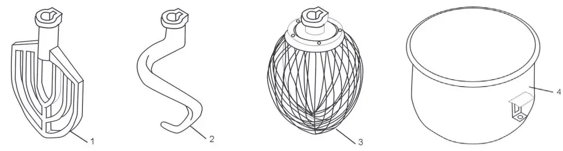
| Item | Description | Qty |
| 1 | Flat Beater | 1 |
| 2 | Dough Hook | 1 |
| 3 | Whisk | 1 |
| 4 | Bowl | 1 |
NOTES
- Any agitator is easily installed by simply raising it onto the mixing axle, and the rotating it clockwise on the shaft until it locks into place. To remove, raise the agitator on the shaft until it clears the lock and then rotate counter-clockwise and lower.
- All of the accessories are precisely fitted to the bowl, have rounded corners, and are easily removable for cleaning.
- DO NOT hose down mixer.
- DO NOT operate mixer with wet hands.
- ALWAYS unplug mixer from electrical supply prior to any maintenance or repairs.
Operation Instructions
![]() Please ensure that your power supply matches your machine
Please ensure that your power supply matches your machine
![]() For changing the speed: Please stop machine first before changing speed in order to avoid damage to the gear box. Also make sure that the bowl is in fully lifted position and the guard is closed.
For changing the speed: Please stop machine first before changing speed in order to avoid damage to the gear box. Also make sure that the bowl is in fully lifted position and the guard is closed.
- Slow Speed is the middle, dough hook setting. The knob will be facing forward.
- Medium Speed is the bottom, flat beater setting. The knob will be straight down.
- High Speed is the top, whisk setting. The knob will be straight up.
Mixing: Always use the correct attachment for the job.
![]() A. Whisk: Suitable for mixing liquids and soft ingredients, can work in all speeds. Do not run for more than 15 minutes
A. Whisk: Suitable for mixing liquids and soft ingredients, can work in all speeds. Do not run for more than 15 minutes
![]() B. Flat Beater: Suitable for mixing dry ingredients, can work in low & medium speeds only. Do not use in high speed. Do not run for more than 15 minutes
B. Flat Beater: Suitable for mixing dry ingredients, can work in low & medium speeds only. Do not use in high speed. Do not run for more than 15 minutes
![]() C. Dough Hook: Suitable for mixing dough, can work in low & medium speeds only. Do not use in high speed, do not run for more than 20 minutes. Absorption ratio must be more than 50%. Refer to mixer capacity chart.
C. Dough Hook: Suitable for mixing dough, can work in low & medium speeds only. Do not use in high speed, do not run for more than 20 minutes. Absorption ratio must be more than 50%. Refer to mixer capacity chart.
Mixer Capacity Chart
| Product | Agitator and Speed | Maximum Bowl Capacity 10 Qt. / 20 Qt. |
| Bread and Roll Dough – 60 % AR | Dough Hook – 1st only | 5 lb. / 20 lb. |
| Heavy Bread Dough – 55% AR | Dough Hook – 1st only | 3 lb. / 15 lb. |
| Pizza Dough, Thin – 40% AR | Not Recommended | – |
| Pizza Dough, Medium – 50% AR | Not Recommended | – |
| Pizza Dough, Thick – 60% AR | Not Recommended | – |
| Raised Donut Dough – 65% AR | Dough Hook – 1st and 2nd | 2 lb. / 8 lb. |
| Mashed Potatoes | Flat Beater | 5 lb. / 12.5 lb. |
| Waffle or Hot Cake Batter | Flat Beater | 4 Qt. / 8 Qt. |
| Egg Whites | Wire Whisk | 1 Qt. / 1 Qt. |
| Whipped Cream | Wire Whisk | 1 Qt. / 2 Qt. |
| Cake Batter | Flat Beater | 8 lb. / 20 lb. |
When mixing dough ( pizza, bread or bagels), check your “AR” absorption ratio – water weight divided by flour weight. Above capacities based on 12% flour moisture at 70°F water temperature. If high gluten flour is used, reduce above dough batch size by 10%.
Example: If recipe calls for 5 lb. of water and 10 lb. of flour, then 5 divided by 10 = 0.50 x 100 = 50 %AR.
- 2nd Speed should never be used on mixtures with less than 50% AR.
- Do not use attachments on hub while mixing.
When calculating the correct size mixer for your application, here are some helpful weights & measures: - 8.3 lb. = 1 gallon of water – 2.08 lb. = 1 Quart.
Troubleshooting
| Trouble | Possible Causes | Solution |
| The axles can’t work when operating the machine | Poor contact of the electrical equip- ment | Check the Plug |
| The mixing bowl is out of position | Moving direction is not correct | Change |
| Leaks oil | Sealing washer is damaged | Change |
| Difficult to move the bowl up and down | Slideway is rusted | Clean the slideway and lubricate |
| The motor is overheated and speed is down | The voltage is not enough, or incorrect speed | Check the voltage or use lower speed |
| Noise and overheating | Poor lubrication | Add or change lubrication |
| Mixer touches bowl | The mixing device or bowl deformed | Repair or change the bowl or mixing device |
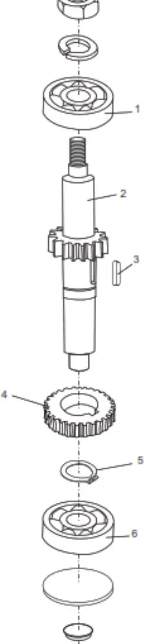
Axle Diagram
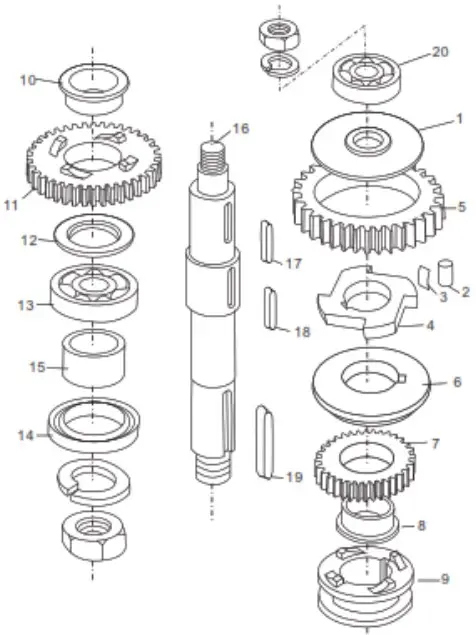
| ITEM | DESCRIPTION | # |
| 1 | Baffle | 1 |
| 2 | Roller (Ø8*16) | 4 |
| 3 | Spring | 8 |
| 4 | Engager | 1 |
| 5 | Gear Ring | 1 |
| 6 | Dividing Ring | 1 |
| 7 | Joint Gear | 1 |
| 8 | Bearing Ring | 1 |
| 9 | Joint | 1 |
| 10 | Bearing Ring | 1 |
| 11 | Joint Gear | 1 |
| 12 | Ring | 1 |
| 13 | Bearing (6205) | 1 |
| 14 | Oil Seal (Pd30*45*10) | 1 |
| 15 | Sleeve | 1 |
| 16 | Axle | 1 |
| 17 | Key (6*14) | 1 |
| 18 | Key (5*35) | 2 |
| 19 | Key (6*30) | 1 |
| 20 | Bearing (6003) | 1 |
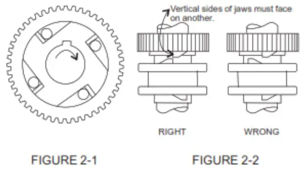
NOTES:
- Be sure to install in correct position (see Figure 2-1) and lubricate all of the pins in the sleeve drive when assembling.
- Joint (9) must always be raised and lowered smoothly. Be sure joint sleeve is positioned as showin in Figure 2-2.
- Check Oil Seal (14) if oil leaks from drip cup.
Gear Axle Diagram
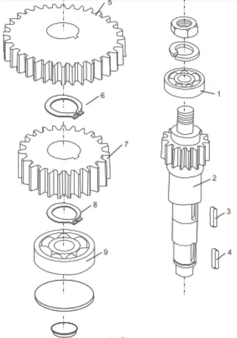
| ITEM | DESCRIPTION | # |
| 1 | Bearing (6201) | 1 |
| 2 | Gear Axle | 1 |
| 3 | Key (5*11) | 1 |
| 4 | Key (5*11) | 1 |
| 5 | Gear | 1 |
| 6 | Stop Ring | 1 |
| 7 | Gear | 1 |
| 8 | Stop Ring | 1 |
| 9 | Bearing (6201) | 1 |
NOTES:
- The gear shaft and gear shaft I are above the center of the shaft unit. (see Figure 3-1)
- C-type stop ring (6/8) has to be fixed when reassembling.
- Be sure that the keys are inserted for each gear

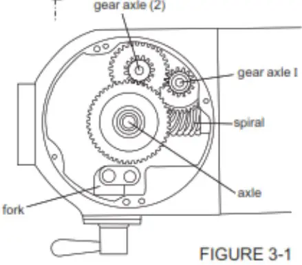
Gear Axle I
| ITEM | DESCRIPTION | # |
| 1 | Bearing (6201) | 1 |
| 2 | Gear Axle | 1 |
| 3 | Key (5*14) | 1 |
| 4 | Gear | 1 |
| 5 | Stop Ring | 1 |
| 6 | Bearing (6201) | 1 |
Turning Plate & Mixing Axle Diagram
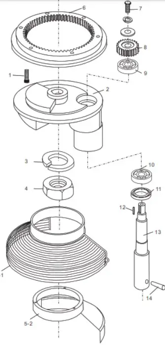
| ITEM | DESCRIPTION | # |
| 1 | Screw (M6*25) | 6 |
| 2 | Turning Plate | 1 |
| 3 | Ring | 1 |
| 4 | Nut (M18) | 1 |
| 5-1 | Safety Net (Locomotion) | 1 |
| 5-2 | Safety Net (Immobility) | 1 |
| 6 | Inner Gear | 1 |
| 7 | Screw (M8*15) | 1 |
| 8 | Planetary Gear | 1 |
| 9 | Bearing (6203) | 1 |
| 10 | Bearing (6204) | 1 |
| 11 | Oil Seal (Pd25*50*10) | 1 |
| 12 | Key (5*18) | 1 |
| 13 | Mixing Axle | 1 |
| 14 | Pin | 1 |
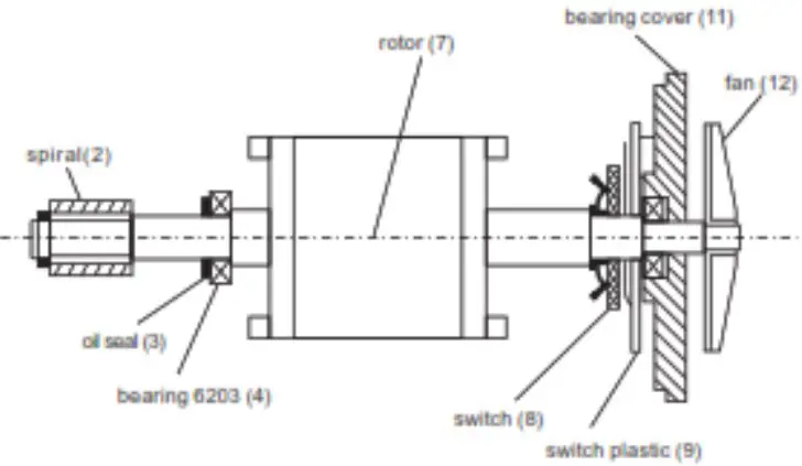
Motor Unit
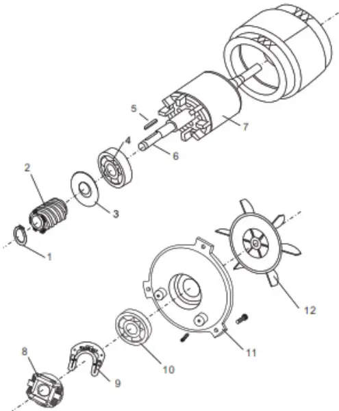
| ITEM | DESCRIPTION | # |
| 1 | Stop Ring | 1 |
| 2 | Spiral | 1 |
| 3 | Oil Seal | 1 |
| 4 | Bearing (6203) | 1 |
| 5 | Key 4*22 | 1 |
| 6 | Axle | 1 |
| 7 | Rotor | 1 |
| 8 | Switch | 1 |
| 9 | Switch Plastic | 1 |
| 10 | Bearing (6203) | 1 |
| 11 | Bearing Cover | 1 |
| 12 | Fan | 1 |
NOTES:
- If the motor does not work, first verify the power source and connection. Next, check for damaged or faulty wiring or connections inside the mixer. The motor may not be working because of inappropriate voltage, broken wires, a defective capacitor, or a defective centrifugal governor. Motor damage may also be caused by bowl overload during mixing.
- Motor set includes motor axle (6), rotor (7) and stator.
- Figure 5-1 is a component system diagram of the motor.

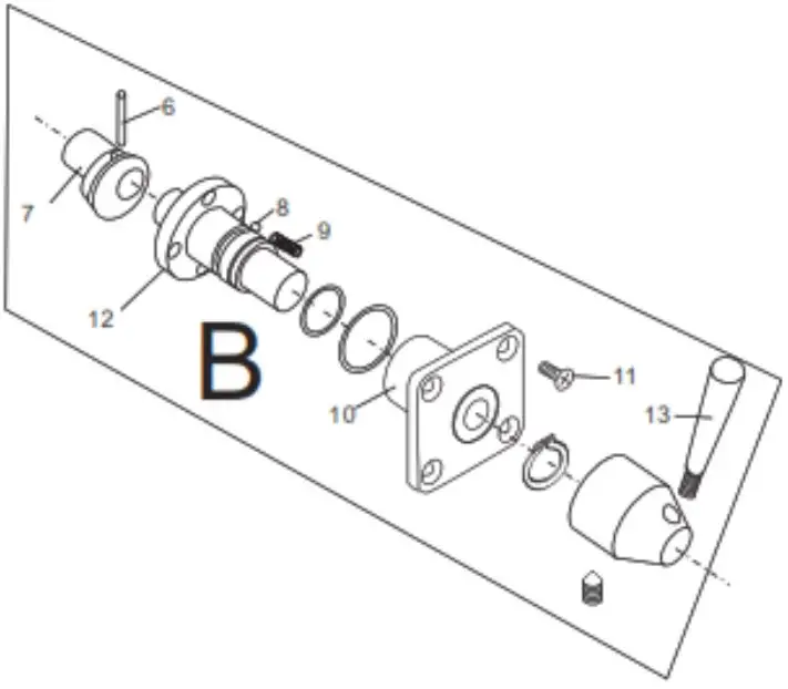
Fork & Speed Shaft
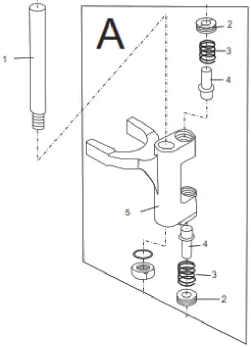
| ITEM | DESCRIPTION | # | |
| 1 | Axle | 1 | |
| A | 2 | Nut | 1 |
| 3 | Spring | 1 | |
| 4 | Shaft | 1 | |
| 5 | Fork | 1 | |
| B | 6 | Pin | 1 |
| 7 | Eccentricity Knot | 1 | |
| 8 | Steel Ball | 1 | |
| 9 | Speed Spring | 1 | |
| 10 | Screw | 1 | |
| 11 | Shaft | 1 | |
| 12 | Handle | 1 | |
NOTES:
- The speed selector/shifting mechanism is designed for simplicity and reliability. It features three mixing speeds.
- Speed selection is made by aligning the pointer of the shifter handle with the proper number on the shift selector. Stop the mixer before making any speed changes.
- Apply sealant to the shift selector assembly and install it.


