DIGILENT PmodIOXP I-O Expansion Module
PmodIOXP Product Information
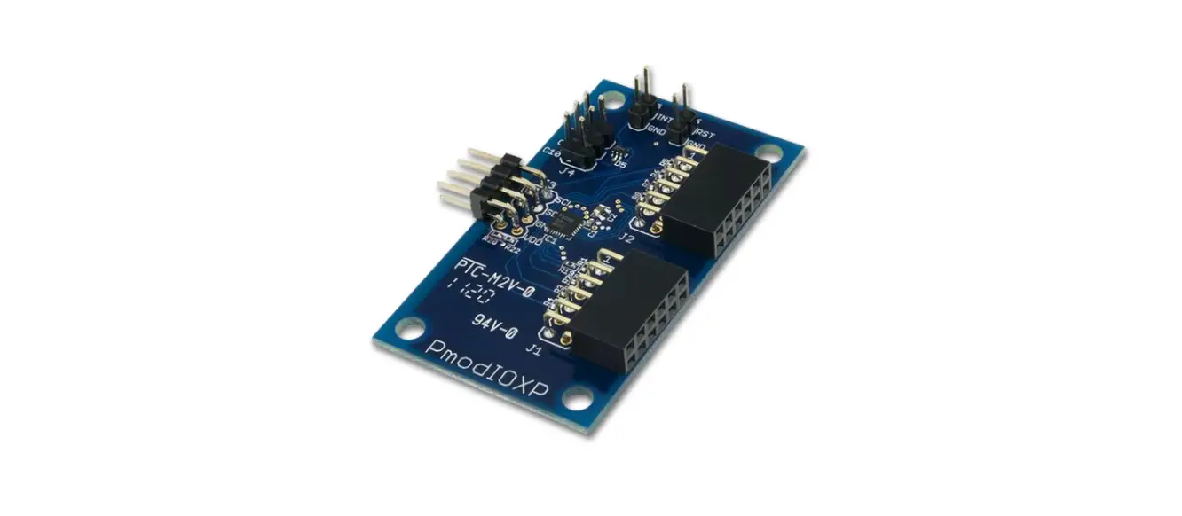
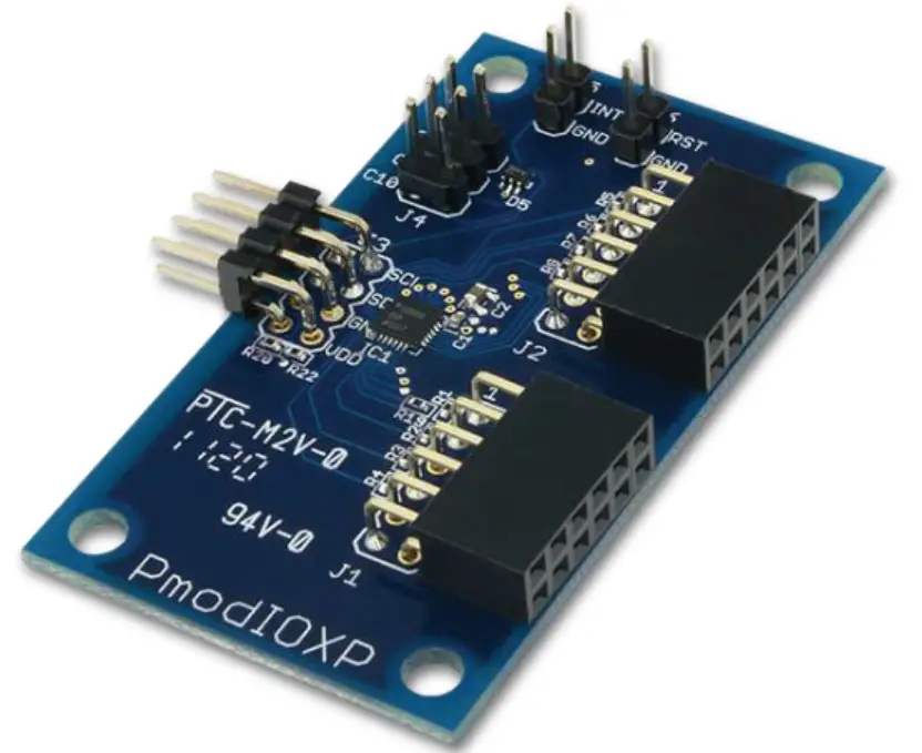
The Digilent PmodIOXP is an Input/Output Expansion module capable of providing up to 19 additional IO pins. It is designed to be operated at 3.3V.
Pinout Description
| Pin | Signal | Description |
|---|---|---|
| 1 & 5 | SCL | Serial Clock |
| 2 & 6 | SDA | Serial Data |
| 3 & 7 | GND | Ground Power Supply |
| 4 & 8 | VCC | Power Supply (3.3V/5V) |
Physical Dimensions
The pins on the pin header are spaced 100 mil apart. The PCB is 1.3 inches long on the sides parallel to the pins on the pin header and 2.3 inches long on the sides perpendicular to the pin header.
Overview
The Digilent PmodIOXP is an Input/Output Expansion module capable of providing up to 19 additional IO pins.
Features include:
- Communicates via the I²C interface
- 16-element FIFO for event recording
- 19 configurable I/Os
- Built-in keypad decoding for matrices up to 11×8
- PWM generator
- Open-drain interrupt output
- Two programmable logic blocks
- Debouncing on I/Os
The PmodIOXP.
Functional Description
The PmodIOXP utilizes Analog Devices’ ADP5589. Through the use of I²C, users may expand from the two I/O pins required to nearly 10 times the amount of available I/O.
Interfacing with the Pmod
The PmodIOXP communicates with the host board via the I²C protocol. By sending out the 7-bit slave address of 0110100 and a read or write bit (1/0), users may then read or write to a specific register to configure the Pmod to enable interrupts or read the status of GPIO pins.
DOC#: 502-219
Downloaded from Arrow.com.
Copyright Digilent, Inc. All rights reserved. Other product and company names mentioned may be trademarks of their respective owners.
PmodIOXPTM Reference Manual
Pinout Description Table
| Pin | Signal | Description |
| 1 & 5 | SCL | Serial Clock |
| 2 & 6 | SDA | Serial Data |
| 3 & 7 | GND | Power Supply Ground |
| 4 & 8 | VCC | Power Supply (3.3V/5V) |
Any external power applied to the PmodIOXP must be within 1.65V and 3.6V; it is recommended that Pmod is operated at 3.3V.
Physical Dimensions
The pins on the pin header are spaced 100 mil apart. The PCB is 1.3 inches long on the sides parallel to the pins on the pin header and 2.3 inches long on the sides perpendicular to the pin header.
Copyright Digilent, Inc. All rights reserved. Other product and company names mentioned may be trademarks of their respective owners.
Downloaded from Arrow.com.


