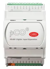
CAREL UXP Microchiller Expansion Module
Key
| Key: | |
| 1 | Power supply connector [G (+), G0 (-)] |
| 2 | Digital inputs |
| 3 | RS485 serial port (GND, T+, T-) |
| 4 | Red LED and green LED to indicate the operating status |
| 5 | Modbus address and baud rate setting |
| 6 | IDC1 is the common for inputs ID1 … ID8. IDC2 is the common for inputs ID9 … ID16 |
General characteristics
UXP is an expansion module developed by Carel to handle an higher number of digital input. Module is driven by the Modbus (RTU) protocol using a serial communication (RS485). Input can be handled by the expansion are:
- Fast digital inputs with voltage-free contact to correctly handle high speed inputs. E.g. to monitor fan speed;
- Digital inputs with voltage-free contacts.
Power supply
When installing an expansion card, a safety isolating transformer with a minimum rating of 5W or 24Vdc. source must be used. It is recommended to separate the UXP device from the power supply to other elec-trical devices (contactors and other electromechanical components) in the electrical panel. Make sure that the G and G0 references on all the cards mounted in the panel have the same polarity. (G0 reference must be used on every card).
Technical specifications
Mechanical specifications
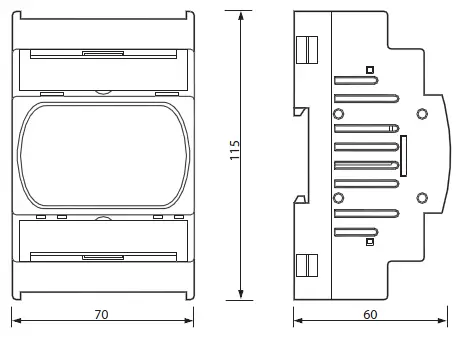
Dimensions
UXP can be mounted on 4 DIN modules, 115x70x60 mm;
Plastic enclosure
- DIN rail mounting in accordance with DIN 43880 and CEI EN 50022;
- material: technopolymer;
- self-extinguishing: V0 (in compliance with UL94) and 960 °C (in compliance with IEC 695);
- ball pressure test:125 °C;
- comparative tracking index: ≥ 250 V;
- colour: RAL7035 grey;
- cooling vent holes.
Electrical specifications
| Power | 24 Vac/Vdc +10%/-15% 50/60 Hz, UXPB********* Max power input: 6 W SELV (Class 2 – UL) |
| Terminal block | with plug-in screw/fixed screw connectors – max. voltage: 250 Vac cable cross-section: min. 0.5 mm2 – max. 2.5 mm2 |
| CPU | single chip 32 bits; 48 MHz |
| Operation delay time | 0.5 s |
| Communication frame | baud rate 9600 to 57600 bit/s; stop bits 2; parity none |
Digital inputs
- number and type: 8 not opto-isolated D.I. max freq.: 500 Hz UXP*****2****
- number and type: 16 not opto-isolated D.I. max freq.: 500 Hz UXP*****3****
Note: for general purpose DIs, there is an internal power supply for the DI part, these only support external voltage-free contacts.
Warning:
- If the length exceeds 10 m, use a shielded cable with the shield earthed. In any case, the maximum length permitted is 30 m. Length > 10 m a shielded cable with the shield earthed is required;
- Please keep the probe and digital input cables as far away as possible from power cables, to avoid pos-sible electromagnetic noise.
Using the dipswitches to set the address and baud rate
It is recommended to power down the board before changing the dipswitch settings
Important: the baud must be rebooted for the new baud rate and address settings to take effect.
The board is equipped with 4 dipswitches that are used to the configuration with the 4 dipswitches all set to 0, the board is set with address 1 and 19200 8N2 as the communication parameters. This configuration has been developed for use in the system configuration phase or to assist in identifying communication errors. The serial address is set using dipswitches 1 and 2. To allow for a larger set of values, there is also an offset variable, default value 0. For information on this variable (address and limits), see the list of UXP Modbus variables.
Expansion dimensions
Meaning of signal LEDs
| red LED | green LED | meaning |
| — | ON | Always on when power is connected |
| — | Blinking | Probe error alarm |
| OFF | — | Normal communication |
| Blinking | — | No communication for more than 30 s |
When dipswitches 1 and 2 are set to 1, 2 or 3, the UXP address is the sum of the value set by the dip-switches and the value of the offset variable.
| Serial address |
| 1 + offset (default) |
| 2 + offset |
| 3 + offset |
Dipswitches 3 and 4 set the baud rate, as shown in the figure below:
| Baud rate |
| 19200 (default) |
| 9600 |
| 38400 |
| 57600 |
Configuration examples
| Offset | Address | Baudrate |
| any value | 1 | 19200 |
| 0 | 1 | 19200 |
| 0 | 2 | 57600 |
| 40 | 2 + 40 = 42 | 57600 |
| 0 | 3 | 19200 |
| 20 | 3 + 20 = 23 | 19200 |
| 20 | 3 + 20 = 23 | 9600 |
Setting the communication parameters
To set the communication parameters, the serial transmission configuration variable needs to be set via serial communication (see Tab. 1).
Example: if the variable is set to 5, then the configuration is 8, Even, 1. For information on this variable (address and limits), see the list of UXP Modbus variables.
IMPORTANT: if the communication parameter settings are changed, the board must be rebooted to make them active.
| Value | Configuration |
| 0 (default) | 8, None, 2 |
| 1 | 8, None, 1 |
| 2 | 8, Odd, 2 |
| Value | Configuration |
| 3 | 8, Odd,1 |
| 4 | 8, Even, 2 |
| 5 | 8, Even, 1 |
- UXPCON0020 (for 8 inputsUXP*****2**** version);
- UXPCON0030 (per 16 inputs UXP*****3**** version).Following codes are available, sold separately, for the connector kits:
Other specifications
| Storage conditions | -40T70 °C, 90% r.H. non-condensing |
| Operating conditions | -40T60 °C, 90% r.H. non-condensing |
| Index of protection | IP00 |
| Pollution degree | 3 |
| Overvoltage category | III (based on external safety transformer or SMPS) |
| Classification according to protection against electric shock | Class III |
| PTI of insulating materials | 100 V |
| Period of electric stress across insulating parts | long |
| Type of actions | 1 |
| Category of resistance to heat and fire | D (UL94 – V0) category |
| EMC level | Industrial |
| Rated impulse voltage | 800 V |
| Software class and structure | Class A |
Warning: for applications subject to strong vibrations (1.5 mm pk-pk 10 to 55 Hz), it is recommended to use cable ties to secure the cables connected to the UXP around 3 cm from the connectors. CAREL reserves the right to modify the features of its products without prior notice.


