Avalue CCD-10WR2 Industrial Panel PC
Product Information
Product Name:
CCD-10WR2 Panel PC
Description:
The CCD-10WR2 Panel PC is a 10.1-inch device designed for various industrial applications. It comes equipped with an ACP-RK3568 hardware configuration.
Copyright:
Copyright 2022 Avalue Technology Inc., ALL RIGHTS RESERVED. Part No. E2017R127A0R
FCC Compliance:
The device complies with Part 15 of the FCC rules. It is required to use a Unshielded-type power cord to meet FCC emission limits and prevent interference to nearby radio and television reception. Shielded cables are recommended to connect I/O devices to this equipment.
Safety Precautions
- Always completely disconnect the power cord from your chassis before working with the hardware.
- Do not make connections while the power is on.
- Use a grounding wrist strap at all times to remove any static charge before touching the CPU card.
- Place all electronic components in a static-dissipative surface or static-shielded bag when they are not in the chassis.
Product Usage Instruction
Getting Started:
- Disconnect the power cord from the chassis before working with the hardware.
- Ground yourself to remove any static charge before touching the CPU card.
- Place all electronic components in a static-dissipative surface or static-shielded bag when they are not in the chassis.
Packing List
- CCD-10WR2 Panel PC
- Power adapter
- Power cord
System Specifications:
The system specifications are not provided in the text-extract.
FCC
Federal Communication Commission Interference Statement
THIS DEVICE COMPLIES WITH PART 15 OF THE FCC RULES. OPERATION IS SUBJECT TO THE FOLLOWING TWO CONDITIONS: (1) THIS DEVICE MAY NOT CAUSE HARMFUL INTERFERENCE AND (2) THIS DEVICE MUST ACCEPT ANY INTERFERENCE RECEIVED, INCLUDING INTERFERENCE THAT MAY CAUSE UNDESIRED OPERATION.
Note: This equipment has been tested and found to comply with the limits for a Class A digital device, pursuant to Part 15 of FCC Rules. These limits are designed to provide reasonable protection against harmful interference in a residential installation. This equipment generates, uses and can radiate radio frequency energy and, if not installed and used in accordance with the instruction, may cause harmful interference to radio communications. However, there is no guarantee that interference will not occur in a particular installation. If this equipment does cause harmful interference to radio or television reception, which can be determined by turning the equipment off and on, the user is encouraged to try to correct the interference by one or more of the following measures:
- Reorient or relocate the receiving antenna.
- Increase the separation between the equipment and receiver.
- Connect the equipment into an outlet on a circuit different from that to which the receiver is connected.
- Consult the dealer or an experienced radio/TV technician for help.
Notice:
- A Unshielded-type power cord is required in order to meet FCC emission limits and also to preventinterference to the nearby radio and television reception. It is essential that only the suppliedpower cord by used.
- Use only shielded cables to connect I/O devices to this equipment.
- Changes or modifications not expressly approved by the party responsible for compliance couldvoid the user’s authority to operate the equipment.
FCC RF Radiation Exposure Statement
This Wireless LAN radio device has been evaluated under FCC Bulletin OET 65 and found compliant to the requirements as set forth in CFR 47 Sections 2.1091, 2.1093, and 15.247 (b) (4) addressing RF Exposure from radio frequency devices. The radiated output power of this Wireless LAN device is far below the FCC radio frequency exposure limits. Nevertheless, this device shall be used in such a manner that the potential for human contact during normal operation is minimized. When nearby persons has to be kept to ensure RF exposure compliance, in order to comply with RF exposure limits established in the ANSI C95.1 standards, the distance between the antennas and the user should not be less than 20 cm.
WARNING
- CAUTION – Use suitable mounting apparatus to avoid risk of injury.”
- “CAUTION – This is a Class A product. In a domestic environment this product may cause radio interference in which case the user may be required to take adequate measures”
- “CAUTION –Risk of explosion if battery is replaced by an incorrect type. Dispose of used batteries according to the instructions.”
- “CAUTION – Use a power cord that matches the voltage of the power outlet, which has been approved and complies with the safety standard of your particular country.”
- “WARNING – To avoid risk of electric shock, this equipment must only be connected to a supply mains with protective earth.”
Getting Started
Safety Precautions
- Warning!
Always completely disconnect the power cord from your chassis whenever you work with the hardware. Do not make connections while the power is on. Sensitive electronic components can be damaged by sudden power surges. Only experienced electronics personnel should open the PC chassis. - Caution!
Always ground yourself to remove any static charge before touching the CPU card. Modern electronic devices are very sensitive to static electric charges. As a safety precaution, use a grounding wrist strap at all times. Place all electronic components in a static-dissipative surface or static-shielded bag when they are not in the chassis.
Packing List
- 1 x CCD-10WR2 Panel PC
- 1 x Power adapter
- 1 x Power cord
System Specifications
| Component | |
| Mother Board | ACP-RK3568 |
| CPU | RK3568_Quad-core Cortex-A55 up to 2.0GHz_ Mali-G52 GPU |
| Memory | 2GB DDR4 on board |
| Power Supply | DC in |
| Camera | 2MP Camera with Digital Microphone |
| Wireless LAN | AW-CM276NF_ac/a/b/g/n_2x2 |
| Bluetooth | 5.0 |
| Operating System | Android 11, Debian 10 |
| Storage | |
| Other Storage Device | 32GB eMMC |
| Panel | |
| LCD Panel | 10.1” MIPI Panel |
| Resolution | 800 x 1280 |
| Touch Screen | 10.1” USB P-CAP Touch |
| Touch Controller | ILI_2511 |
| External I/O | |
| DC in Power jack | JDCIN1: Power Jack_90D Pwr-in 12V~24V |
| HDMI Port | JHDMI1: HDMI Port_90D |
| USB Port | JUSB1: USB Type A Host (3.0)_90D JUSB2: USB Type A Host (3.0)_90D |
| Lan Port | JLAN1: 10/100/1000 Lan port_90D |
| Audio Port | JHP1: Headphone Jack_90D |
| Reset button | Reset button_90D |
|
Speaker | 1.3W Speaker x1 (Left side) PS: From the HW side, only one issue needs to be pointed out here, because the serious shortage of TI TPA2012D2RTJT, we decided to put only 1 Audio Amplifiers instead. But of course, after the supply chain is getting stable later on, we will follow our original specification with dual Audio Amplifiers. |
| Mechanical | |
| Power Type | 12V~24V wide voltage DC input |
| Power Connector Type | DC jack |
| Dimension | 260.86 x 174.74 x 34 mm |
| Weight | 0.7 kg |
| Fanless | Yes |
| OS Support | Androd 11 / Debian 10 |
| Reliability | |
| EMI Test | CE FCC class B, RED |
| Safety | 2014/35/EU EN 62368-1: 2014+A11: 2017 (Second Edition) Low Voltage Directive |
|
Dust and Rain Test | 1. PSD: 0.00454G²/Hz, 1.5 Grms 2. Operation mode 3. Test Frequency: 5-500Hz 4. Test Axis: X,Y and Z axis 5. 30 minutes per each axis 6. IEC 60068-2-64 Test:Fh 7. Storage : CF or SSD |
|
Vibration Test | 1 Test Acceleration : 2G 2 Test frequency : 5~500 Hz 3 Sweep:1 Oct/ per one minute. (logarithmic) 4 Test Axis : X,Y and Z axis 5 Test time :30 min. each axis 6 System condition : Non-Operating mode 7. Reference IEC 60068-2-6 Testing procedures |
|
Mechanical Shock Test | 1. PSD: 0.026G²/Hz, 2.16 Grms 2. Non-operation mode 3. Test Frequency: 5-500Hz 4. Test Axis: X,Y and Z axis 5. 30 min. per each axis 6. IEC 60068-2-64 Test:Fh |
|
Drop Test | 1. Wave form:Half Sine wave 2. Acceleration Rate:10g for operation mode 3. Duration Time:11ms 4. No. of Shock:Z axis 300 times 5. Test Axis: Z axis 6. Operation mode 7. Reference IEC 60068-2-29 Testing procedures Test Eb : Bump Test |
| Operating Temperature | 1 One corner , three edges, six faces 2 ISTA 2A, IEC-60068-2-32 Test:Ed |
| Operating Humidity | 0°C ~ 40°C |
| Storage Temperature | 40°C @ 95% Relative Humidity, Non-condensing |
| Other Test | -20°C ~ 60°C |
Note: Specifications are subject to change without notice.
System Overview
Bottom View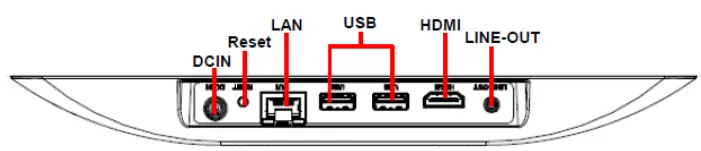
| Connectors | ||
| Label | Function | Note |
| LINE-OUOT | Audio line-out connector | |
| HDMI | HDMI connector | |
| USB | 2 x USB 3.0 connector | |
| LAN | RJ-45 Ethernet | |
| Reset | Reset button | |
| DCIN | DC power-in connector |
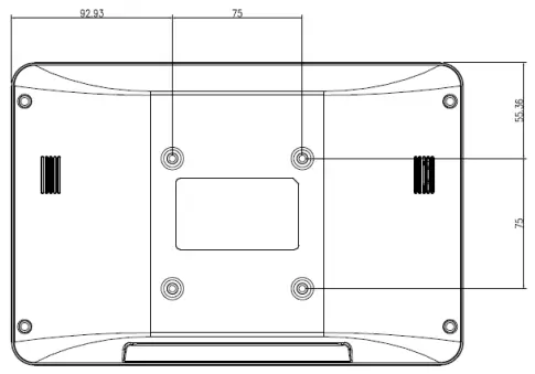
System Dimensions
Front and Rear side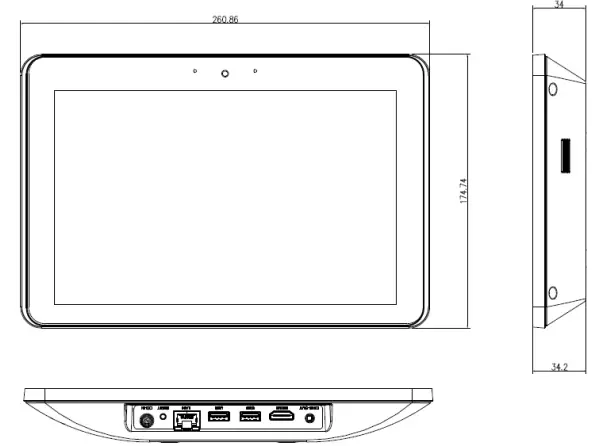
Hardware Configuration
For advanced information, please refer to:
- ACP-RK3568 included in this manual.
Note: If you need more information, please visit our website: http://www.avalue.com.tw
ACP-RK3568 Overviews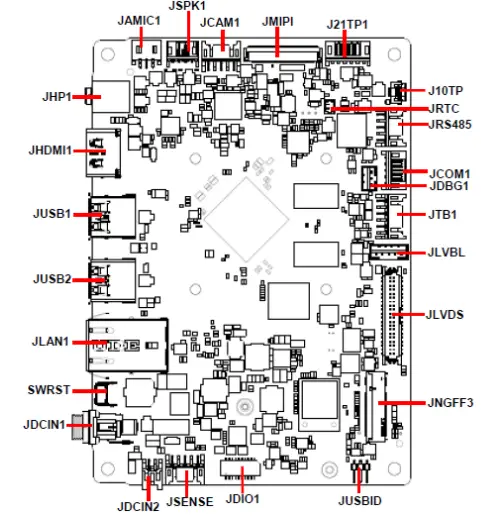
ACP-RK3568 Connector list
| Jumpers | ||
| Label | Function | Note |
| JUSBID | OTG ID select | 3 x 1 header, pitch 2.00 mm |
| Connectors | ||
| Label | Function | Note |
| JHP1 | Audio line-out connector | |
| JHDMI1 | HDMI connector | |
| JUSB1/2 | 2 x USB 3.0 connector | |
| JLAN1 | RJ-45 Ethernet connector | |
| JDCIN1 | DC Power-in connector | |
| JDCIN2 | DC Power-in connector | 2 x 2 wafer, pitch 2.00 mm |
| J21TP1 | 21” Touch Panel connector | 6 x 1 FPC, pitch 0.50 mm |
| J10TP | 10” Touch Panel connector | 6 x 1 FPC, pitch 0.50 mm |
| JSPK1 | Speaker connector | 4 x 1 wafer, pitch 2.00 mm |
| SWRST | Reset Button | |
| JNGFF3 | M.2 B-Key socket for WWAN | |
| JRTC | RTC Battery connector | 2 x 1 wafer, pitch 1.25 mm |
| JSENSE | Sensor connector | 5 x 2 wafer, pitch 2.00 mm |
| JDIO1 | General purpose I/O connector | 10 x 2 wafer, pitch 1.00 mm |
| JCAM1 | Camera connector | 5 x 2 wafer, pitch 2.00 mm |
| JCOM1 | Serial port 1 connector | 5 x 1 wafer, pitch 2.00 mm |
| JRS485 | RS-485 connector | 5 x 2 wafer, pitch 2.00 mm |
| JTB1 | Touch button board connector | 6 x 2 wafer, pitch 2.00 mm |
| JAMIC1 | A-MIC connector | 3 x 1 wafer, pitch 2.00 mm |
| JMIPI | MIPI Port | 40 x 1 FPC, pitch 0.30 mm |
| JDBG1 | Debug connector | 3 x 1 wafer, pitch 2.00 mm |
| JLVDS | LVDS connector | 40 x 1 FPC, pitch 0.50 mm |
| JLVBL | Backlight connector | 5 x 1 wafer, pitch 2.00 mm |
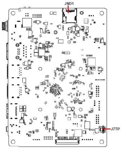
| JSD1 | Micro SD card slot | |
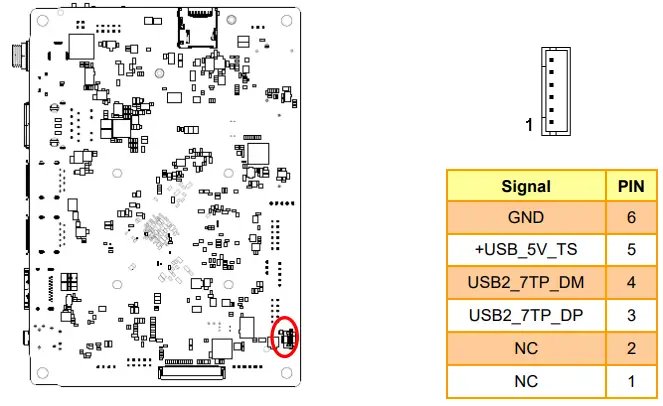
| J7TP1 | 7” Touch Panel connector | 6 x 1 FPC, pitch 0.50 mm |
ACP-RK3568 Jumpers & Connectors settings
OTG ID select (JUSBID)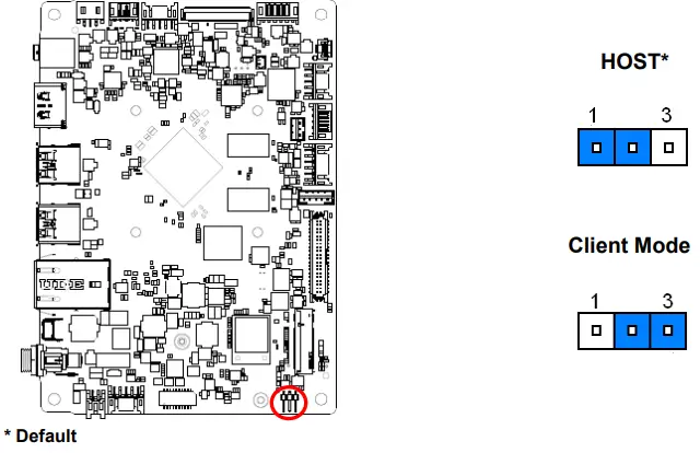
Touch button board connector (JTB1)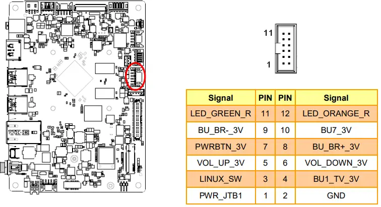
General purpose I/O connector (JDIO1)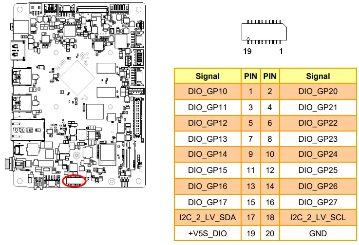
RS-485 connector (JRS485)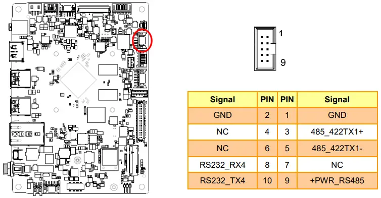
Camera connector (JCAM1)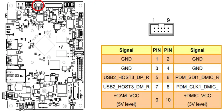
A-MIC connector (JAMIC1)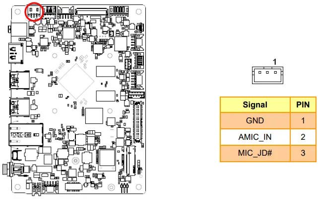
DC Power-in connector (DCIN2)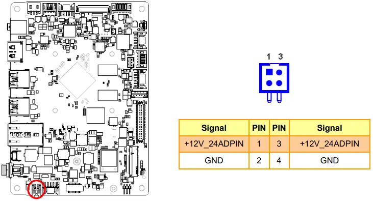
Speaker connector (JSPK1)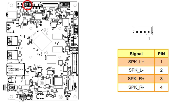
10” Touch Panel connector (J10TP)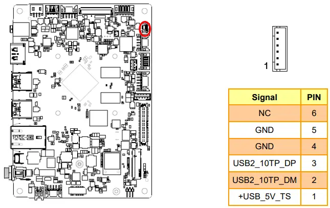
21” Touch Panel connector (J21TP1)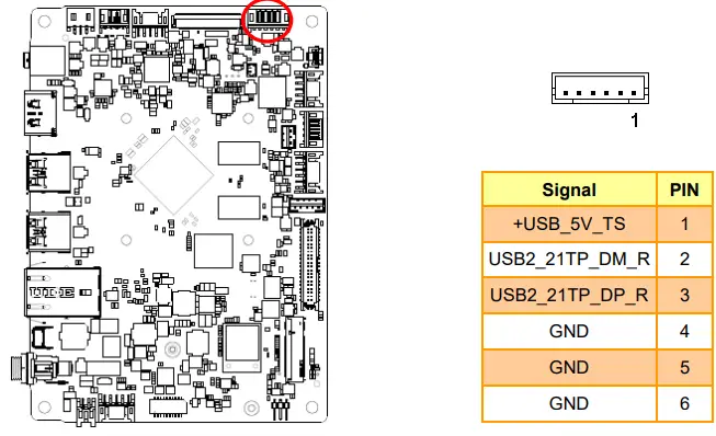
Sensor connector (JSENSE)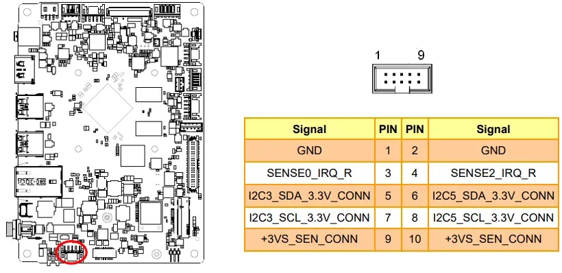
Debug connector (JDBG1)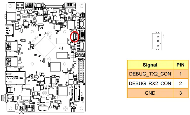
Serial port 1 connector (JCOM1)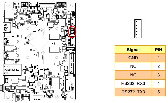
RTC Battery connector (JRTC)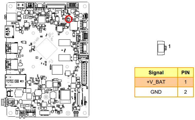
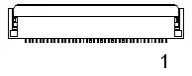
LVDS connector (JLVDS)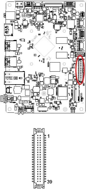
| Signal | PIN | PIN | Signal |
| +V3.3S_LVDS | 2 | 1 | +5V_LVDS |
| +V3.3S_LVDS | 4 | 3 | +5V_LVDS |
| NC | 6 | 5 | NC |
| GND | 8 | 7 | GND |
| TXO1+ | 10 | 9 | TXO0+ |
| TXO1- | 12 | 11 | TXO0- |
| GND | 14 | 13 | GND |
| TXO3+ | 16 | 15 | TXO2+ |
| TXO3- | 18 | 17 | TXO2- |
| GND | 20 | 19 | GND |
| TXE1+ | 22 | 21 | TXE0+ |
| TXE1- | 24 | 23 | TXE0- |
| GND | 26 | 25 | GND |
| TXE3+ | 28 | 27 | TXE2+ |
| TXE3- | 30 | 29 | TXE2- |
| GND | 32 | 31 | GND |
| TXEC+ | 34 | 33 | TXOC+ |
| TXEC- | 36 | 35 | TXOC- |
| GND | 38 | 37 | GND |
| +11V2S_BL | 40 | 39 | +11V2S_BL |
MIPI Port (JMIPI)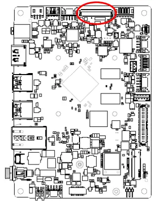
| Signal | PIN |
| +3VS_DSI | 1 |
| +3VS_DSI | 2 |
| +3VS_DSI | 3 |
| GND | 4 |
| DSI_RESET#_3V3 | 5 |
| NC | 6 |
| GND | 7 |
| MDSI_A_DN0_R | 8 |
| MDSI_A_DP0_R | 9 |
| GND | 10 |
| MDSI_A_DN1_R | 11 |
| MDSI_A_DP1_R | 12 |
| GND | 13 |
| MDSI_A_CLKN_R | 14 |
| Signal | PIN |
| MDSI_A_CLKP_R | 15 |
| GND | 16 |
| MDSI_A_DN2_R | 17 |
| MDSI_A_DP2_R | 18 |
| GND | 19 |
| MDSI_A_DN3_R | 20 |
| MDSI_A_DP3_R | 21 |
| GND | 22 |
| NC | 23 |
| NC | 24 |
| GND | 25 |
| NC | 26 |
| NC | 27 |
| NC | 28 |
| PANEL_LEDK | 29 |
| GND | 30 |
| PANEL_LEDK | 31 |
| PANEL_LEDK | 32 |
| NC | 33 |
| NC | 34 |
| NC | 35 |
| NC | 36 |
| NC | 37 |
| PANEL_LEDA | 38 |
| PANEL_LEDA | 39 |
| PANEL_LEDA | 40 |
Backlight connector (JLVBL)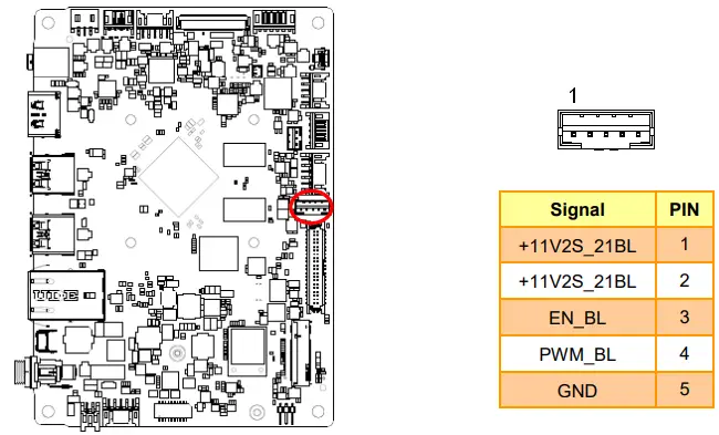
Touch Panel connector (J7TP1)