EMERSON EtherNet-IP Aventics Bus Coupler CMS B-Design
About this documentation
This documentation contains important information on the safe and appropriate assembly, operation, and maintenance of the bus coupler and how to remedy simple malfunctions yourself.
Read these instructions carefully, especially section g 2. Notes on safety before you start working with the bus coupler.
Required and supplementary documentation
- Only commission the product once you have obtained the following documentation and understood and complied with its contents.
Table 1: Required and supplementary documentation
| Title | Document number | Document type |
| Valve system documentation HF04 D-SUB | R412015493 | Instructions |
| Valve system documentation HF03-LG | R412008233 | Instructions |
| Valve system documentation CD01/02-PI | R412012449 | Instructions |
| Module extension documentation B-design stand-alone | R412008961 | Instructions |
| System documentation |
Further information on the components can be found in our online catalog.
Presentation of information
Warnings
In this documentation, there are warning notes before the steps whenever there is a risk of personal injury or damage to equipment. The measures described to avoid these hazards must be followed.
Structure of warnings
SIGNAL WORD
Hazard type and source Consequences of non-observance
- Precautions
Meaning of the signal words
CAUTION
Possible dangerous situation.
Failure to observe these notices may result in minor injuries or damage to property.
NOTICE
Possibility of damage to property or malfunction.
Failure to observe these notices may result in damage to property or malfunctions, but not in personal injury.
Abbreviations used
Table 2: Abbreviations used
| Abbreviation | Meaning |
| VS | Valve system |
| EIP | EtherNet/IP™ |
| EDS | Device master data |
Notes on safety
About this chapter
The product has been manufactured according to the accepted rules of current technology. Even so, there is danger of injury and damage to equipment if the following section and safety instructions of this documentation are not followed.
- Read these instructions completely before working with the product.
- Keep this documentation in a location where it is accessible to all users at all times.
- Always include the documentation when you pass the product on to third par-ties.
Intended use
- Only use the bus coupler in normal industrial applications.
- Use within the limits listed in the technical data.1.
Intended use includes reading and understanding this documentation, especially the section g 2. Notes on safety.
Improper use
Any use other than that described under Intended use is improper and is not per-mitted.
The installation or use of unsuitable products in safety-relevant applications can result in unanticipated operating states in the application that can lead to personal injury or damage to equipment. Therefore, only use a product in safety-relevant applications if such use is specifically stated and permitted in the product documentation. AVENTICS GmbH is not liable for any damages resulting from improper use. The user alone bears the risks of improper use of the product.
It is considered improper use when the bus coupler
- Is used for any application not stated in these instructions, or
- Is used under operating conditions that deviate from those described in these instructions.
Personnel qualifications
The work described in this documentation requires basic electrical and pneumatic knowledge, as well as knowledge of the appropriate technical terms. In or-der to ensure safe use, these activities may therefore only be carried out by qualified technical personnel or an instructed person under the direction and supervision of qualified personnel.
Qualified personnel are those who can recognize possible dangers and institute the appropriate safety measures, due to their professional training, knowledge, and experience, as well as their understanding of the relevant regulations pertaining to the work to be done. Qualified personnel must observe the rules relevant to the subject area.
General safety instructions
- Observe the regulations for accident prevention and environmental protection for the country where the device is used and at the workplace.
- Do not modify or convert the device.
- Only use the device within the performance range provided in the technical data.
- Do not place any mechanical loads on the device under any circumstances. Do not place any objects on it.
- This device may only be used for industrial applications (class A). An individual license must be obtained from the authorities or an inspection center for systems that are to be used in a residential area (residential, business, and commercial areas). In Germany, these individual licenses are issued by the Regulating Agency for Telecommunications and Post (Regulierungsbehörde für Telekommunikation und Post, Reg TP).
- Ensure that the power supply is within the stipulated tolerance for the modules.
- Observe the safety notes in the operating instructions for your valve system.
- A 24 V power pack supplies all components with electricity. The power pack must be fitted with a safe isolation in accordance with EN 60742, VDE 0551 classification. The corresponding electrical circuits are thus SELV/PELV circuits in accordance with IEC 60364-4-41.
- Switch off the operating voltage before connecting or disconnecting plugs.
During assembly
- The warranty only applies to the delivered configuration. The warranty will not apply if the product is incorrectly assembled.
- Make sure the relevant system component is not under pressure or voltage before assembly or disassembly. Ensure that the system is prevented from power restoration during assembly work.
- Ground the modules and valve system. Observe the following standards when installing the system:
– – DIN EN 50178, classification VDE 0160
–VDE 0100
During commissioning
- Installation may only be performed in a voltage-free and pressure-free state and only by a qualified technician. In order to avoid accidents caused by dan-gerous movements of the actuators, electrical commissioning is to be carried out only in a pressure-free state.
- Do not put the system into operation before it is completely assembled as well as correctly wired and configured, and after it has been properly tested.
- The device is subject to the restrictions of the IP 65 protection class. Before commissioning, make sure that all the connection seals and plugs are leak-tight to prevent fluids and foreign bodies from penetrating the device.
During operation
- Make sure that there is a sufficient exchange of air or enough cooling if your valve system has any of the following:
- Full equipment status
- Continuously loaded solenoid coils
During cleaning
- Never use solvents or aggressive detergents. Only clean the device using a slightly damp cloth. Only use water and, if necessary, a mild detergent.
Control network malfunction
Products with Ethernet connection are designed to be used on specific industrial control networks. Observe the following safety measures:
- Always follow industry best practices for network segmentation.
- Avoid exposing products with Ethernet connection directly to the Internet.
- Minimize internet and business network exposure for all control system de-vices and/or control systems.
- Ensure that products, control system devices and/or control systems are not accessible from the Internet.
- Locate control networks and remote devices behind firewalls and isolate them from the business network.
- If remote access is required, only use secure methods such as Virtual Private Networks (VPNs).
NOTICE! Recognize that VPNs and other software-based products may have vulnerabilities. A VPN is only as secure as the connected devices it serves. Al-ways use the current version of the VPN, the firewall and other software-based products. - Ensure that the latest released software and firmware versions are installed on all products connected to the network.
Application areas
The bus coupler is used to electrically control valves via the EtherNet/IP™ fieldbus system. In addition, input/output modules allow electrical input and output signals to be connected via the valve system’s bus connection.
The bus coupler is only intended for use as a slave in an EtherNet/IP™ bus system in accordance with EN 50170 Part 2.
Scope of delivery
The following is included in the scope of delivery of a configured valve system:
- 1 valve system according to configuration and order
- 1 set of operating instructions for the valve system
- 1 set of operating instructions for the bus coupler
The following is included in the scope of delivery of a bus coupler parts kit:
- 1 bus coupler with seal and two tie rods
- 1 set of operating instructions
The VS is individually configured. You can find the exact configuration in the AVENTICS Internet configurator under your order number.
Device description
The bus coupler makes it possible to control the VS via an EtherNet/IP™ fieldbus system. In addition to connections for data lines and power supplies, the bus coupler also enables you to set various bus parameters and permits diagnosis via LEDs and the EtherNet/IP™ protocol.
The following overview outlines the entire valve system and its components. The VS itself is described in its own operating instructions.
Device overview of the valve system and modules
The valve system consists of the components illustrated, depending on the order: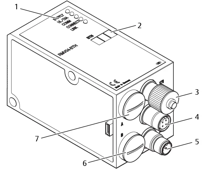 Fig. 1: Bus coupler device overview with I/O modules and valve terminal (sample configuration)
- Left end plate
- Bus coupler, type B-design
- FE connection
- Alternative FE connection using the screw from (5)
- Output module or input module
- B-design stand-alone module extension.
- Valve terminal
For the output or input modules, up to 6 modules can be connected in any com-bination (e.g. 3 input and 3 output modules).
B-design stand-alone module extension and the valve terminal have their own operating instructions.
With the B-design stand-alone module extension, up to 3 modules (module ex-tensions) can be integrated in any combination.
Device components
Bus coupler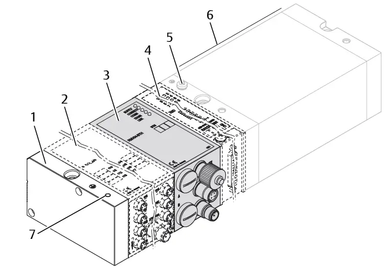 Fig. 2: Bus coupler overview
- LED displays for diagnostic messages
- Bus slave label
- X71 (optional service interface (RS232))
- X72 (BUS) connection to control valves and the I/O modules
- X10 (POWER) connection to supply voltage to the valve coils, logic and inputs Screw cap B for S4, S5, S6 sliding switches (valve assignment to supply voltage)
- Screw cap A for rotary switches S1, S2 (no function) and DIP switch S3 (no function)
The bus coupler is only intended for use as a slave in an EtherNet/IP™ bus system based on transmission standard IEEE 802.3.
The module is connected to a switch/hub via a cable that is compliant with the EtherNet/IP™ specification or directly connected to a controller.
Diagnosis
The logic and valve control supply voltage are monitored. If they exceed or fall below a set limit, an error signal will be generated and confirmed with the diag-nostic LED and the diagnostic information.
Number of valves that can be controlled
Up to 16 double or 32 single solenoid valves or a suitable combination of double and single solenoid valves can be connected. In each case, up to 32 valve coils can be controlled.
Input/output modules
Input/output modules with releasable plug connections allow electrical input and output signals to be output via the valve system’s bus connection.
Number of connectable modules
Input as well as output modules can be connected to the valve system with bus coupler in any combination not exceeding 6 modules in total. Any order may be used.
- Make sure to stay within the load limits.
The bus coupler supplies the inputs for the input modules. The maximum total current for all inputs is 0.7 A.
The output module is supplied via an M12 connection, with one power supply each for 4 outputs. See g Table 11.
Input modules
The input modules used to connect electric sensor signals are available in two versions:
- 8x M8 (RMV04-8DI_M8) or
- 4x M12, double-assigned (RMV04-8DI_M12)
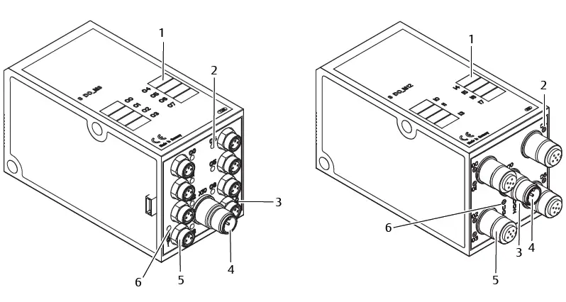
Fig. 3: 8x input module: RMV04-8DI_M8 (left) and RMV04‑8DI_M12 (right)
- Label
- RMV04-8DI_M8: 8 inputs, 8DI_M8
RMV04-8DI_M12: 4 inputs, 8DI_M12, double-assigned - LED display (yellow, state) for each input
Output modules
The output modules used to connect the actuators are available in two versions:
- 8x M8 (RMV04-8DO_M8) or
- 4 x M12, double-assigned (RMV04-8DO_M12)
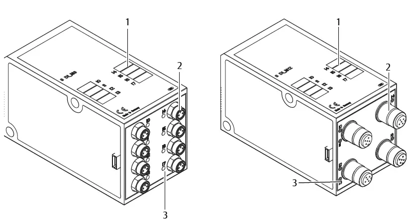
Fig. 4: 8x output module: RMV04-8DO_M8 (left) and RMV04-8DO_M12 (right)
- Label
- LED display (yellow, state) for each output
- Load supply connection via M12 plug
- Two-color LED display for load supply UQ1
- Two-color LED display for load supply UQ2
- RMV04-8DO_M8: 8 outputs,
8DO_M8 RMV04-8DO_M12:
4 out-puts, 8DO_M12, double-assigned
Assembly
Assembling the valve system with bus coupler
You will receive your individually configured valve system completely fitted with all components:
- Valve terminal
- Bus coupler
- Up to six I/O modules (if needed)
- Up to three module extensions (if needed)
The operating instructions accompanying the VS describe in full how to assemble the entire valve system. Any mounting orientation may be used with the VS. The dimensions of the complete VS vary according to module equipment.
Labeling the module
Bus coupler
- Inscribe the address provided/used for the bus coupler in the bus slave field (BTN) on the bus coupler.
Input/output modules
- Label the connections directly on the labels of the input/output modules.
The markings on the connections indicate which labels are assigned to the connections.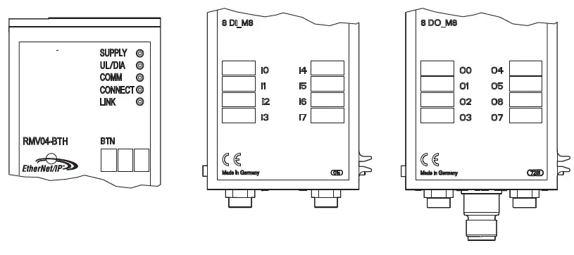
Fig. 5: Labels on the bus coupler (CMS-B-BEIP), input module (8DI_M8), and out-put module (8DO_M8), examples
Connecting the bus coupler electrically
CAUTION
Applied electric voltage
Danger of injury from electric shock
- Make sure the relevant system component is not under voltage or pressure before electrically connecting modules to the valve terminal.
NOTICE
Faulty wiring
Faulty wiring can lead to malfunctions as well as damage to the network.
- Unless otherwise stipulated, comply with the directive Network Infrastructure for EtherNet/IP™ Publication Number: PUB00035R0.
- Only a cable that meets the fieldbus specifications as well as the connection speed and length requirements should be used.
- In order to assure both the protection class and the required strain relief, the cable and plug assembly must be done professionally and in accordance with the assembly instructions.
NOTICE
Current flow in shield due to differences in potential
Compensating currents caused by differences in potential must not flow over the shield of the bus cable, as this will remove the shielding, which could dam-age the line and connected bus coupler.
- If necessary, connect the measuring points for the system using a separate line.
General notes on connecting the bus coupler
Use pre-assembled plug connections to connect the modules.
- Observe the pin assignment in the following table if you do not use pre-assembled plug connections and cables.

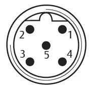
Table 3: X71 pin assignment (RS232), M12, 5-pin
| Pin | Signal | Meaning |
| 1 | nc | Not Connected |
| 2 | nc | Not Connected |
| 3 | RXD | Received data |
| 4 | GND | Reference potential to 0 V |
| 5 | TXD | Transmission data |
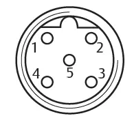 Table 4: X72 pin assignment (BUS), M12, D-coded
| Pin | Signal | Meaning |
| 1 | TD+ | Transmit pos. |
| 2 | RD+ | Receive pos. |
| 3 | TD- | Transmit neg. |
| 4 | RD- | Receive neg. |
| 1 | TD+ | Transmit pos. |
The connection technology and plug assignment comply with the specifications in the technical guidelines Network Infrastructure for EtherNet/IP™ Publication Number: PUB00035R0.
Connecting the bus coupler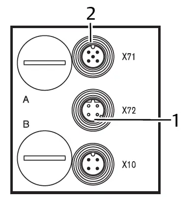
- 1 X72 bus cable
- 2 X71 plug
- Set up the correct pin assignment on the plug connections if you do not use pre-assembled cables. See g Table 4.
- Connect the incoming bus connection to X72 (1) and connect the module with a hub or switch if further participants are to be connected.
- Provide the X71 plug (2) with a cover cap.
- Connect the shield on both sides of the bus cable directly to the plug housing (EMC housing) if self-assembled cables and plugs with metal housing are used.
This protects data lines from terminal interference. - Ensure that the plug housing is securely fitted to the bus coupler housing.
Connecting the bus coupler logic and load supply
Operating voltage is supplied to the valves and the bus coupler via the X10 (POWER) plug.
When connecting the logic and load supply of the bus coupler, ensure pin assignment according to the following table.
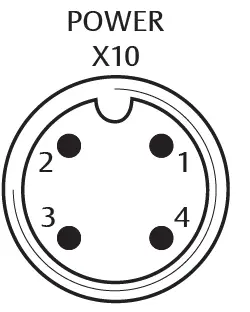 Fig. 6: X10 plug (Power)
Table 5: Assignment of the X10 (POWER) plug, M12, A-coded
| Pin | X10 | Assignment |
| 1 | UL | Power supply for bus coupler logic and sensor supply for digital in- put modules |
| 2 | UQ1 | First valve power supply |
| 3 | OV | Ground for UL, UQ1 and UQ2 |
| 4 | UQ2 | Second valve power supply |
- UL, UQ1 and UQ2 are galvanically connected to one another.
- Groups of valves can be supplied with power via the UQ1 and UQ2 valve sup-plies.
- The S4, S5, and S6 sliding switches are used to assign the valve groups (4 or 8 valves). See section g 7.1.1. Assigning the valve supply. It is therefore possi-ble to switch off the valves before or after an emergency OFF.
The power supply cable must fulfill the following requirements:
- Cable socket: 4-pin, A-coded without center hole
- Cable cross section: > 0.5 mm2 per wire
- Length: Max. 20 m
Table 6: Current consumption on X10 (POWER) on bus coupler
| Signal | Assignment | Total current |
| UL | Logic supply and input | Max. 1 A |
| UQ1 | Valves | Max. 1 A |
| UQ2 | Valves | Max. 1 A |
A standard power pack can supply all system components with 24 V.
CAUTION
Dangerous voltages
A power pack without safe isolation may lead to dangerous voltages in the event of a malfunction. Injuries from electric shock and system damage may be the consequences.
- Only use a power pack with safe isolation according to EN60747, VDE 0551 classification! The corresponding electrical circuits are thus SELV/PELV cir-cuits in accordance with IEC 60364-4-41.
To connect the bus coupler load supply:
- Set up the correct pin assignment on the plug connections if you do not use pre-assembled cables. See g Table 5.
- Connect the bus coupler operating voltages using the electrical connector. See section g 11. Spare parts and accessories.
- Check the operating voltage specifications using the electrical characteristics and comply with them. See section g 10. Technical data.
- Provide power according to g Table 6. Select the cable cross-section accord-ing to the cable length and occurring currents.
Connecting the 8x input/output modules
CAUTION
Freely accessible conductive parts
Risk of electric shock on contact!
- When connecting peripheral devices (I/O interface), observe the requirements to protect against accidental contact in accordance with EN 50178, classification VDE 0160.
Input module
- Wire the inputs (DI8_M8) or (DI8_M12). See g Table 10 and g Table 9.
- Connect the electrical inputs/outputs to the I/O modules with M8 or M12 coupling plugs (accessories).
- To ensure the IP65 protection class, close unused sockets with M8 or M12 protective caps (accessories).
The total current for all sensor supplies (pin 1) on one valve system must not exceed 0.7 A.
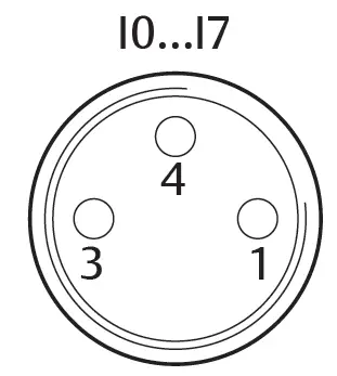 Table 7: Pin assignment for 8x input module, DI8_M8, M8x1 socket
| Pin | Signal | Assignment |
| 1 | SENSOR+ | Sensor supply + |
| 3 | SENSOR– | Reference potential |
| 4 | I0 to I7 | Sensor’s signal |
| Housing | Connected to shield potential |
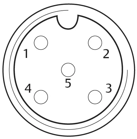 Table 8: Pin assignment for 8x input module, DI8_M12, M12x1 socket
| Pin | Signal | Assignment |
| 1 | SENSOR + | 24 V sensor supply |
| 2 | I1, I3, I5 or I7 | Sensor’s signal |
| 3 | SENSOR – | GND reference potential |
| 4 | I0, I2, I4 or I6 | Sensor’s signal |
| 5 | NC | not assigned |
| Housing | Connected to shield potential |
Output module
- Wire the outputs (DO8_M8) or (DO8_M12). See g Table 8 and g Table 7.
- Connect the electrical inputs/outputs to the I/O modules with M8 or M12 coupling plugs (accessories).
- To ensure the IP65 protection class, close unused sockets with M8 or M12 protective caps (accessories).
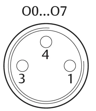 Table 9: Pin assignment for 8x output module, DO8_M8, M8x1 socket
| Pin | Signal | Assignment |
| 1 | Free | not assigned |
| 4 | Ox | Ox output signal (Nominal voltage 24 V) |
| 3 | GND | GND actuator reference |
| Housing | Connected to shield potential |
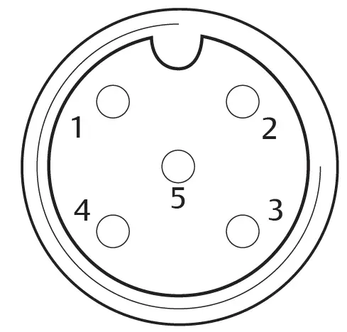 Table 10: Pin assignment for 8x output module, DO8_M12, M12x1 socket
| Pin | Signal | Assignment |
| 1 | NC | not assigned |
| 2 | O1, O3, O5 or O7 | Output signal |
| 3 | GND | Reference potential |
| 4 | O0, O2, O4 or O6 | Output signal |
| 5 | NC | not assigned |
| Housing | Connected to shield potential |
NOTICE
Total current is too high
Every output is supplied with a continuous current of max. 0.5 A. Current loads over 0.5 A per output can damage the system.
- Make sure that the current load of 0.5 A per output is not exceeded.
Connecting the output module load supply
Each output module has its own M12 connection for the load supply. Each of the 4 outputs are supplied via the load supply. The UQ1 and UQ2 voltages are galvanically isolated.
The connection cable for the output module load supply must meet the following requirements:
- Cable socket: M12x1, 4-pin, A-coded without center hole (to ensure correct plug-in connection)
- Cable cross section: > 0.5 mm2 per wire
- Length: Max. 20 m
- Set up the correct pin assignment on the plug connections if you do not use pre-assembled cables.
- Connect the load supply using the M12 plug.
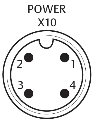 Fig. 7: Plug assignment X10 (POWER)
Table 11: Load supply assignment for 8x output module, DO8, M12x1, A-coded
| Pin | X10 | Assignment |
| 1 | 0V_UQ2 | GND reference for supply voltage 2 |
| 2 | 24V_UQ1 | 24 V supply voltage 1 for outputs O0 to O3 |
| 3 | 0V_UQ1 | GND reference for supply voltage 1 |
| 4 | 24V_UQ2 | 24 V supply voltage 2 for outputs O4 to O7 |
FE connection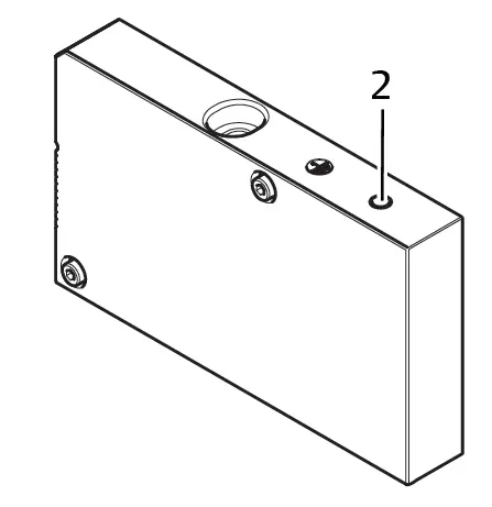 Fig. 8: FE connection
2 FE connection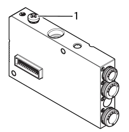 Fig. 9: FE connection, HF04/HF04XF
1 FE connection
- To discharge EMC interferences, connect the FE connection (2) on the left end plate to the functional grounding via a low-impedance line. See g Fig. 8. Recommended cable cross-section: 10 mm2.
CAUTION
For module extensions (optional): insufficient grounding
If module extensions are used, grounding on the FE connection (2) is insufficient due to the plastic housing for the module extension. - If using module extensions, also connect the FE connection for each mod-ule extension to the functional grounding via a low-impedance line.
See also
FE connection [} 24]
Commissioning and operation
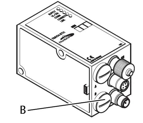 Fig. 10: Assigning the valve supply
B PG connector
Making presetting’s
The following presetting’s have to be made:
- Assigning the valve supply
Assigning the valve supply
The S4, S5, and S6 switches for assigning the valve supply are located beneath PG fitting (B). The following is assigned to each switch:
- 4 double subbases for double solenoid valves (with solenoids 12 and 14) or
- 8 double subbases for single solenoid valves (with solenoid 14).
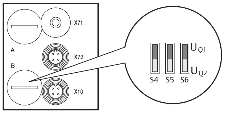 Fig. 11: S4, S5, S6 switches for assigning valve supply voltages (UQ1, UQ2)
This switch allows valves to be assigned in groups to valve supply voltages UQ1 and UQ2.
When delivered, all valves are assigned to the UQ1 voltage.
Table 12: Assignment of the S4, S5, and S6 switches
| Switch | Byte | Double subbases for double solenoid valves (solenoids 12, 14) | Double subbases for single solenoid valves (solenoid 14) |
| S4 | 0 | 1 – 4 | 1 – 8 |
| S5 | 1 | 5 – 8 | 9 – 16 |
| S6 | 2, 3 | 09 – 16 | 017 – 32 |
NOTICE
Voltage at switches
Switches can be damaged if voltage is applied to them during operation.
- Always operate switches in a voltage-free state!
How to assign the valve supply:
See g Fig. 11:
- Open the lower screw cap (B).
- Using the S4, S5, and S6 switches, assign each valve group to one of the two supply voltages UQ1 or UQ2. See also g Table 12.
Below you will find examples for the assignment of the S4, S5, and S6 switches and for supplying assembled valves. The following example combinations are listed there:
| Examples4) | Double subbases used5)6) | Valve equipment |
| Example 1 | Double subbases for double solenoid valves | Double solenoid valves |
| Example 2 | Double subbases for double solenoid valves | Single solenoid valves |
| Example 3 | Double subbases for double solenoid valves | Single and double solenoid valves |
| Example 4 | Double subbases for single solenoid valves | Single solenoid valves |
| Example 5 | Double subbases for double solenoid valves | Double solenoid valves |
| Combined with | ||
| Double subbases for single solenoid valves | Single solenoid valves |
| Examples4) | Double subbases used5)6) | Valve equipment |
| Example 6 | Double subbases for double solenoid valves | Single and double solenoid valves |
| Combined with | ||
| Double subbases for single solenoid valves | Single solenoid valves |
- These examples only apply if there are no module extensions. You can also arrange other combinations based on your requirements.
- From an electrical connection viewpoint, the double subbases for double solenoid valves must come first and then those for single solenoid valves.
- The maximum number of solenoids for all subbases is 32.
Table 13: Examples for assignment of switches and valve supply
| Example 1 | Example 2 | Example 3 | ||||||
| Swi tch | Byt e | Ad- dress | Double subbase for double solenoid valves | |||||
| Valve po- sition7) | Sol. LED | Valve po- sition8) | Sol. LED | Valve po- sition8) | Sol. LED | |||
| S4 | 0 | A0.0 | 1 | 14 | 1 | 14 | 1 | 14 |
| A0.1 | 12 | – | 12 | |||||
| A0.2 | 2 | 14 | 2 | 14 | 2 | 14 | ||
| A0.3 | 12 | – | 12 | |||||
| A0.4 | 3 | 14 | 3 | 14 | 3 | 14 | ||
| A0.5 | 12 | – | 12 | |||||
| A0.6 | 4 | 14 | 4 | 14 | 4 | 14 | ||
| A0.7 | 12 | – | 12 | |||||
| S5 | 1 | A1.0 | 5 | 14 | 5 | 14 | 5 | 14 |
| A1.1 | 12 | – | 12 | |||||
| A1.2 | 6 | 14 | 6 | 14 | 6 | 14 | ||
| A1.3 | 12 | – | – | |||||
| A1.4 | 7 | 14 | 7 | 14 | 7 | 14 | ||
| A1.5 | 12 | – | – | |||||
| A1.6 | 8 | 14 | 8 | 14 | 8 | 14 | ||
| A1.7 | 12 | – | – | |||||
| S6 | 2 | A2.0 | 9 | 14 | 9 | 14 | 9 | 14 |
| A2.1 | 12 | – | – | |||||
| A2.2 | 10 | 14 | 10 | 14 | 10 | 14 | ||
| A2.3 | 12 | – | 12 | |||||
| A2.4 | 11 | 14 | 11 | 14 | 11 | 14 | ||
| A2.5 | 12 | – | 12 | |||||
| A2.6 | 12 | 14 | 12 | 14 | 12 | 14 | ||
| A2.7 | 12 | – | – | |||||
| S6 | 3 | A3.0 | 13 | 14 | 13 | 14 | 9 | 14 |
| A3.1 | 12 | – | – | |||||
| A3.2 | 14 | 14 | 14 | 14 | 10 | 14 | ||
| A3.3 | 12 | – | 12 | |||||
| A3.4 | 15 | 14 | 15 | 14 | 11 | 14 | ||
| A3.5 | 12 | – | 12 | |||||
| A3.6 | 16 | 14 | 16 | 14 | 12 | 14 | ||
| A3.7 | 12 | – | – | |||||
Table 14: Examples for assignment of switches and valve supply
| Example 4 | Example 5 | Example 6 | ||||||
| Swi tch | Byte | Ad- dress | Double subbase for single solenoid valves | double subbase for single and double solenoid valves | ||||
| Valve posi- tion7) | Sol. LED | Valve po- sition8) | Sol. LED | Valve po- sition8) | Sol. LED | |||
| S4 | 0 | A0.0 | 1 | 14 | 1 | 14 | 1 | 14 |
| A0.1 | 2 | 14 | 12 | 12 | ||||
| A0.2 | 3 | 14 | 2 | 14 | 2 | 14 | ||
| A0.3 | 4 | 14 | 12 | – | ||||
| A0.4 | 5 | 14 | 3 | 14 | 3 | 14 | ||
| A0.5 | 6 | 14 | 12 | – | ||||
| A0.6 | 7 | 14 | 4 | 14 | 4 | 14 | ||
| A0.7 | 8 | 14 | 12 | 12 | ||||
| S5 | 1 | A1.0 | 9 | 14 | 5 | 14 | 5 | 14 |
| A1.1 | 10 | 14 | 6 | 14 | 12 | |||
| Example 4 | Example 5 | Example 6 | ||||||
| Swi tch | Byte | Ad- dress | Double subbase for single solenoid valves | double subbase for single and double solenoid valves | ||||
| Valve posi- tion7) | Sol. LED | Valve po- sition8) | Sol. LED | Valve po- sition8) | Sol. LED | |||
| A1.2 | 11 | 14 | 7 | 14 | 6 | 14 | ||
| A1.3 | 12 | 14 | 8 | 14 | 12 | |||
| A1.4 | 13 | 14 | 9 | 14 | 7 | 14 | ||
| A1.5 | 14 | 14 | 10 | 14 | 8 | 14 | ||
| A1.6 | 15 | 14 | 11 | 14 | 9 | 14 | ||
| A1.7 | 16 | 14 | 12 | 14 | 10 | 14 | ||
| S6 | 2 | A2.0 | 17 | 14 | 13 | 14 | 11 | 14 |
| A2.1 | 18 | 14 | 14 | 14 | 12 | 14 | ||
| A2.2 | 19 | 14 | 15 | 14 | 13 | 14 | ||
| A2.3 | 20 | 14 | 16 | 14 | 14 | 14 | ||
| A2.4 | 21 | 14 | 17 | 14 | 15 | 14 | ||
| A2.5 | 22 | 14 | 18 | 14 | 16 | 14 | ||
| A2.6 | 23 | 14 | 19 | 14 | 17 | 14 | ||
| A2.7 | 24 | 14 | 20 | 14 | 18 | 14 | ||
| S6 | 3 | A3.0 | 25 | 14 | 21 | 14 | 19 | 14 |
| A3.1 | 26 | 14 | 22 | 14 | 20 | 14 | ||
| A3.2 | 27 | 14 | 23 | 14 | 21 | 14 | ||
| A3.3 | 28 | 14 | 24 | 14 | 22 | 14 | ||
| A3.4 | 29 | 14 | 25 | 14 | 23 | 14 | ||
| A3.5 | 30 | 14 | 26 | 14 | 24 | 14 | ||
| A3.6 | 31 | 14 | 27 | 14 | 25 | 14 | ||
| A3.7 | 32 | 14 | 28 | 14 | 26 | 14 | ||
- White fields indicate valve positions with double solenoid valves.
- Fields with numbers marked in bold indicate valve positions with single solenoid valves.
Configuring the bus coupler
The description in this section refers to the software BOOTP/DHCP Server, Version 2.3.2.0 of Rockwell Automation Inc. The software also contains online documentation which has to be observed during operation.
The configuration steps laid out in this section are superior to the settings on the bus coupler which have already been described and are a part of the entire system’s bus master configuration. See section g 7.1. Making presetting’s.
The work described here may only be carried out by qualified electronics personnel and in compliance with the operator’s documentation on configuring the bus master, as well as applicable technical standards, directives, and safety regulations.
Before starting configuration, the following steps must have been carried out and completed on the bus coupler:
- You have assembled the bus coupler and the valve terminal. See section g 6. Assembly.
- You have connected the bus coupler.
See section g 6.3. Connecting the bus coupler electrically. - You have carried out the presetting’s.
See section g 7.1. Making presetting’s.
The configuration may also be carried out using other configuration software, but the described parameters and settings must be adhered to.
Configuring the bus system
EtherNet/IP™ stands for “Ethernet Industrial Protocol”. It is an open bus system that is based on the IEEE 802.3 standard and supports the widely used family of TCP/IP protocols. This is why it is also subject to specifications and limitations when assigning IP addresses (RFC: 791 INTERNET PROTOCOL; DARPA INTERNET PROGRAM PROTOCOL SPECIFICATION September 1981). To avoid the problems of a factory-set static IP address, the bus unit is set by default to address assignment using the DHCP protocol.
A dynamic or static IP address can then be assigned using the appropriate tool.
Before you start to configure the bus system, consult your network administrator on how to configure the network. Ask for the values for the subnet mask, gate-way, primary DNS, secondary DNS, and domain name.
To configure the bus system:
- Start the BOOTP/DHCP server program.
When the program is started for the first time, the network settings must be adjusted (steps 2 to 4). - In the menu bar, click “Tools” > “Network Settings”.
- Enter the values for “subnet mask”, “gateway”, “primary DNS”, “secondary DNS” and “domain name”.
- Click “OK”.
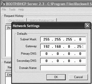 Fig. 12: BOOTP/DHCP server, network settings dialog
The bus coupler sends a DHCP query with its individual hardware address (MAC address). A line appears in the “Request History” window. Example: “13:57:39 DHCP 00:04:F3:00:1C:40”
- Right click on this line.
- Click “Add to Relation List”.
The “New Entry” window opens. - Enter the IP address and confirm with “OK”.
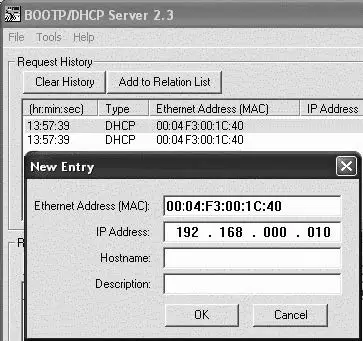 Fig. 13: BOOTP/DHCP server, new entry dialog
The IP address is taken over in the relation list and transferred during the next query to the respective module. A line appears in the “Request History” window. Example: “14:00:32 DHCP 00:04:F3:00:1C:40 192.168.0.10”.
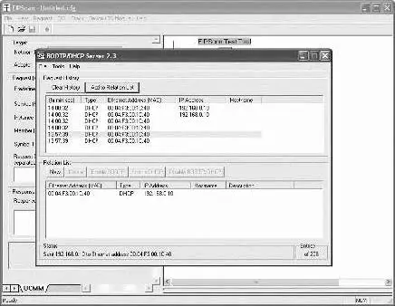 Fig. 14: BOOTP/DHCP server, relation list dialog
Saving the address list
You can save the list with “File” > “Save As” so you do not have to manually assign an IP address to each participant after every program start.
You can load the list with “File” > “Open“ after the next program start.
Change the IP address.
The specified IP address can be changed at any time:
- Right click on the module in the relation list.
- Click “Properties”.
- Enter a new IP address and click “OK”.
The new IP address will be taken over after the next power reset.
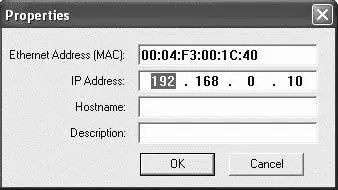 Fig. 15: BOOTP/DHCP server, properties dialog
Dynamic or static IP address
You can change the currently assigned IP address to a static IP address by clicking the “Disable BOOTP/DHCP” button. A BOOTP/DHCP server will no longer be needed for this device during the next system start.
If the module is entered in the relation list and highlighted with a right click, you can reactivate the automatic address assignment by clicking the “Enable DHCP” button.
EIP
Configuring the fieldbus module
To be able to address the module from a controller, the module must first be con-figured.
In the following example, configuration of a Logix5000 is explained.
- Start the program RSLogix5000 and the current project.
“Offline” must be selected in the menu as the connection status. - Expand the “I/O Configuration” folder in the tree structure and right-click the “Ethernet” branch.
- Select “New Module”.
- Click “Ethernet-Module – Generic Ethernet Module” and confirm with “OK”.
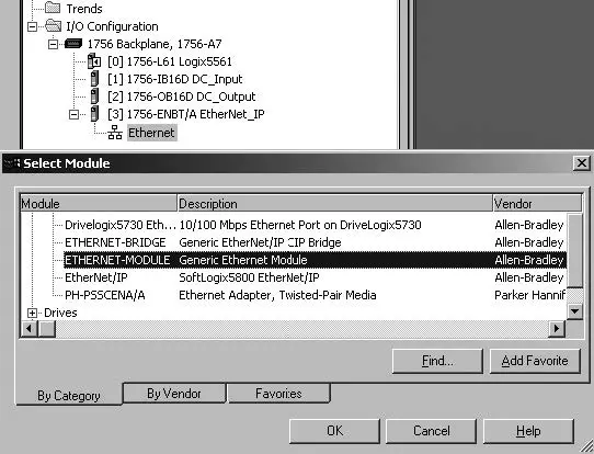 Fig. 16: Select Module dialog
- In the “General” tab, enter the corresponding values in the fields.
| Parameter | Value |
| Name: | As per project |
| Comma format: | “Data – SINT” |
| IP Address: | As per project |
| Input: | |
| Assembly Instance: | 102 |
| Size: | 11 (8-bit) |
| Output: | |
| Assembly Instance: | 100 |
| Size: | 10 (8-bit) |
| Configuration: | |
| Assembly Instance: | 1 |
| Size: | 0 (8-bit) |
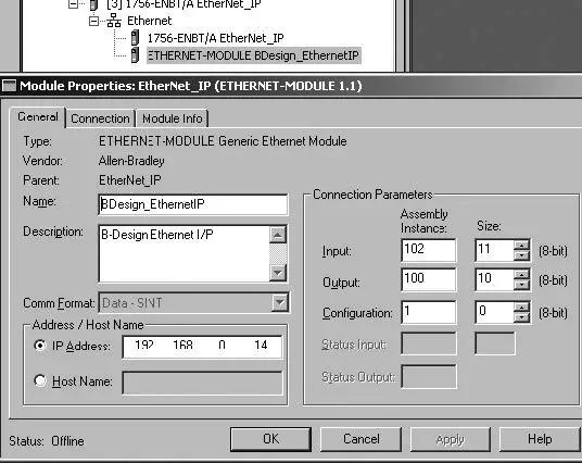 Fig. 17: Select Module dialog
- Click the “Connection” tab.
- In the “Requested Packet Interval (RPI)” field, enter a value ≥ 10 ms and con-firm with “OK”.
The configured device appears under the “Ethernet” branch in the tree structure.
You can check the configuration by selecting the connection status “Go Online”. Any configuration errors are indicated by means of a yellow exclamation point in the tree structure.
Configuring inputs and outputs
The inputs and outputs can be configured as shown in the following example.
- In the program RSLogix5000, double click the branch “Controller Tags” under “Controller Logix5561” in the tree structure.
Different menu groups appear in the right area of the window. The menu group with the name stored in the configuration (in the example “BDesign”) represents the valve unit B-Design Ethernet/IP. - Expand the menu group “B Design:O” by clicking the “+” symbol.
- Expand the menu group “BDesign:O Data” by clicking the “+” symbol.
The following window appears:
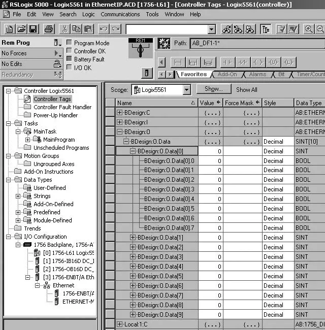 Fig. 18: Controller Tags dialog
As soon as you expand the listed bytes (e.g. “BDesign:O.Data[0]”) by clicking the “+” symbol, the corresponding bits are displayed.
You can view input and diagnostic data by expanding the menu group “BDe-sign:I”.
Example:
Table 15: B Design: I. Data[6] (Module Diagnostics)
| Bit | Function |
| 0 | none <value = 0> |
| 1 | none <value = 0> |
| 2 | Supply voltage for outputs 1-8 |
| 3 | Supply voltage for outputs 9-16 |
| 4 | Supply voltage for outputs 17-32 |
| 5 | Electrical supply voltage for external modules |
| 6 | none <value = 0> |
| 7 | none <value = 0> |
Testing and diagnosis on the modules
Reading the diagnostic display on the bus coupler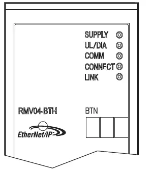
The LEDs on the bus coupler’s front plate report the messages listed in the following table.
- Before commissioning and during operation, regularly check bus coupler functions by reading the diagnostic displays.
| LED | Signal | Description |
| Supply (UQ1/UQ2) | Green | Logic supply available Valve supply UQ1/UQ2 OK |
| Red | Valve or sensor supply overload (Group diagnosis) Under voltage (UQ1/UQ2 < 18.5 V) | |
| UL | Green | Logic voltage available |
| Off | No logic voltage available (UL < 16 V) | |
| Diagnosis | Green | No diagnostic message |
| Red | Diagnostic message present | |
| COMM | No function | |
| Connected | Green | “Unconnected!” or “Class1/3 connection” established For Class 1/3 connection: PLC in RUN mode |
| Red | For Class 1/3 connection: PLC in STOP | |
| Link | Physical Ethernet link established |
Check sensors on the input module
There is one LED per input on the input module for monitoring purposes. The LED lights up if the signal level is high.
- Before commissioning the system, check the sensor function and method of operation by reading the LEDs.

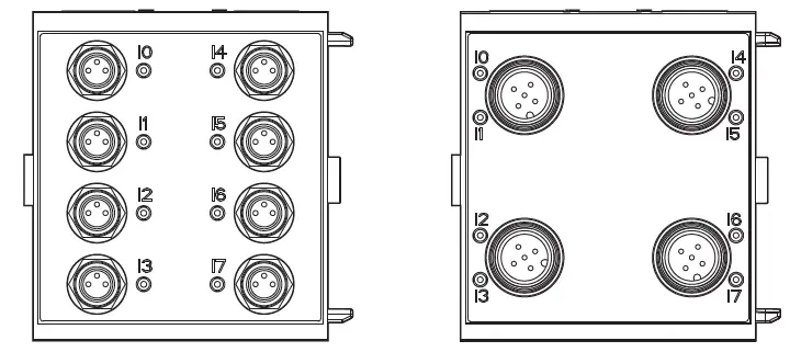
Fig. 19: LED displays on the M8 input module (left) and M12 (right)
| LED | Color | Meaning |
| Input | Yellow | High signal level mode |
Check actuators on the output module
- Before commissioning, check the actuator function and the method of operation using the LED displays on the output module.

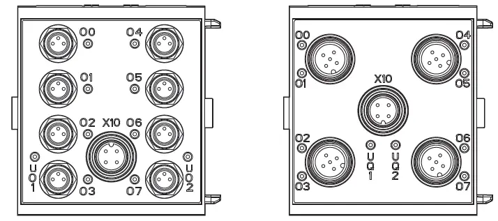
Fig. 20: LED displays on the M8 output module (left) and M12 (right)
Table 16: Meaning of the LED displays on the output module
| LED | Color | Meaning |
| UQ1 | Green | Load supply UQ1 available |
| Red | Diagnosis: Overload/short circuit of controlled output O0, O1, O2, or O3 | |
| Off | Load supply UQ1 not available (e.g. emergency OFF) | |
| UQ2 | Green | Load supply UQ2 available |
| Red | Diagnosis: Overload/short circuit of controlled output O4, O5, O6, or O7 | |
| Off | Load supply UQ2 not available (e.g. emergency OFF) | |
| O0 … O7 | Off | Corresponding LOW level output |
| Yellow | Corresponding HIGH level output |
Commissioning the bus coupler
Before commissioning the system, the following steps must have been carried out and completed:
- You have assembled the valve terminal and the bus coupler.
See section g 6.1. Assembling the valve system with bus coupler. - You have connected the bus coupler.
See section g 6.3. Connecting the bus coupler electrically. - You have carried out the presetting’s and configuration.
See section g 7.1. Making presetting’s and g 7.2. Configuring the bus coupler. - You have configured the bus master so that it controls the valves and the in-put module correctly.
- You have carried out the diagnostic test on the input/output modules. See section g 7.4. Testing and diagnosis on the modules.
Commissioning and operation may only be carried out by qualified electrical or pneumatic personnel or an instructed person under the direction and supervision of qualified personnel. See section g 2.4. Personnel qualifications.
CAUTION
Risk of uncontrolled actuator movements when the pneumatics are switched on
Danger of injury if the system is in an undefined state and the manual overrides are not set to position “0”.
- Put the system in a defined state before switching it on.
- Set all manual overrides to position “0”.
- Make sure that no personnel are within the hazardous zone when the pressure is switched on.
- Also observe the applicable instructions and safety information in the VS operating instructions.
- Switch on the operating voltage.
- Check the LED displays on all modules.
- Switch on the compressed air supply.
Disassembly and exchange
You can either exchange the bus coupler or connect additional input/output modules and module extensions as needed.
The AVENTICS warranty only applies to the delivered configuration and extensions taken into account in the configuration. The warranty no longer applies after a conversion that exceeds these extensions.
Exchange the bus coupler
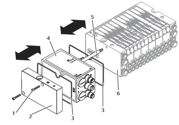
Fig. 21: Exchanging the bus coupler, example
- Hexagonal socket-head screws
- Left end plate
- Seal
- Bus coupler
- Tie rod
- Left end plate with connections
CAUTION
Applied electric voltage and high pressure!
Danger of injury from electric shocks and sudden pressure drops.
- Make sure the system is not under pressure or voltage before you exchange the modules.
- Disconnect the electrical connections from the bus coupler (4).
- Unscrew the end plate (2) and (if applicable) all input/output modules to the left of the bus coupler (each with 2 DIN 912 – M4 hexagonal socket-head
screws (1), wrench size 3) and remove from the tie rods (5). - Remove bus coupler (4) from the tie rods (5).
- Push the new bus coupler (4) onto the tie rods (5).
- Make sure that
- The tie rods (5) have been completely screwed in and
- The seals (3) have been inserted correctly.
- Push the input/output modules (if applicable) in the original order and then the left end plate (2) onto the tie rods (5) and screw into place (each with 2
DIN 912 – M4 hexagonal socket-head screws (1), wrench size 3).
Tightening torque: 2.5 … 3.0 Nm. - Make all the presettings on the new bus coupler (4). See section g 7.1. Making presettings.
- Reestablish the connections.
- Check the configuration and adjust if necessary. See section g 7.2. Configuring the bus coupler.
Mounting input/output module(s)
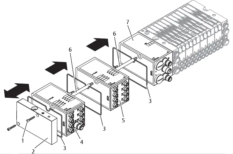 Fig. 22: Mounting input/output module(s), example
- Hexagonal socket-head screws
- Left end plate
- Seal
- Output module
- Input module
- Tie rod
CAUTION
Applied electric voltage and high pressure!
Danger of injury from electric shocks and sudden pressure drops. u Make sure the system is not under pressure or voltage before you exchange the modules.
A maximum of 6 modules (input or output) may be mounted on one valve system. Observe the permissible current load!
- Unscrew the left end plate (2) from the bus coupler (7) or from the last input (5) or output module (4) of the valve system (2 DIN 912 M4 hexagonal socket-head screws (1), wrench size 3) and remove it from the tie rods (6).
- Screw the tie rods (6) for the input (5) or output modules (4) on the existing tie rods (6) (2 per input (5) or output module (4)). – Ensure that the tie rods (6) are flush with the surface!
- Attach the (additional) input (5) or output module (4) to the tie rods (6). – Make sure the seals (3) have been correctly inserted and that the contacts have been properly connected.
- Retighten the left end plate (2) after the last input (5) or output module (4) (2 hexagonal head-socket screws DIN 912 M4 (1), wrench size 3). Tightening torque: 2.5 to 3 Nm.
- Establish the connections. See section g 6.3.3. Connecting the bus coupler logic and load supply.
CAUTION
Open inputs/outputs
Danger of electric shocks caused by contact, short circuits, or damage to the system.
- Always close unused inputs or outputs with protective caps to comply with the IP65 protection class. See section g 11. Spare parts and accessories.
Adjust the configuration. See section g 7.2. Configuring the bus coupler.
Care and maintenance
CAUTION
Applied electric voltage and high pressure!
Danger of injury from electric shocks and sudden pressure drops.
- Make sure the system is not pressurized or connected to power before carrying out any service or maintenance work.
Servicing the modules
NOTICE
Damage to the housing surface caused by solvents and aggressive deter-gents!
The surfaces and seals could be damaged by solvents or aggressive cleaning agents.
- Never use solvents or aggressive detergents!
- Regularly clean the device with a damp cloth. Only use water or a mild cleaning agent
Maintaining the modules
The bus coupler and I/O modules for the VS are maintenance-free.
- Comply with the maintenance intervals and specifications for the entire system.
Technical data
Characteristics
| General | |
| Degree of protection according to EN 60 529/IEC 529 | IP 65 when assembled |
| Ambient temperature ϑU | 0°C to +50°C, without condensation |
| Electromagnetic compatibility | |
| Interference emission | EN 61000-6-4 |
| Interference immunity | EN 61000-6-2 |
Bus coupler
| Electrics | |
| Logic operating voltage UL | 24 V DC (+20 %/–15 %) |
| Operating voltage load UQ1/UQ2 | 24 V DC (±10 %) Protective extra-low voltage (SELV/PELV) according to EC 364-4-41, Residual ripple 0.5 % |
8x input modules, RMV04-8DI_M8 and RMV04-8DI_M12
| Electrics | |
| Inputs DIN EN 61131-2 | 8 digital inputs, type 3 Two-wire proximity switch with a quiescent current of max. 2.5 mA can be connected |
| Total current of 24 V sensor supply for all input modules limited to 0.7 A. | |
| Input delay 0 – 1 | 3 ms |
| Input delay 1 – 0 | 3 ms |
8x output modules, RMV04-8DO_M8 and RMV04-8DO_M12
| Electrics | |
| Outputs DIN EN 61131-2 | 8 digital outputs |
| Output voltage | Nominal value 24 V H signal voltage drop ≤ 1.5 V |
| Output current | Nominal value 0.5 A For thermal reasons, the outputs may not be loaded with anything above the nominal current for long periods. |
| Overload protection | Switches off at 0.6 to 1.2 A Autom. start-up when load is reduced |
| Line length for M8 and M12 connection | Max. 30 m |
| Power supply UQ1 and UQ2 | Nominal value 24 V (+20 %/-15 %) |
Spare parts and accessories
| Spare part | Order number |
| Bus coupler with fieldbus protocol EtherNet/ IP™ (incl. 2x tie rods,1x seal and 1x manual) | R412012755 |
| Accessories | Order number |
| M12x1 protective cap | R419800769 |
| End plate for bus coupler (incl. 2x mounting screws and 1x seal) | R412003490 |
8x input/output module, 8DI/8DO
| Order code | Order number | |
| 8x input module (8x M8) | 8DI_M8 | R412003489 |
| 8x input module (4x M12) | 8DI_M12 | R412008040 |
| 8x output module (8x M8) | 8DO_M8 | R412005968 |
| 8x output module (4x M12) | 8DO_M12 | R412005968 |
| Accessories | Cable Length | Order number |
| Straight plug connector, with self-clinching screw, M8x1, 3-pin | 2m | 894 620 360 2 |
| 5m | 894 620 361 2 | |
| 10m | 894 620 362 2 | |
| M8x1 protective cap for inputs (delivery unit = 25 pieces) | R412003493 | |
| M12x1 protective cap for inputs (delivery unit = 25 pieces) | 182 331 200 1 | |
| M12 Y-distributor with M12 self-clinching screw, 5-pin, 2x M12 cable socket, 1x M12 cable plug | 894 100 239 2 | |
Power plug for bus coupler and output module
| Order number | ||
| Plug connector for power supply, Socket, M12x1, 4-pin for cable Ø 4-8 mm, A-coded | 180o (X10, POWER) | 894 105 432 4 |
| 90o (X10, POWER) | 894 105 442 4 | |
| Plug connector for input/output modules | M12x1 plug, straight | 1 834 484 222 |
| M12x1 plug, angled | 1 834 484 223 | |
| M12x1 dual plug for cable Ø 3 mm or 5 mm | 1 834 484 246 |
Disposal
Dispose of the device in accordance with the currently applicable regulations in your country.


