![]() 3.8L – Intake Manifold — Lower – in Vehicle Repair
3.8L – Intake Manifold — Lower – in Vehicle Repair
Engine 3.8L Intake Manifold Lower in Vehicle Repair
Applies to:
3.8L
| SECTION 303-01A: Engine — 3.8L | 2000 Mustang Workshop Manual |
| IN-VEHICLE REPAIR | Procedure revision date: 06/17/1999 |
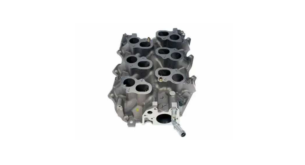
Intake Manifold — Lower
Removal
- Remove the upper intake manifold (9424). For additional information, refer to Intake Manifold — Upper in this section.
- Partially drain the cooling system. For additional information, refer to Section 303-03.
- Relieve the fuel system pressure. For additional information, refer to Section 310-00.
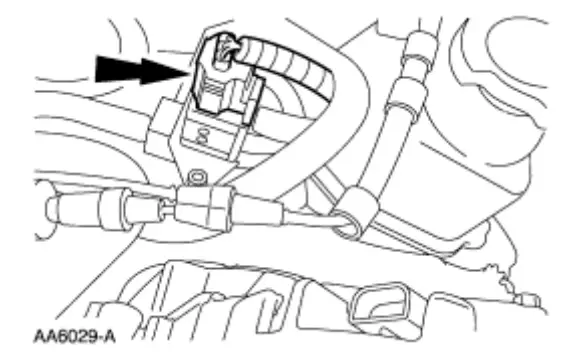
- Disconnect the fuel pressure sensor electrical connector.

- Disconnect the fuel injection supply manifold (9F792). For additional information, refer to Section 310-00.
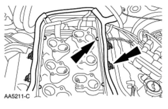
- Disconnect and position the engine wire harness (9F797) aside.

- Disconnect the heater hose (12270).

- Position the spark plug wire loom aside.

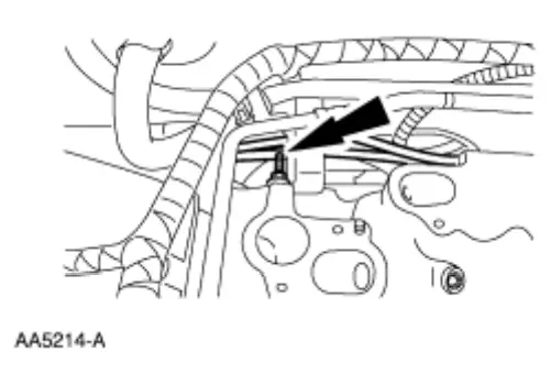
- Remove the stud bolt.

- Disconnect the exhaust gas recirculation (EGR) vacuum tube.

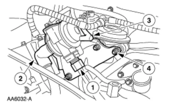
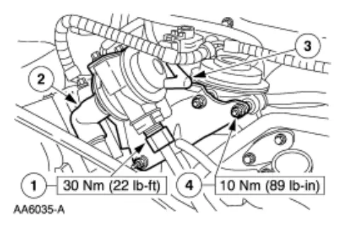
- If equipped, remove the exhaust air supply valve assembly.
1. Loosen the tube nut.
2. Disconnect the air tube.
3. Disconnect the vacuum tube.
4. Remove the nuts.
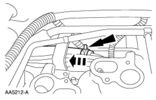
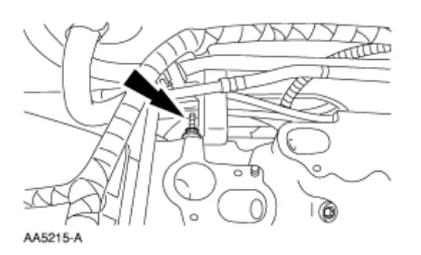
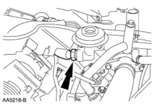
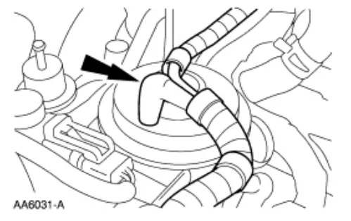
- Disconnect the EGR tube (9D477).

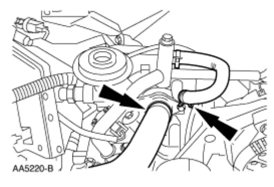
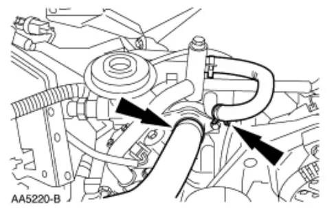
- Disconnect the coolant hoses.
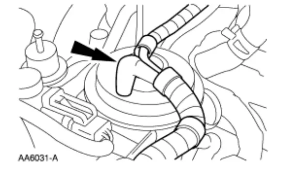
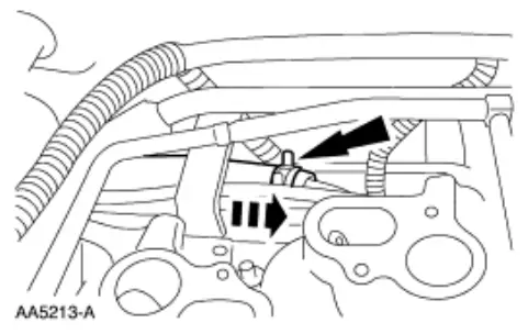
• Disconnect the upper radiator hose (8260).
• Disconnect the water bypass hose (8548).
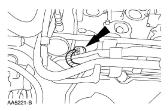
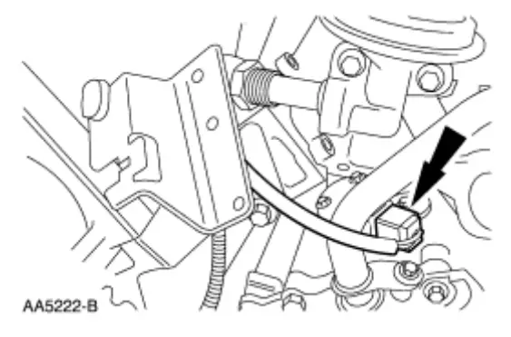
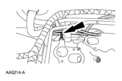
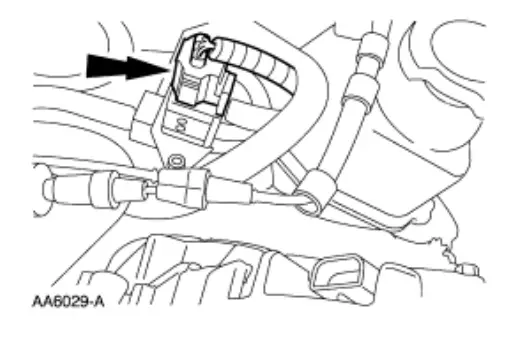
- Disconnect the electrical connector.

- Disconnect the electrical connector.

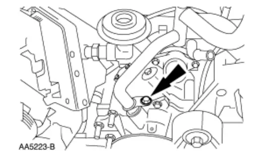
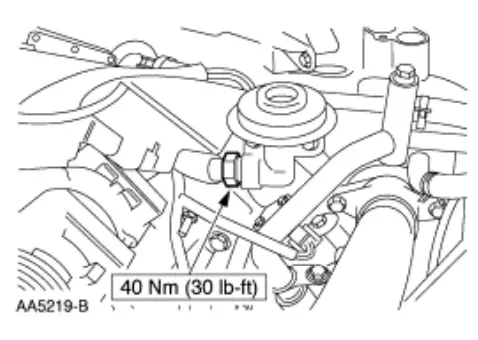
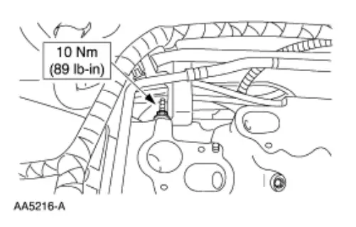
- Remove the bypass tube bolt.

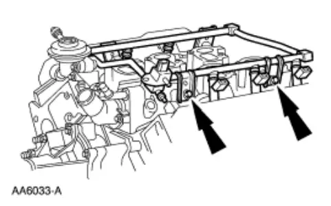
- NOTE: Remove the fuel injection supply manifold and fuel injectors as an assembly.
Remove the fuel injection supply manifold.
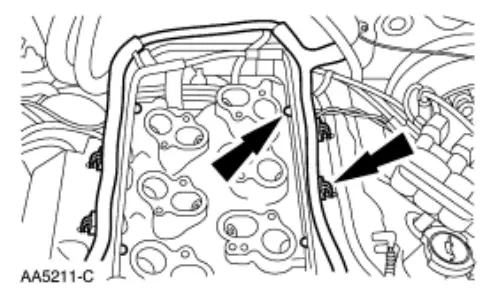
Remove the bolts.
- NOTE: For ease in installation, record the location of the short bolts and the long bolts.
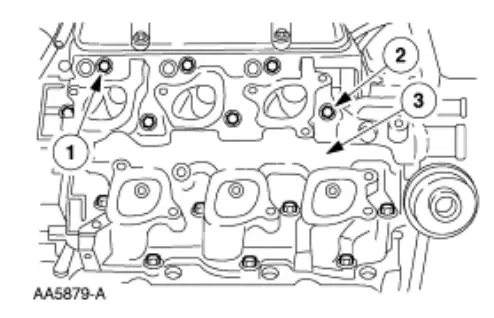
Remove the lower intake manifold (9J447).
1. Remove the eight short bolts.
2. Remove the six long bolts.
3. Remove the lower intake manifold.
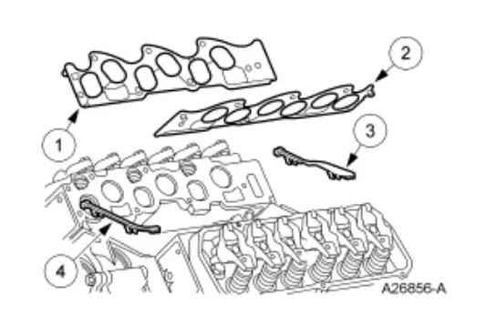
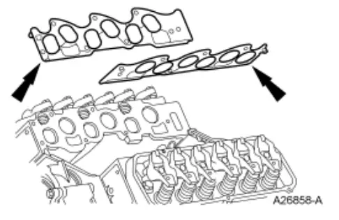
- Remove and discard the intake manifold gaskets (9439).

Item Part Number Description 1 9439 Intake manifold gasket—RH 2 9439 Intake manifold gasket—LH 3 9A424 Intake manifold rear end seal (part of 9439) 4 9A425 Intake manifold front end seal (part of 9439)
Installation
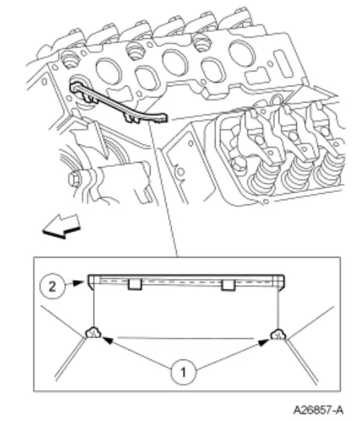
- Install the lower intake manifold front and rear end seals.
1. Apply a bead of sealant to the intake manifold front and rear end seal mounting points as indicated.
Use Silicone Gasket and Sealant F7AZ-19554-EA or equivalent meeting Ford specification WSEM4G323-A4.
3. Install the lower intake manifold front and rear end seals.
- Install the intake manifold gaskets.

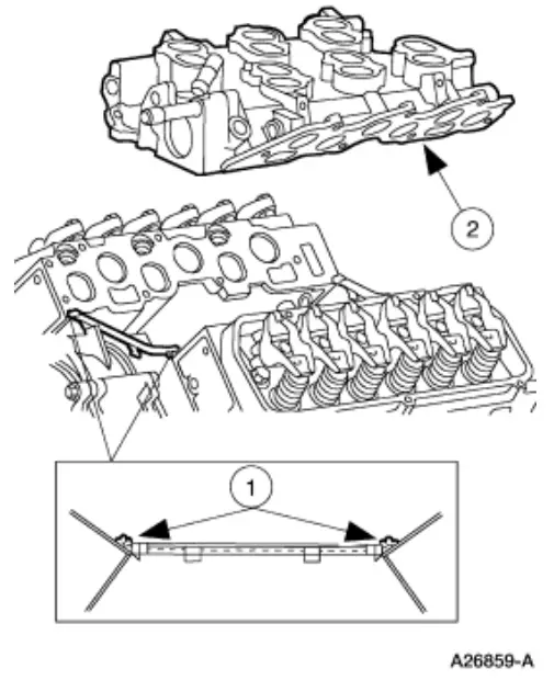
- NOTE: The lower intake manifold must be installed within 4 minutes of applying the sealant.
Position the lower intake manifold.
1. Apply a bead of sealant to the lower intake manifold mounting at the points indicated.
Use Silicone Gasket and Sealant F7AZ-19554-EA or equivalent meeting Ford specification WSEM4G323-A4.
3. Position the lower intake manifold.
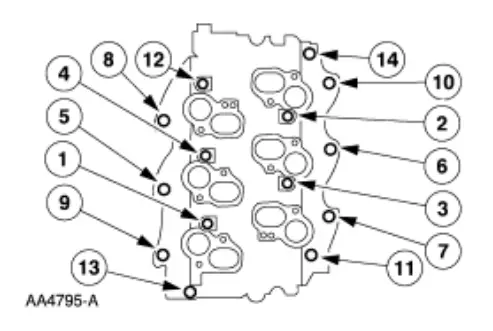
- NOTE: Refer to the location note made during removal and make sure the bolts are installed in the correct location.
Tighten the bolts in sequence in two stages:
• Stage 1: tighten to 5Nm (44 lb-in).
• Stage 2: tighten to 10Nm (89 lb-in).
- NOTE: Install the fuel injection supply manifold and fuel injectors as an assembly.
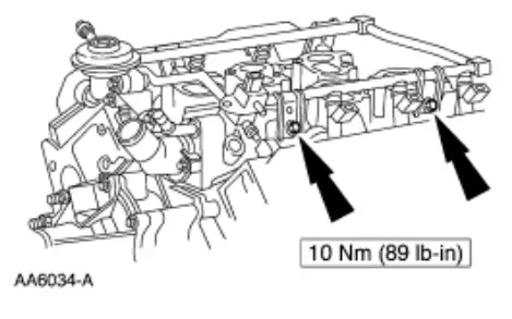
Install the fuel injector supply manifold and bolts.
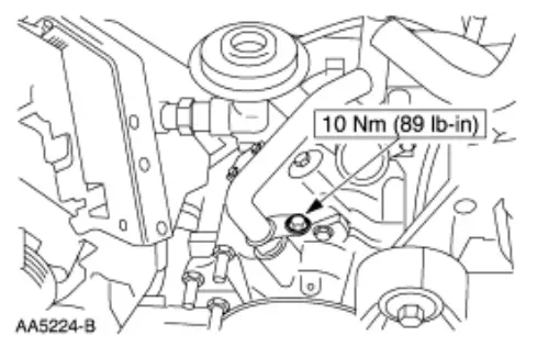
- Install the bypass tube bolt.

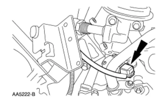
- Connect the electrical connectors.

- Connect the electrical connectors.

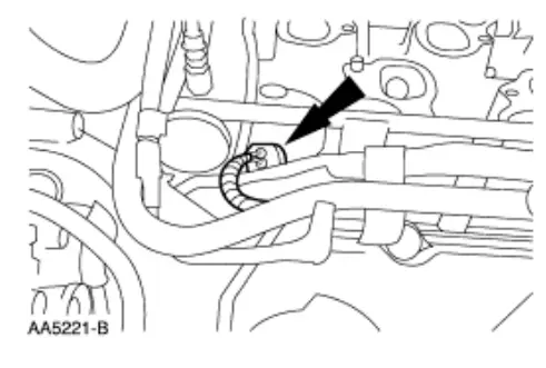
- Connect the coolant hoses.

- Connect the EGR tube.

- Connect the EGR vacuum tube.

- If equipped, install the exhaust air supply valve.
1. Tighten the nut.
2. Connect the air tube.
3. Connect the vacuum tube.
4. Tighten the nuts.
- Install the stud bolt.

- Position the spark plug wire loom.

- Connect the heater hose.

- Position and connect the engine wire harness. Install the pin-type retainers.

- Connect the fuel injection supply manifold. For additional information, refer to Section 310-00.
- Connect the fuel pressure electrical connector.

- Install the upper intake manifold. For additional information, refer to Intake Manifold — Upper in this section.
- CAUTION: Proper cooling system bleeding is critical for correct engine cooling.
Fill and bleed the cooling system. For additional information, refer to Section 303-03.
1/13/22, 9:35 PM
2000 Ford Mustang • MotoLogic


