![]()
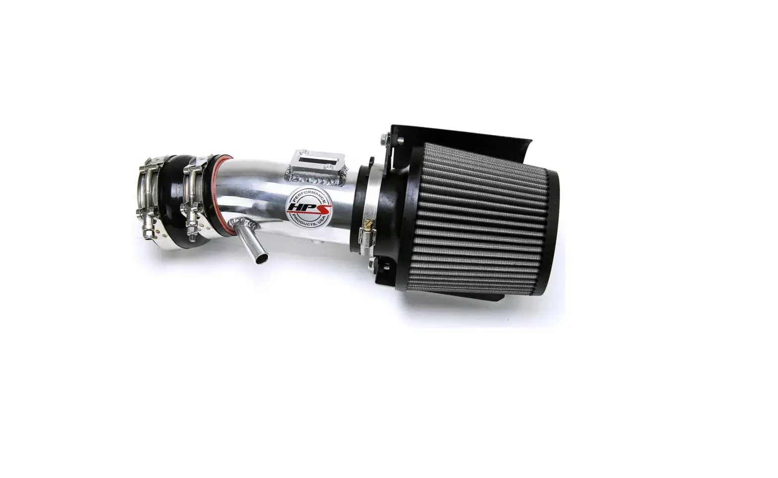
Performance Air Intake Kit
Part Number: 827-604
1999-2004 Nissan Frontier 3.3L V6
Non Supercharged
2000-2004 Nissan Xterra 3.3L V6
Non Supercharged
Installation Instructions
For technical inquiries please email us at [email protected]
In the email, please include the following information for faster response:
- Year / Make / Model / Engine of your vehicle
- If it is a fitment issue, please include pictures showing the fitment problem.
- If there are missing parts, please list the part number(s) from the bill of materials on the 2nd page.
- Optional but recommended – Your contact phone number and preferred call back time.
You can also give us a call via 626-747-9200 for tech support Monday-Friday, 9:00am-5:00pm Pacific Time.
Last revision KC03212023
Bill of Materials
Kit Number: 827-604
Line | Description | Part Number | Qty |
| 1 | Intake Pipe | 529-352 | 1 |
2 | HPS Air Filter | HPS-4276 | 1 |
| 3 | Heat Shield | HS-404WB | 1 |
4 | Intake Bracket | 530-353 | 1 |
| 5 | 2.75″ – 3.00″ Reducer x 3″ Long | P3SR-275-300-L3 | 1 |
6 | 3.00″ – 3.12″ Reducer x 2″ Long | P3SR-300-312-L2 | 1 |
| 7 | T-Bolt Clamp for 3.18″ Hose | SSTC-83-91 | 1 |
8 | T-Bolt Clamp for 3.00″ Hose | SSTC-79-87 | 2 |
| 9 | T-Bolt Clamp for 2.75″ Hose | SSTC-73-81 | 1 |
10 | Worm Gear Clamp | EMSC-80-100 | 1 |
| 11 | Vacuum Hose 4mm x 12″ Inches | HTSVH4-BLK | 1 |
12 | MAF Adapter | MAF-003 | 1 |
| 13 | 6mm Bolt x 16mm Long | HW-B6-16 | 3 |
14 | 6mm Bolt x 20mm Long | HW-B6-20 | 1 |
| 15 | 6mm Flange Nut | HW-N6 | 7 |
16 | 6mm Flat Washer x 16mm OD | HW-FW6L | 7 |
| 17 | 6mm Rubber Vibration Mount x 1/2″ Tall | HW-RM6-50 | 1 |
18 | 6mm Rubber Vibration Mount x 1″ Tall | HW-RM6-100 | 1 |
| 19 | 1/8″ Vacuum Cap | HW-VC-012 | 1 |
- Report any defective or missing parts to HPS directly. The authorized HPS dealer you purchased this product from might not have the correct parts you need.
- Before installing any parts of this system, please read the instructions thoroughly.
- Installation DOES require some mechanical skills. A qualified mechanic is highly recommended.
- Do not attempt to install the intake system while the engine is hot.
- The installation may require removal of radiator fluid lines that may be hot.
- For technical inquiries, please e-mail us at [email protected]
PLEASE READ CAREFULLY BEFORE INSTALLATION!
This installation is not for the novice customer Install this system with EXTREME caution! Misuse of this product can destroy your engine! If you are not well versed in the installation of intakes and if you are not mechanically inclined, please have a tuner shop install this kit.
NOTE: HPS holds no responsibility for any engine damage that results from misuse of this product.
GETTING STARTED
1. Turn the ignition OFF and disconnect the vehicle’s negative battery cable. If the engine has run within the past two hours let it cool down.
NOTE: Disconnecting the negative battery cable erases pre-programmed electronic memories. Write down all memory settings before disconnecting the negative battery cable. Some radios will require an anti-theft code to be entered after the battery is reconnected. The anti-theft code is typically supplied with your owner’s manual. In the event your vehicles’ anti-theft code cannot be recovered, contact an authorized dealership to obtain your vehicles anti-theft code. We also highly recommend NOT discarding any stock parts after the installation.
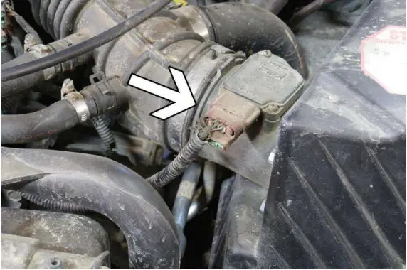
2. Disconnect the electrical connector on the Mass Air Flow sensor.
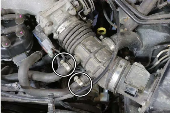
3. Using a pair of pliers, squeeze the hose clamps to loosen the breather hoses from the intake tube.
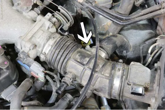
4. Loosen the hose clamp and disconnect the stock intake resonator from the intake tube.
5. Unclip the two retaining clips securing the upper air box from the lower air box, then loosen the hose clamp from the intake tube to the upper air box.
6. Remove the upper air box assembly from the vehicle. Loosen the hose clamp securing the intake tube from the throttle body.

7. Remove the stock intake tube from the vehicle.
8. Remove the three bolts securing the lower air box assembly.

9. Disconnect the front resonator from the lower air box and remove the air box from the vehicle.
10. Disconnect the electrical connector from the air temperature sensor then remove the bolt securing the front air resonator.

11. Remove the front air resonator from the vehicle and remove the air temperature sensor from the resonator.
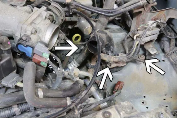
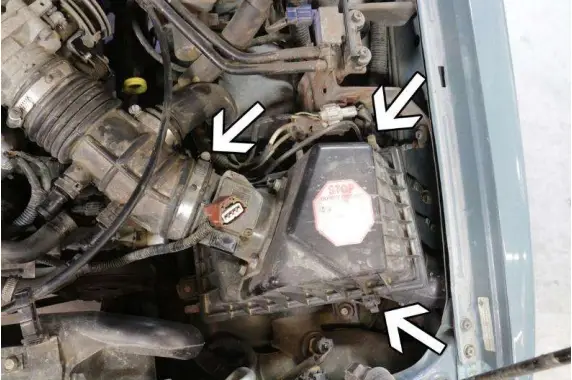
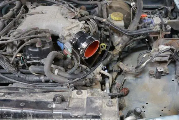
12. Disconnect the electrical harness clip from the intake resonator, then remove the two bolts securing the intake resonator.
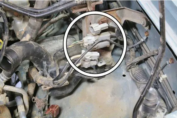
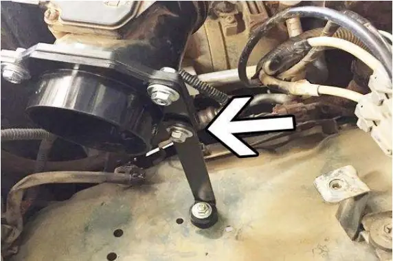
13. Disconnect the three electrical connectors in the image shown above.

14. Remove the intake resonator from the vehicle.
15. Unbolt the air box bracket and remove the bracket from the vehicle.
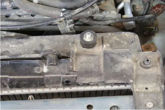
16. Install the 1″ rubber vibration mount for the cruise control bracket.
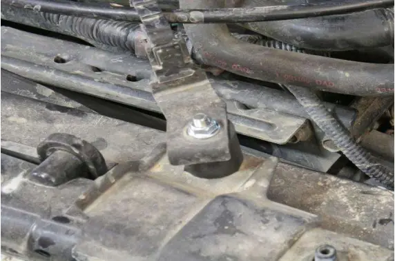
17. Install the cruise control bracket and secure the bracket with a nut and washer supplied in the hardware kit.
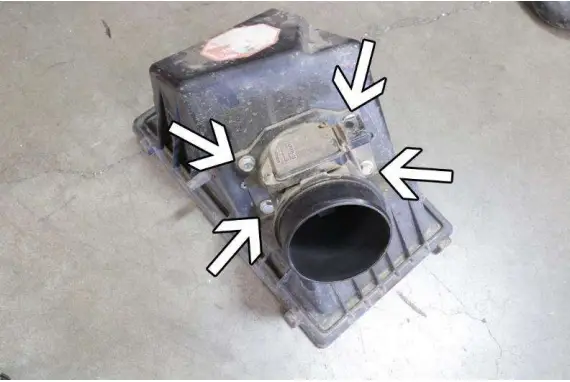
18. Remove the four bolts securing the Mass Air Flow sensor housing and detach the housing from the air box.
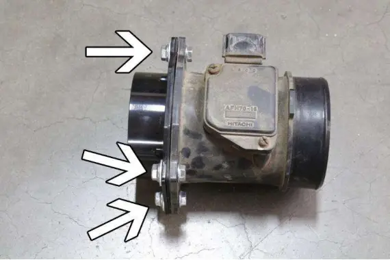
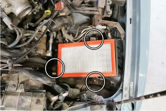
19. Install the supplied MAF adapter using the three 6mm x 16mm on the three areas located shown above. *NOTE* The fourth hole will be used for the intake bracket.
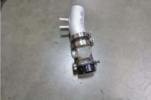
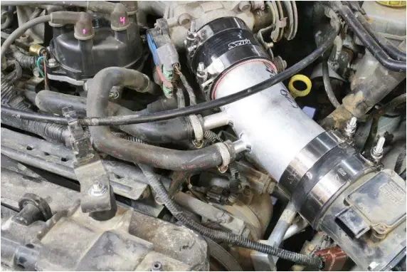
20. Install the reducer coupler along with the T-bolt clamps onto the MAF sensor housing and insert the HPS intake pipe into the coupler. Do not tighten the clamp for the intake pipe yet because the intake pipe will need to be re-positioned.
21. Install the reducer coupler onto the throttle body along with the T-bolt clamps included in the hardware kit.
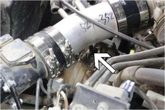
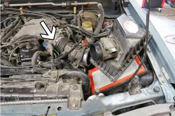
22. Insert the intake pipe into the throttle body coupler. Install the vacuum hose onto the bung indicated in the image above. Install the vacuum cap provided in the hardware kit if the vehicle is not equipped with the MAP switch solenoid valve.
23. Adjust the intake pipe to the proper position and re-insert the breather hoses onto the intake barbs.
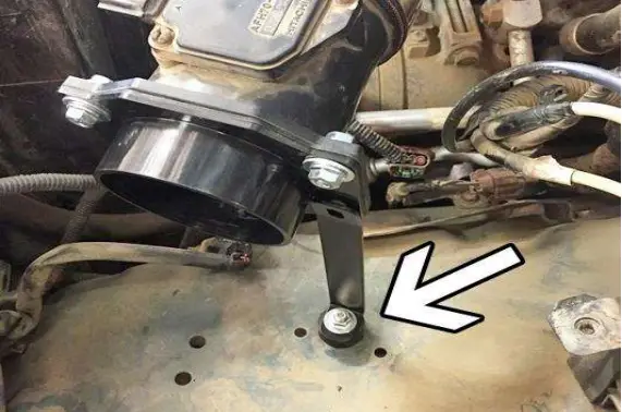
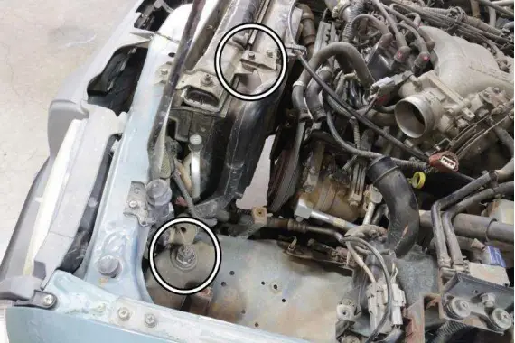
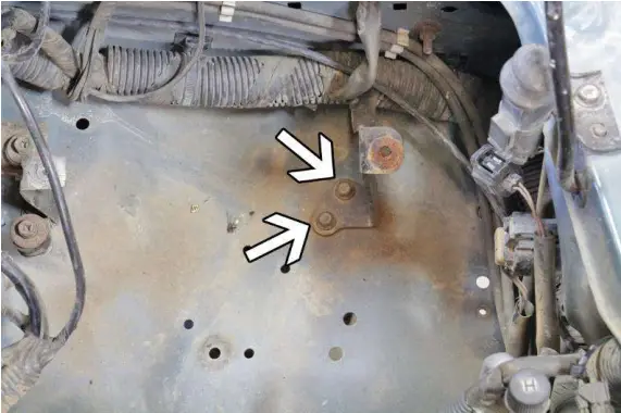
24. Install the ½” vibration mount into the indicated area shown above. Secure the vibration mount using a nut and washer under the wheel well. Install the intake bracket onto the vibration mount.
25. Using the 6mm x 20mm bolt secure the intake bracket to the MAF sensor housing.
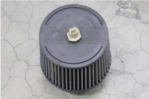
26. Install the air temperature sensor into the provided HPS air filter.
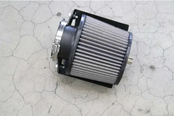
27. Install the heatshield onto the air filter using the provided worm gear clamp included in the hardware kit.
28. Install the air filter onto the MAF sensor housing and reconnect the air temperature sensor.
Final Steps
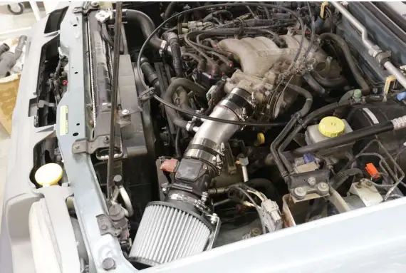
Once the intake has been positioned, tighten all the clamps and secure all the parts.
Upon completion of the installation, reconnect the negative battery terminal before you start the engine. Double check to make sure everything is tight and properly positioned before starting the vehicle.
Start the engine. Let the car idle for 3 minutes. Perform a final inspection before driving the vehicle. Listen carefully for any odd noises, rattles and/or air leaks prior to taking it for a test drive. If any problems arise go back and check the vacuum lines, hoses and clamps that may be causing leaks or rattles and correct the problem.
Periodically, recheck the alignment of the intake system and make sure there is proper clearance around and along the length of the intake. Failure to follow proper maintenance procedures may cause damage to the intake and will void the warranty.
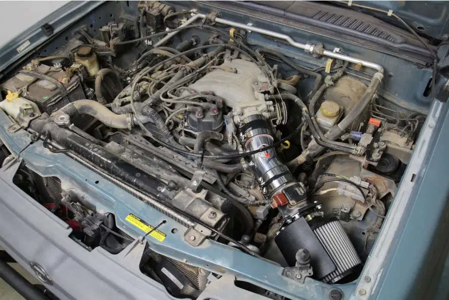
HPS Performance Air Intake Kit with Heat Shield | Part Number 827-604
Nissan 00-04 Xterra 3.3L V6 Non Supercharged
Nissan 99-04 Frontier 3.3L V6 Non Supercharged


