 Ford F 150 Workshop Fuel Injection Supply Manifold User Manual
SECTION 303-04B: Fuel Charging and Controls — 4.6L (2V) and 5.4L (2V) REMOVAL AND INSTALLATION
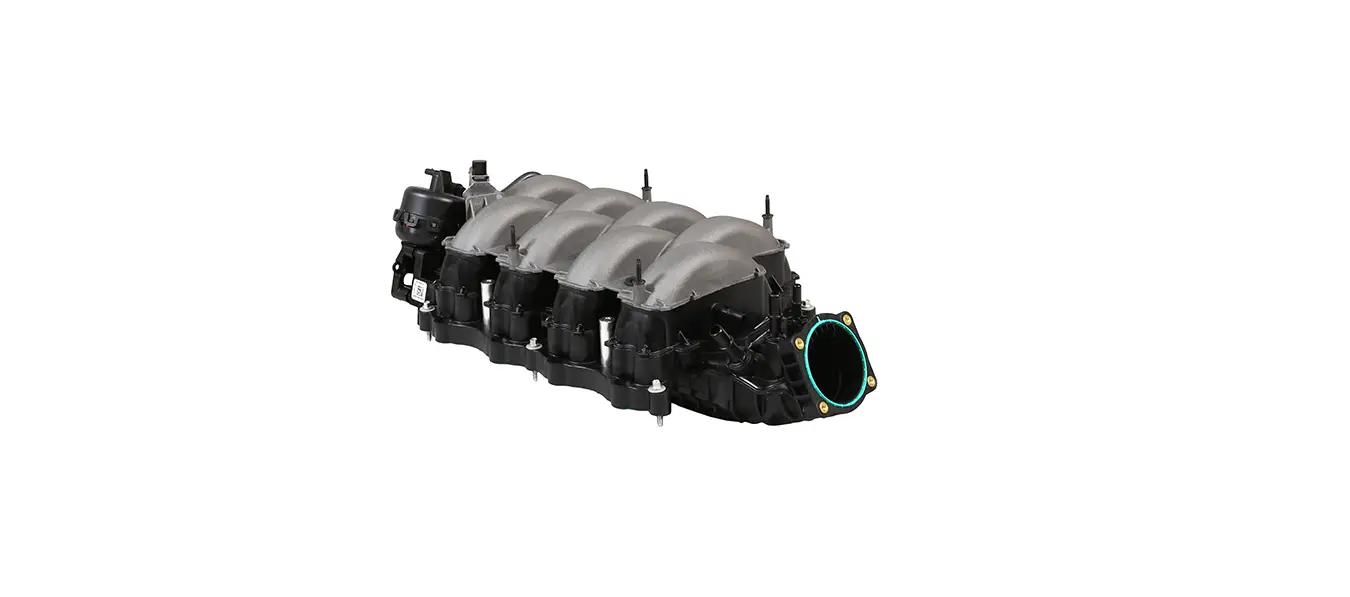
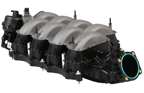
Fuel Injection Supply Manifold—Fuel Injection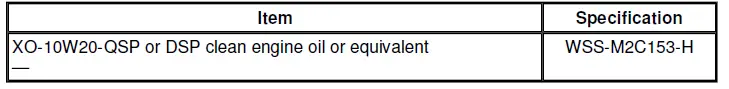
WARNING
Do not smoke or carry lighted tobacco or open flame of any type when working on or near any fuel-related components. Highly flammable mixtures are always present and may be ignited. Failure to follow these instructions may result in personal injury.
WARNING
Fuel in the fuel system remains under high pressure even when the engine is not running. Before working on or disconnecting any of the fuel lines or fuel system components, the fuel system pressure must be relieved. Failure to follow these instructions may result in personal injury.
All engines
- Disconnect the battery ground cable (14301). For additional information, refer toSection 414-01.
- Relieve the fuel pressure. For additional information, refer toSection 310-00A.
- Partially drain the cooling system. For additional information, refer toSection 303-03A or Section 303-03B.
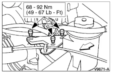
- Remove the power steering reservoir bracket.
- Remove the bolts.
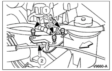
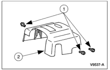
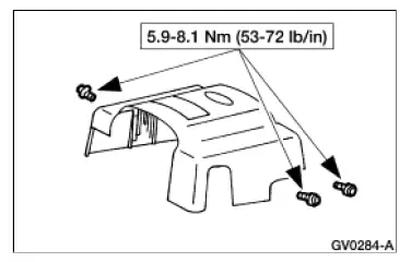
- Position the power steering reservoir bracket out of the way. Remove the accelerator control splash shield. Remove the bolts. Remove the accelerator control splash shield.

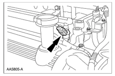
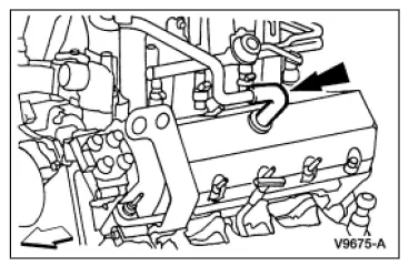
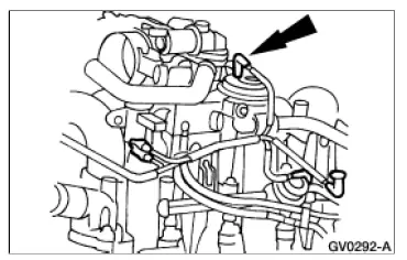
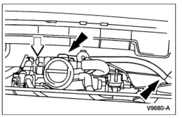
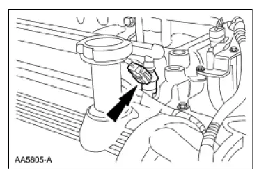
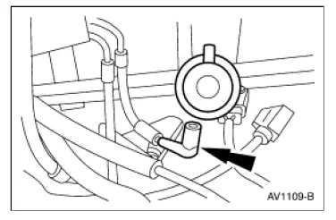
- Disconnect the fuel pressure regulator valve vacuum hose.
- CAUTION: After disconnecting, plug the fuel lines to prevent leakage.Disconnect the fuel lines. For additional information, refer toSection 310-00A. Disconnect the eight ignition coil electrical connectors.

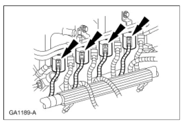
- Disconnect the eight fuel injector electrical connectors.
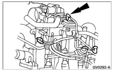
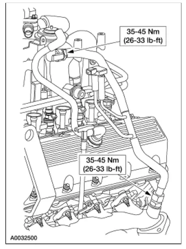
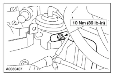
- Remove the nut and disconnect the brake booster vacuum hose and bracket
- Remove the brake booster bracket and tube. Remove the nut. Release and move the two hose clamps. Remove the brake booster tube.
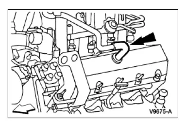
- Remove the positive crankcase ventilation (PCV) hose.
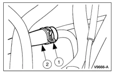
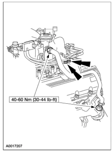
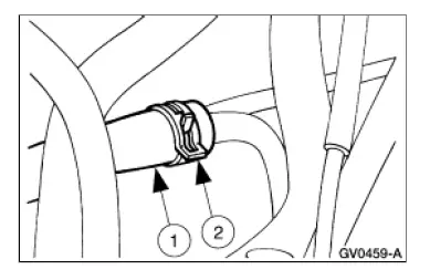
- Disconnect the water heater inlet tube hose. Release and move the hose clamp. Disconnect the water heater inlet tube hose and position aside.
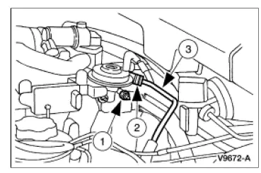
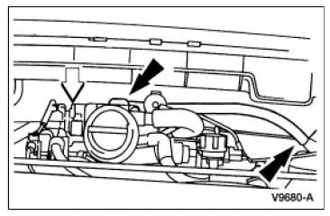
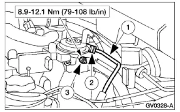
- Disconnect the EGR connections:
- EGR valve to exhaust manifold tube upper fitting
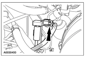
- Differential pressure feedback EGR transducer electrical connector
- EGR valve to exhaust manifold tube lower fitting
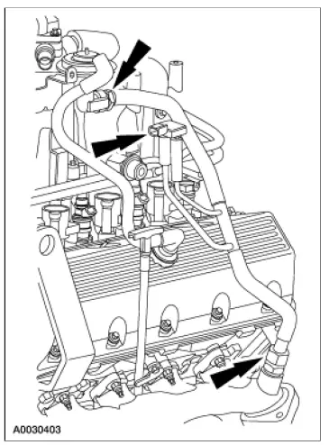
- Disconnect the exhaust gas recirculation (EGR) valve to exhaust manifold tube.
- Disconnect the two differential pressure feedback EGR transducer hoses.
- Remove the EGR valve to exhaust manifold tube upper fitting.
- Remove the EGR valve to exhaust manifold tube lower fitting.
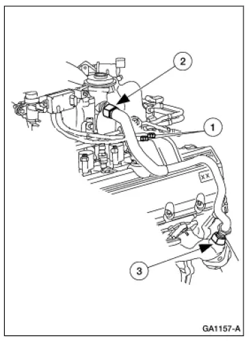
- Remove the EGR tube.
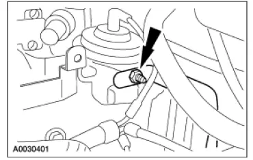
- Disconnect the EGR valve vacuum hose.
- Disconnect the vapor management valve (VMV) hose.
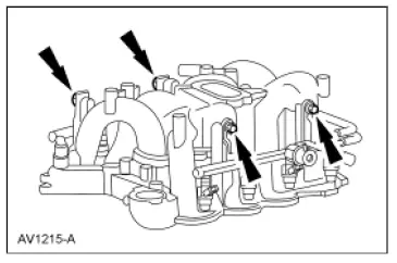
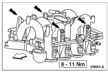
- Remove the bolts and lift the fuel injection supply manifold (9F792) and injectors upward, out of the intake manifold (9424).
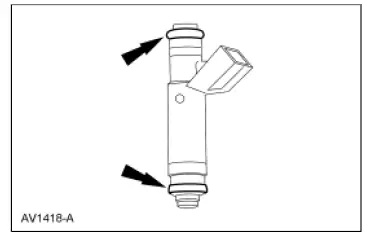
- Remove the fuel injectors from the fuel injection supply manifold.
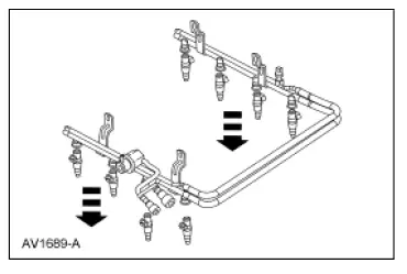
- Inspect the two O-ring seals from each fuel injector. Install new O-ring seals as needed.
Installation
All engines
- NOTE: Lubricate the new O-ring seals with clean engine oil to aid installation. Install two O-ring seals to each fuel injector.
- Install the fuel injectors into the fuel injection supply manifold.
- Install the four bolts.
- Connect the VMV hose.
- Connect the EGR valve hose.
- Position EGR tube on the engine.
- Install the exhaust manifold-to-EGR valve tube.
- Connect the differential pressure feedback EGR transducer electrical connector.
- Install the exhaust manifold-to-EGR valve tube and connect the differential pressure feedback EGR transducer hoses.
- Install the PCV hose.
- Connect the brake booster vacuum hose and bracket and install the nut.
- Install the brake booster bracket and tube. Install the brake booster tube. Install the two hose clamps. Install the nut.
- Connect the water heater inlet tube hose. Connect the water heater inlet tube hose. Compress and install the hose clamp.
- Connect the eight fuel injector electrical connectors.
- Connect the eight ignition coil electrical connectors.
- Connect the fuel lines. For additional information, refer toSection 310-00A.
- Connect the fuel pressure regulator valve vacuum hose.
- Install the accelerator control splash shield.
- Install the power steering reservoir bracket.
- Connect the battery ground cable. For additional information, refer to Section 414-01.
- Fill the cooling system. For additional information, refer toSection 303-03A or Section 303-03B. Downloaded from http://www.fordtechservice.dealerconnection.com/pubs/content/… 10/24/2009


