![]()
2014 F-150
User Manual
Electronic Engine Controls – Camshaft Position (CMP) Sensor – 5.0L (4V) – Removal and Installation
2014 F-150
 | 303-14 Electronic Engine Controls | 2014 F-150 |
| REMOVAL AND INSTALLATION | Procedure revision date: 06/02/2016 |
Camshaft Position (CMP) Sensor — 5.0L (4V)
Removal
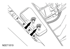
Both RH and LH intake Camshaft Position (CMP) sensors and RH exhaust CMP sensor
- Disconnect the Camshaft Position (CMP) sensor electrical connector.
- Remove the bolt and the CMP sensor.
LH exhaust Camshaft Position (CMP) sensor - Position the vehicle on a hoist. For additional information, refer to Section 100-02.
- If equipped with 4 wheel drive, remove the transfer case. Section 308-07B
- If equipped, remove the 2 bolts and the LH heat shield from the rear of the LH cylinder head.
- Disconnect the LH CMP sensor electrical connector.
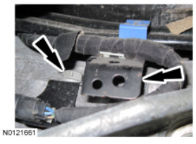
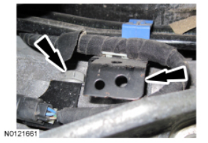
- Disconnect the LH HO2S and the LH CMS electrical connectors, and remove the pushpins from the fuel line bracket.
- Position the LH HO2S and the LH CMS harness from the top of the transmission
- Remove the fuel line bracket bolt from the left side of the transmission and position the fuel lines and bracket aside.

- Remove the CMP sensor bolt.
- NOTE: Make sure the transmission jack contacts the outer ribs of the transmission fluid pan.
2 wheel drive vehicles, position a suitable high-lift transmission jack under the transmission and remove the 2 transmission support insulator nuts. All vehicles, raise the transmission until the CMP sensor can be removed.
• Remove the CMP sensor.
Installation
LH exhaust Camshaft Position (CMP) sensor
- NOTE: The bolt must be torqued while the transmission is raised Position the Camshaft Position (CMP) sensor and install the bolt.
Tighten to 10 Nm (89 lb-in). - All vehicles, using the suitable high-lift transmission jack, lower the transmission. 2 wheel drive vehicles, install the 2 transmission support insulator nuts.
Tighten to 103 Nm (75 lb-ft).
- Position the fuel lines and bracket back and Install the bolt.
Tighten to 25 Nm (18 lb-ft).
- Position the LH CMS and the LH HO2S harness back over the top of the transmission.
- Install the harness pushpins to the fuel line bracket and connect the LH sideCMS and LH side HO2S electrical connectors.
- Connect the CMP sensor electrical connector.
- If equipped, position the LH heat shield onto the rear of the LH cylinder head and install the 2 bolts.
Tighten to 10 Nm (89 lb-in). - If equipped with 4 wheel drive, Install the transfer case. Section 308-07B
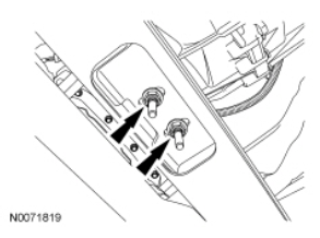
Both RH and LH intake CMP sensors and RH exhaust CMP sensor - Position the CMP sensor and install the bolt.
Tighten to 10 Nm (89 lb-in). - Connect the CMP sensor electrical connector.
Copyright © 2018 Ford Motor Company