luminii LETO 44 Mini P 954 Semi-Recessed Canopy
Read and follow these instructions before installing or maintaining this product
- This product is suitable for DRY INDOOR LOCATIONS ONLY
- Make sure this product is NOT on the same circuit as inductive loads, (e.g. fluorescent bulbs, discharge bulbs, ventilation fans, etc…)
- Do not switch on line voltage until all wiring is complete
- Incorrect wiring will result in irreparable damage to LED and power supply
- This product should only be installed by a licensed electrician
Warranty
- This product must be installed in accordance with all applicable installation codes and ordinance.
- Limited five (5) years warranty · Warranty is void in the eventuality of unauthorized modifications and/or improper use
INSTALLATION INSTRUCTION
Pendant: Single Feed Cable (AC Connection)
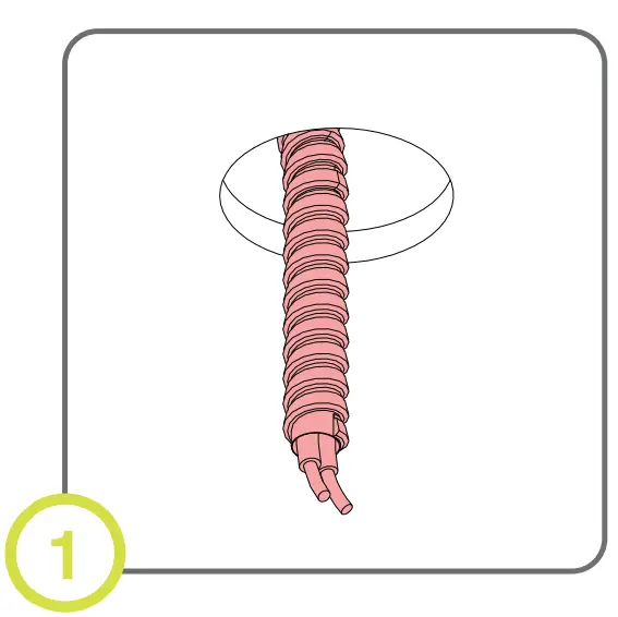
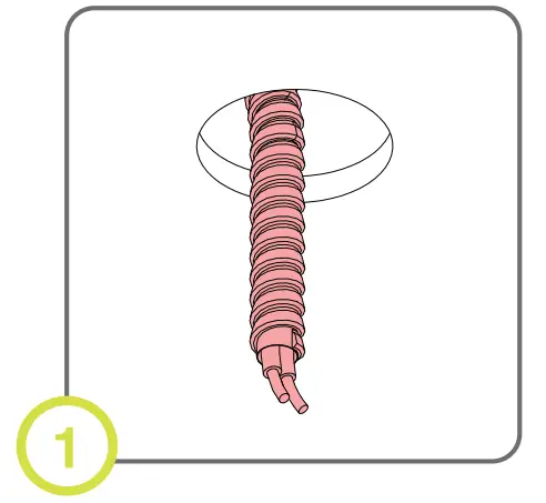
- Finish ceiling installation. Make sure hole is cut to appropriate size and location. 54mm (2.125”)

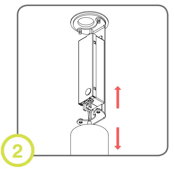
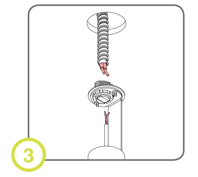
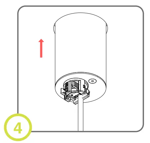
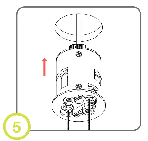
- Disassemble driver housing to expose the driver.

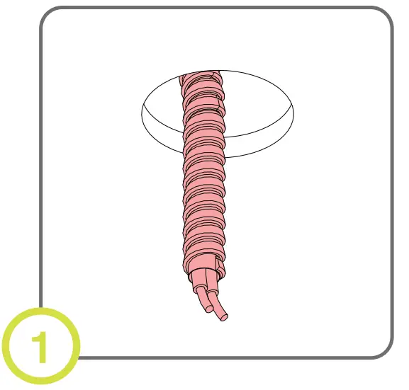
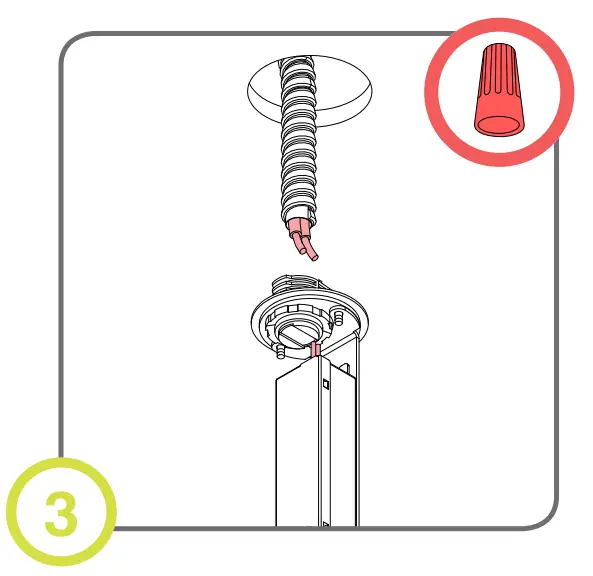
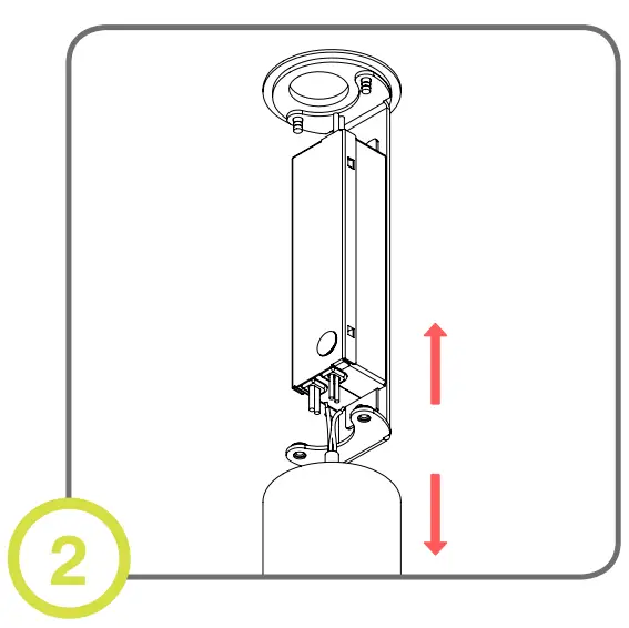
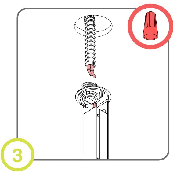
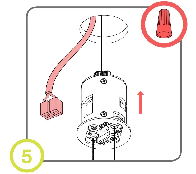
- Make electrical connections and use appropriate strain relief.

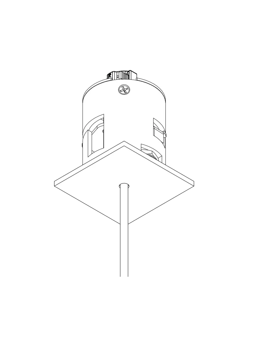
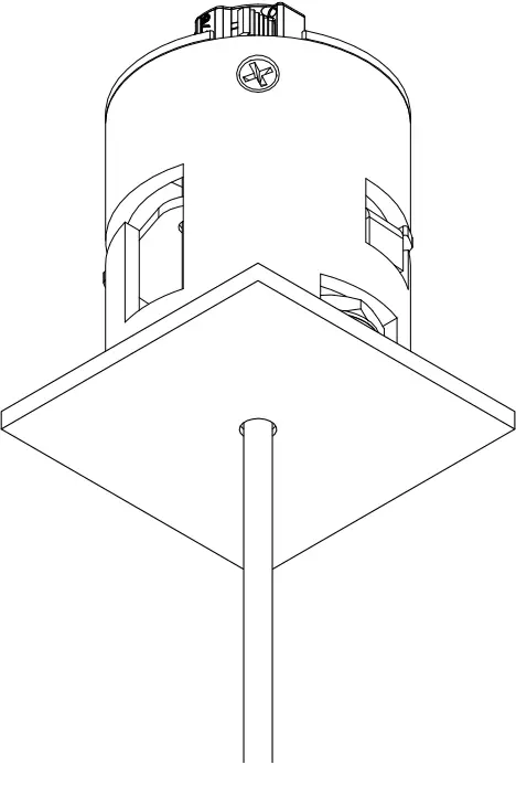
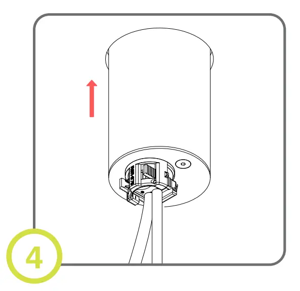
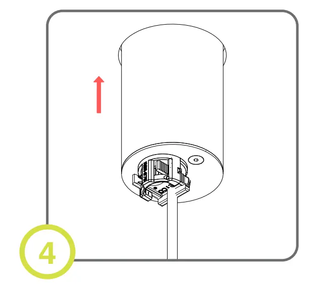
- Reassemble housing and insert into ceiling. Push aside to leave room for canopy
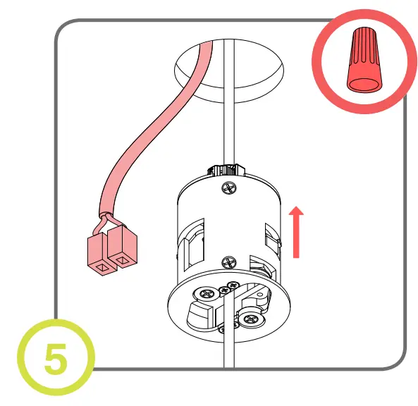
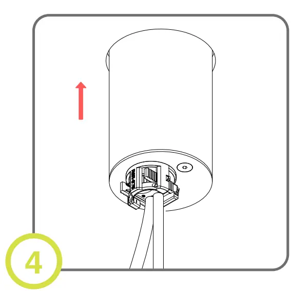
- Connect dimming controls to included cable clamps. Insert wires and canopy into ceiling.
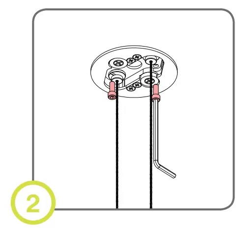
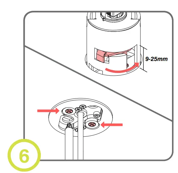
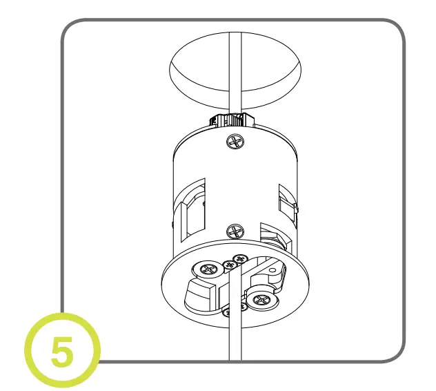
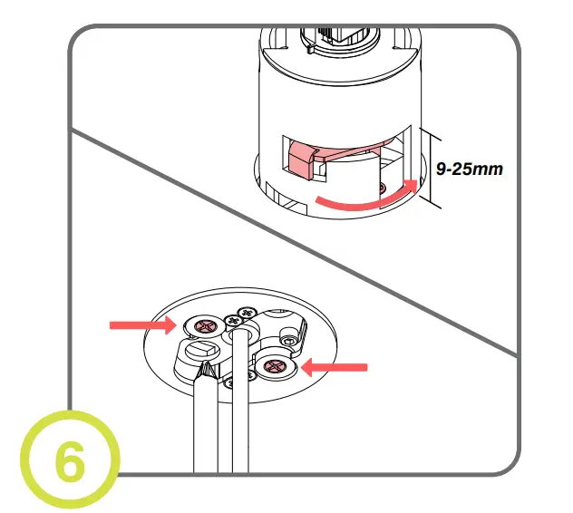
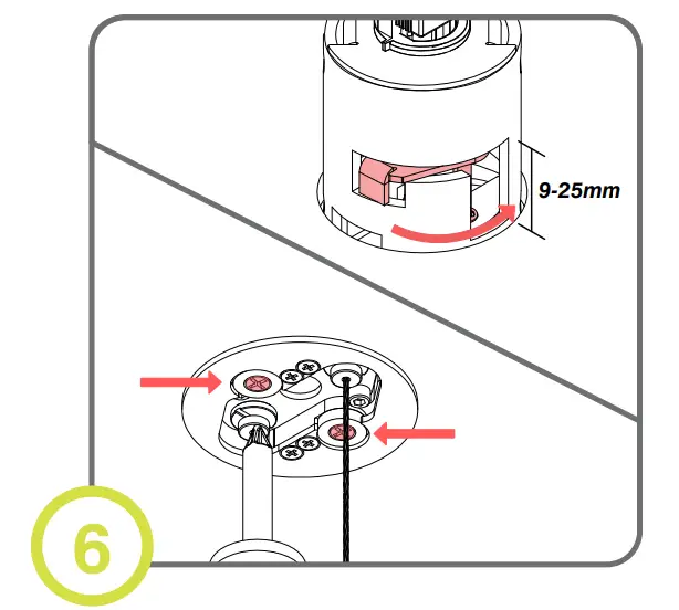
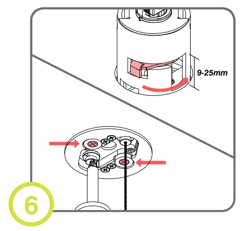
- Turn screws until housing is secured in place (arms will rotate and clamp down on ceiling)
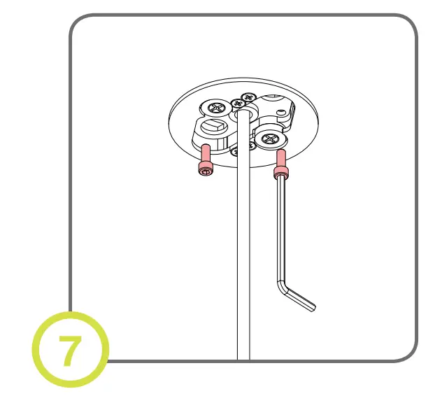
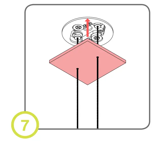
- Unscrew gripper plate and separate from canopy.

- Unscrew gripper plate and separate from canopy
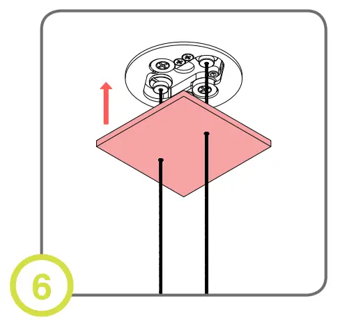
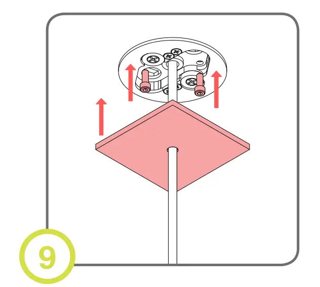
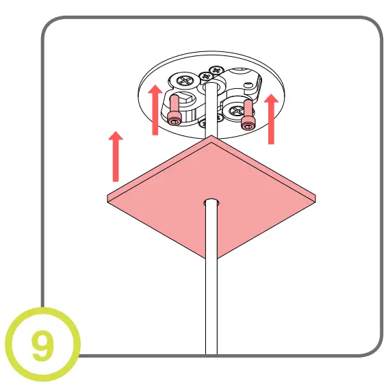
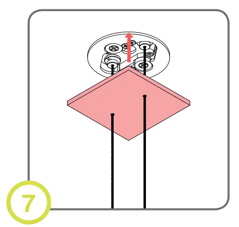
- Re-attach gripper to canopy and slide trim plate up until held in place by magnets.

Pendant: Single Feed Cable (Remote DC Connection)
- Finish ceiling installation. Make sure hole is cut to appropriate size and location. 54mm (2.125”)
- Disassemble driver housing to expose fixture wiring. Cylinder housing is used as DC junction box.
- Make electrical connections and use appropriate strain relief.
- Reassemble housing and insert into ceiling. Push aside to leave room for canopy.
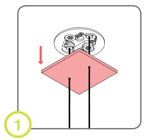
- Insert canopy into ceiling.
- Turn screws until housing is secured in place (arms will extend and clamp down on ceiling)
- Unscrew gripper plate and separate from canopy.
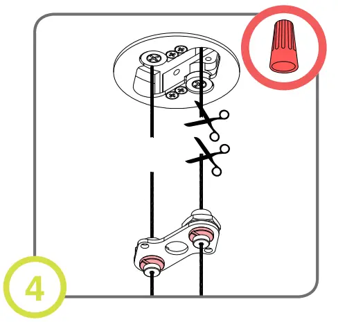
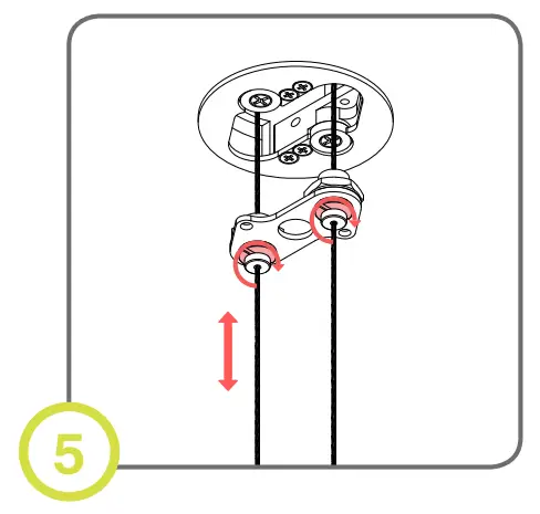
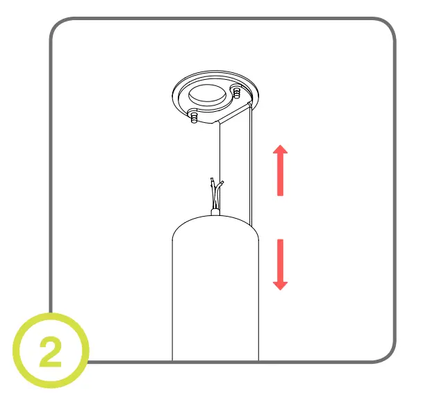
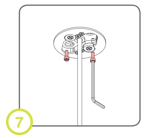
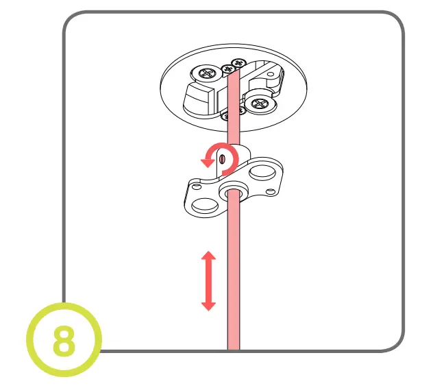
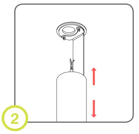
- Loosen set screw and adjust cable to desired height. Cut and reconnect wire if needed.
- Re-attach gripper to canopy and slide trim plate up until held in place by magnets.

Pendant: Powered Aircraft Cable (Remote DC Connection)
- Finish ceiling installation. Make sure hole is cut to appropriate size and location. 54mm (2.125”)
- Disassemble driver housing to expose the driver.
- Make electrical connections and use appropriate strain relief.
- Reassemble housing and insert into ceiling. Push aside to leave room for canopy.
- Connect dimming controls to included cable clamps. Insert wires and canopy into ceiling.

- Turn screws until housing is secured in place (arms will extend and clamp down on ceiling)

- Slide trim plate up until held in place by magnets.

Pendant: Powered Aircraft Cable (Remote DC Connection)
- Finish ceiling installation. Make sure hole is cut to appropriate size and location. 54mm (2.125”)

- Disassemble driver housing to expose fixture wiring. Cylinder housing is used as DC junction box.

- Make electrical connections and use appropriate strain relief

- Reassemble housing and insert into ceiling. Push aside to leave room for canopy

- Insert canopy into ceiling
- Turn screws until housing is secured in place (arms will extend and clamp down on ceiling)
- Slide trim plate up until held in place by magnets
Pendant: Powered Aircraft Cable (Remote DC Connection)
- Remove trim plate from the canopy
- Unscrew gripper plate separate from canopy.
- Loosen set screw and adjust cable to desired height.
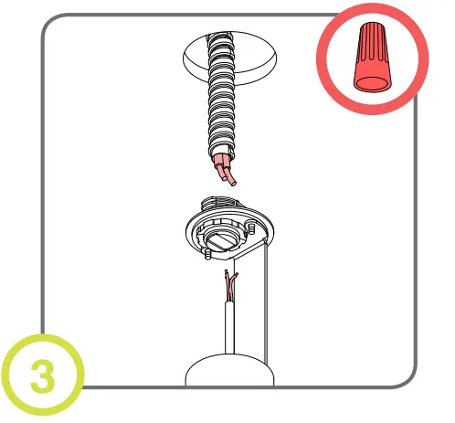
- Cut excess cable leaving ~3” above gripper. Make electrical connections using appropriate hardware
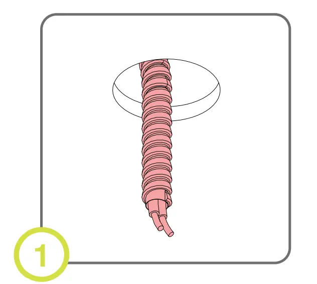
- If cables develop a twist, loosen set screw and cycle cable through the gripper 4-5 times.
- Tighten screws, re-attach gripper plate to canopy and slide trim plate up until held in place by magnets.