POTTER SCM24W-153075 Select A Strobe Chime Combination Owner’s Manual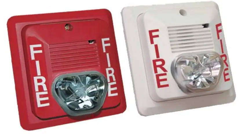
- Meets or exceeds NFPA/ANSI Standards and ADA Accessability Guidelines
- UL Listed for wall mounting
- Screw terminal capacity up to AWG #12
- Universal mounting plate included
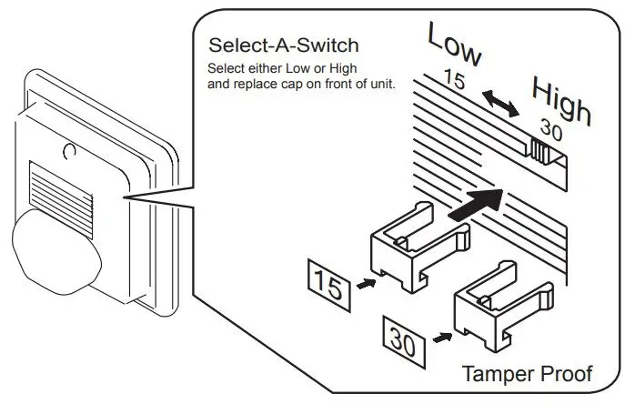
- Selectable settings: 15cd or 30cd
- Polarized strobes with wide operating voltage range using fi ltered
DC or unfi ltered FWR input voltage - Horn fi eld selectable tones:
- 2700 Hz or 2400 Hz
- Temporal or Non-temporal
- High or Low dBA Output
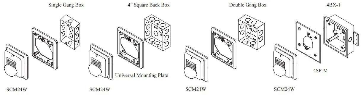
- Mounts to 4” square, single gang, double gang, or octagonal back box
- Tamper-proof candela selector switch
- Synchronization requires Sync Module (SMD10-3A)
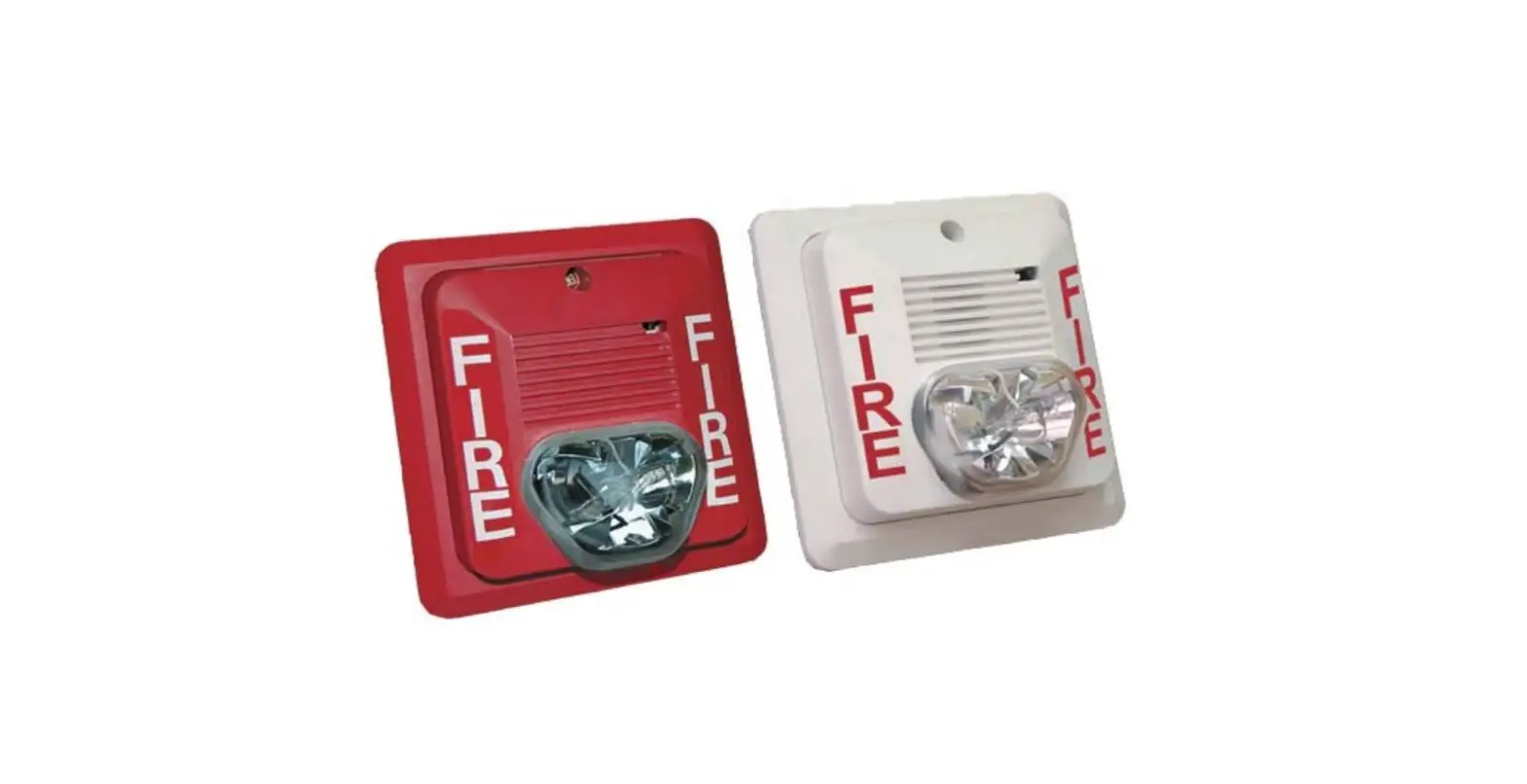
- Available in red or white housing
Amseco’s Select-A-Strobe/Chime Series is designed to provide audible (private mode) for fi re alarm protection systems. It complies with ADAand meets or exceeds NFPA/ANSI audible emergency evacuation signal and UL 464 (private mode) 1971. The SCM24W Series features a unique candela intensity fi eld selector switch for alternating the candela output 15cd to 30cd (75cd on axis). The chime provides two different selectable tones and a high/low output setting that can be achieved with the use of mini-jumpers located on the back of the unit. These appliances are polarized for connecting to supervised fi re alarm circuits. The strobe is designed with a xenon fl ash tube and provides a candela intensity fi eld selector switch for maximum performance.
The SCM24W-153075 can be synchronized by using the SMD10-3A Sync Module to comply with NFPA recommendations concerning photosensitive epilepsy when installing two or more visual appliances within the fi eld of view. The strobe signals are listed for indoor use, wall mount, under UL1971 standard.
Ordering Information
| Model Number | Housing Color | Input Voltage | Operating Voltage Range | Selectable Strobe Output (cd) | Horn Sound Ouput | Wiring Type | Mounting Type | Sync Module | Operating Temperature Range |
| SCM24W-153075R | Red | Regulated 24V DC/ FWR | 16-33 VDC16-33 VFWR | 15 or 30 | Selectable | Terminals | Wall | SMD10-3A | 32°F – 120°F (0°C – 49°C) |
| SCM24W-153075W | White |
Engineering Specifications
The audible and visual alarm indicating appliances shall be Amseco model SCM24W 153075 or equivalent device. The chime shall be listed under UL 1971 Standard for signaling devices for the hearing impaired and shall be approved for fi re protective service. The candela output shall be fi eld selectable, having a dual setting of 15cd or 30cd output. The chime shall provide two different fi eld selectable temporal or steady tones, and a high/low fi eld selectable output setting. The signaling strobe shall operate on a 24V DC coded system. The strobe shall be designed to produce one signal fl ash per second with continuously applied minimum voltage. The strobe/chime shall have a universal back mounting plate, capable of wall mounting to a back box. When strobe synchronization is required, the SCM24W-153075 shall be compatible with the Amseco SMD10-3A (daisy chain) or other source of Amseco sync protocol. Audible and visual signaling devices shall be installed in accordance with current NFPA guidelines.
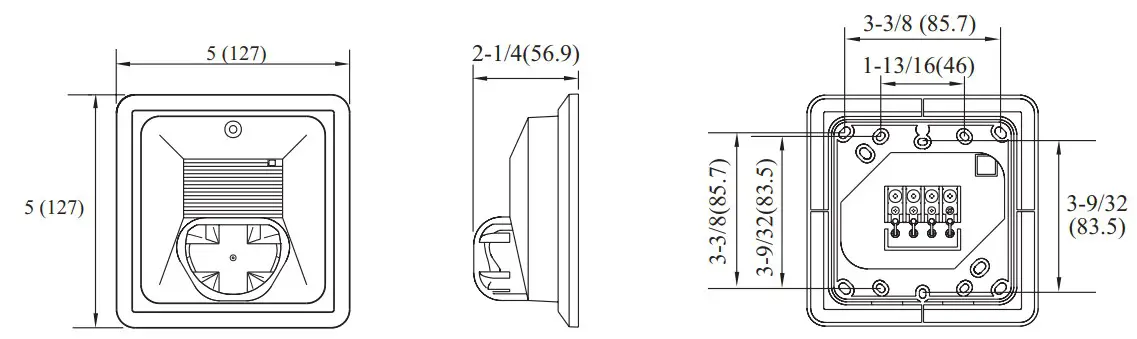
Dimensions inches (mm)
![]() WARNING
WARNING
Strobes must be used only on circuits with continuously operating voltage. DO NOT use strobe on coded or interrupted circuits in which the applied voltage is interrupted ON and OFF as the strobe may fail to fl ash. The applied voltage must be within its rated input voltage range. Fuse ratings on signaling circuits must handle peak currents from all devices connected to those circuits.
| UL Required Minimum Light Output | Horizontal | Vertical | |||
| 15cd | 30cd | 15cd | 30cd | ||
| DEGREES | 0 | 75.00 | 75.00 | 75.00 | 75.00 |
| 5-25 | 13.50 | 27.00 | 13.50 | 27.00 | |
| 30 | 11.25 | 22.50 | 13.50 | 27.00 | |
| 35 | 11.25 | 22.50 | 9.75 | 19.50 | |
| 40 | 11.25 | 22.50 | 6.90 | 13.80 | |
| 45 | 11.25 | 22.50 | 5.10 | 10.20 | |
| 50 | 8.25 | 16.50 | 4.05 | 8.10 | |
| 55 | 6.75 | 13.50 | 3.30 | 6.60 | |
| 60 | 6.00 | 12.00 | 2.70 | 5.40 | |
| 65 | 5.25 | 10.50 | 2.40 | 4.50 | |
| 70 | 5.25 | 10.50 | 2.25 | 4.50 | |
| 75 | 4.50 | 9.00 | 1.95 | 3.90 | |
| 80 | 4.50 | 9.00 | 1.80 | 3.60 | |
| 85-90 | 3.75 | 7.50 | 1.80 | 3.60 | |
| Compound 45 | 3.60 | 7.20 | – | – | |
| Strobe Light Only | Max. RMS operating Current (mA) | |
| Regulated 24V DC | Regulated 24V FWR | |
| 15cd | 88 | 127 |
| 30cd | 134 | 184 |
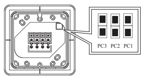
Back of SCM24W
| Tone Selection | PC3Pattern | PC2Tone | PC1Volume | |
| Jumper |  | Non- Temporal | 2700 Hz | High |
 | Temporal | 2400 Hz | Low | |
| Sound Output Dispersion | Horizontal (dB) | Vertical (dB) | |
| DEGREES | +90 | -6 | -3 |
| +60 | -2 | -2 | |
| +30 | -1 | -1 | |
| 0 | 0 | 0 | |
| -30 | -1 | -3 | |
| -60 | -2 | -5 | |
| -90 | -6 | -6 | |
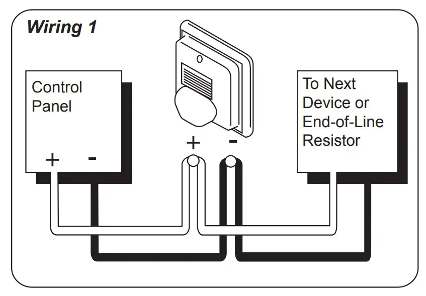
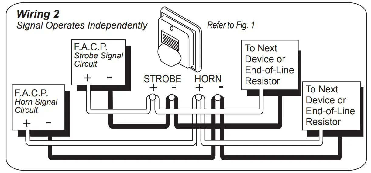
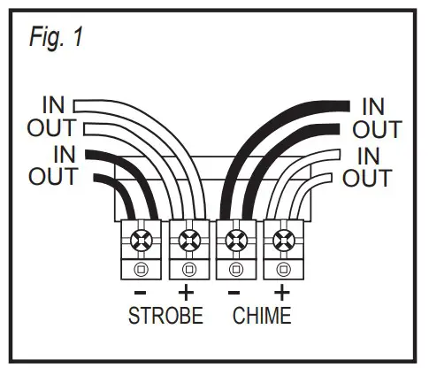
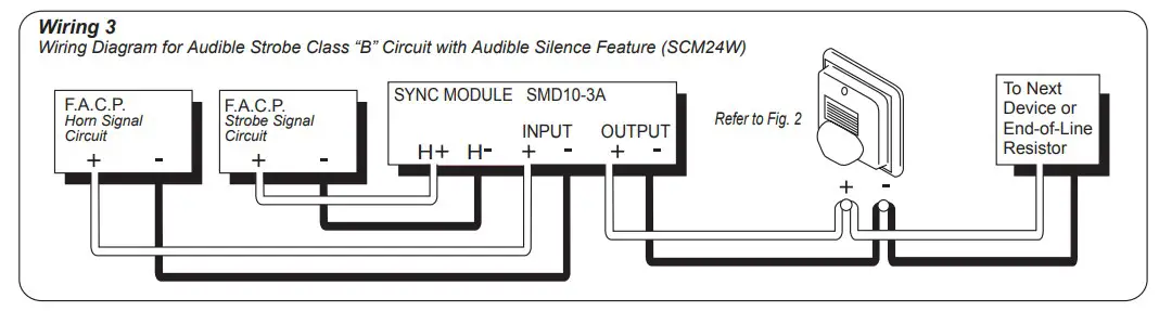
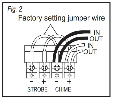
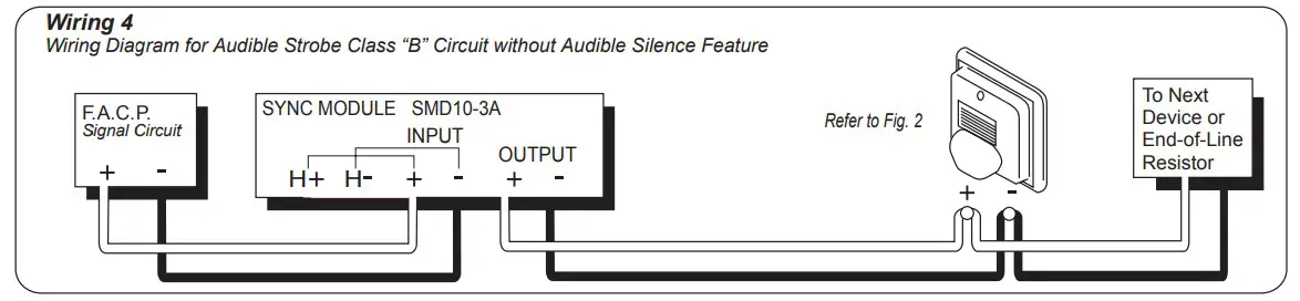
Wiring Diagram
Specifications
| Strobe Horn Current Draw Table | PC3: Pattern PC2: Tone PC1: Volume | Maximum RMS Operating Current (mA) | Minimum Sound Output (dBA @ 10ft per UL464) | ||||||
| PC3 | PC2 | PC1 | Regulated 24VDC | Regulated 24V FWR | Regulated 24VDC | ||||
| Chime and Strobe (15cd) | Non-Temp | 2700 Hz | High | 1 | 1 | 1 | 112 | 155 | 66 |
| Low | 1 | 1 | 0 | 109 | 153 | 61 | |||
| 2400 Hz | High | 1 | 0 | 1 | 111 | 155 | 54 | ||
| Low | 1 | 0 | 0 | 109 | 153 | 50 | |||
| Temporal | 2700 Hz | High | 0 | 1 | 1 | 112 | 155 | 65 | |
| Low | 0 | 1 | 0 | 109 | 153 | 60 | |||
| 2400 Hz | High | 0 | 0 | 1 | 111 | 155 | 53 | ||
| Low | 0 | 0 | 0 | 109 | 153 | 48 | |||
| Chime and Strobe (30cd) | Non-Temp | 2700 Hz | High | 1 | 1 | 1 | 155 | 217 | 66 |
| Low | 1 | 1 | 0 | 152 | 215 | 61 | |||
| 2400 Hz | High | 1 | 0 | 1 | 154 | 217 | 54 | ||
| Low | 1 | 0 | 0 | 152 | 215 | 50 | |||
| Temporal | 2700 Hz | High | 0 | 1 | 1 | 155 | 217 | 65 | |
| Low | 0 | 1 | 0 | 152 | 215 | 60 | |||
| 2400 Hz | High | 0 | 0 | 1 | 154 | 217 | 53 | ||
| Low | 0 | 0 | 0 | 152 | 215 | 48 | |||
| Chime Only | Non-Temp | 2700 Hz | High | 1 | 1 | 1 | 45 | 58 | 66 |
| Low | 1 | 1 | 0 | 40 | 52 | 61 | |||
| 2400 Hz | High | 1 | 0 | 1 | 44 | 57 | 54 | ||
| Low | 1 | 0 | 0 | 40 | 52 | 50 | |||
| Temporal | 2700 Hz | High | 0 | 1 | 1 | 45 | 58 | 65 | |
| Low | 0 | 1 | 0 | 40 | 52 | 60 | |||
| 2400 Hz | High | 0 | 0 | 1 | 44 | 57 | 53 | ||
| Low | 0 | 0 | 0 | 40 | 52 | 48 | |||
Installation Options