
NOTIFIER CHSCRL Selectable Output Chimes and Chime or Strobes
Audio/Visual Devices
General
System Sensor L-Series selectable-output chimes and chime/strobes are rich with features guaranteed to cut installation times and maximize profits with lower current draw and mod-ern aesthetics.
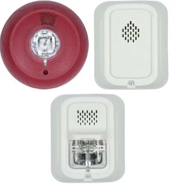
The System Sensor L-Series product line of wall and ceiling-mount chimes and chime strobes include a variety of features that increase their application versatility while simplifying the installation. With white and red plastic housings, System Sen-sor L-Series can meet virtually any application requirement.
Selectable-output chimes and chime/strobes are private mode notification appliances used to alert trained personnel to inves-tigate possible emergency situations and to take appropriate action. Security guard and nurse workstations are ideal loca-tions for chime products.
All devices feature plug-in design with minimal intrusion into the back box, making the installation fast and foolproof while virtually eliminating costly and time-consuming ground faults.
Installers can easily adapt devices to a wide range of applica-tion requirements using field-selectable candela settings, auto-matic selection of 12-or-24 volt operation, and a rotary switch for chime tones and two volume selections.
Features
- Updated modern aesthetics
- Plug-in design with minimal intrusion into the back box
- Mounting plate shorting spring feature checks wiring conti-nuity before device installation
- Captive mounting screw
- Tamper-resistant construction
- Field-selectable candela settings:
- Wall: 15, 30, 75, 95, 110, 135, 185
- Ceiling: 15, 30, 75, 95, 115, 150, 177
- Automatic selection of 12- or 24-volt operation at 15 and 30 candela
- Rotary switch for tone and volume selections
- Five selectable tones with high and low volume settings
- Electrically compatible with legacy SpectrAlert and SpectrAlert Advance devices
- Wall models listed for wall mounting only, ceiling models listed for ceiling mounting only
- UL 1638 listed
Architect/Engineer Specifications
GENERAL
System Sensor L-Series chimes and chime strobes shall mount to a standard 4 × 4 × 1½-inch back box, 4-inch octagon back box, single-gang 2 × 4 × 17/8-inch back box, or double-gang back box. A universal mounting plate shall be used for mounting products. The notification appliance circuit wiring shall terminate at the universal mounting plate. Also, System Sensor L-Series products, when used with the Sync•Circuit Module accessory, shall be powered from a non-coded notifi-cation appliance circuit output and shall operate on a nominal 12 or 24 volts. When used with the Sync•Circuit Module, 12-volt rated notification appliance circuit outputs shall operate between 8.5 and 17.5 volts; 24-volt rated notification appliance circuit outputs shall operate between 16.5 and 33 volts. Indoor L-Series products shall operate between 32 and 120 degrees Fahrenheit from a regulated DC, or full-wave rectified, unfil-tered power supply. Chime strobes shall have field-selectable candela settings of 15, 30, 75, 95, 110, 135, and 185 for wall units and 15, 30, 75, 95, 115, 150, and 177 for ceiling units.
CHIME STROBE COMBINATION
The chime strobe shall be a System Sensor SpectrAlert Advance Model _______ listed to UL 1638 and UL 464. The chime strobe shall comply with the Americans with Disabilities Act requirements for visible signaling appliances, flashing at 1Hz over the strobe’s entire operating voltage range. The strobe light shall consist of a xenon flash tube and associated lens/reflector system. The chime shall have two audibility options and an option to switch between temporal three pat-tern, non-temporal (continuous) pattern, 1 second chime pat-tern, 1/4 second chime pattern, 5 second whoop chime pattern. These options are set by a multiple position switch.
SYNCHRONIZATION MODULE
The module shall be a System Sensor Sync•Circuit _______ listed to UL 464 and shall be approved for fire protective ser-vice. The module shall synchronize SpectrAlert strobes at 1Hz and all available chime tones. Also, while operating the strobes, the module shall silence the chimes on chime/strobe models over a single pair of wires. The module shall mount to
a 411/16 × 4 11/16 × 21/8-inch back box. The module shall also control two Style Y (class B) circuits or one Style Z (class A) circuit. The module shall synchronize multiple zones. Daisy chaining two or more synchronization modules together will synchronize all the zones they control. The module shall not operate on a coded power supply.
PHYSICAL/ELECTRICAL SPECIFICATIONS
- Standard Operating Temperature: 32°F to 120°F (0°C to 49°C)
- Humidity Range: 10 to 93% non-condensing
- Strobe Flash Rate: 1 flash per second
- Nominal Voltage: Regulated 12VDC or regulated 24DC/FWR1
- Operating Voltage Range2: 8 to 17.5V (12V nominal) or 16 to 33V (24V nominal)
- Operating Voltage Range with MLD3: 8.5 to 17.5V (12V nominal) or 16.5 to 33V (24V nominal)
- Input terminal wire gauge: 12 to 18 AWG
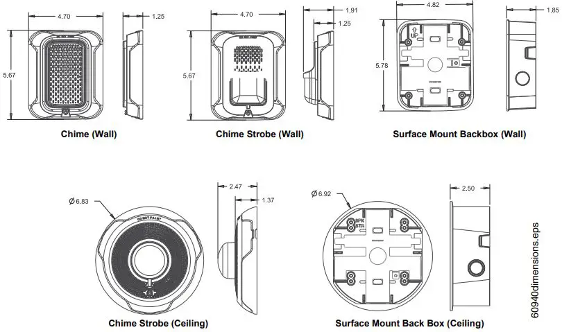
- Chime strobe dimensions (including lens): 5.6 in L × 4.7 in W × 1.25 in D (143 mm L × 119 mm W × 32 mm D)
- Chime dimensions: 5.6 in L × 4.7 in W × 1.25 in D (143 mm L × 119 mm W × 32 mm D)
- Ceiling Chime strobe dimensions (including lens): 6.8 in. Diameter x 2.47in. D (173.5mm Diameter x 62.7mm D)
- SBBRL (red wall surface mount back box): 5.6 in L × 4.7 in W × 4.3 in D (142 mm L × 119 mm W × 109 mm D)
- SBBWL (white wall surface mount back box): 5.6 in L × 4.7 in W × 4.3 in D (142 mm L × 119 mm W × 109 mm D)
- SBBCRL (red ceiling surface mount back box): 6.9 in. Dia. x 2.5in. D (175.8mm Dia. x 63.5mm)
- SBBCWL (white ceiling surface mount back box): 6.9in. Dia. x 2.5in. D (175.8mm Dia. x 63.5mm)
Notes
- Full Wave Rectified (FWR) voltage is a non-filtered, time varying power source that is used on some power supply and panel outputs.
- CHS products will operate at 12 V nominal only for 15 and 30 cd.
Tone Selection
Chime tone selection is accomplished by using the rotary switch on the back of the product.
The current draw and sound measurements for various chime tone settings are listed below.
CHIME PATTERNS
| Setting | Repetition Rate | dB Level |
| 1 | 1 Second Chime | High |
| 2 | 1 Second Chime | Low |
| 3 | ¼ Second Chime | High |
| 4 | ¼ Second Chime | Low |
| 5 | Temporal Chime | High |
| 6 | Temporal Chime | Low |
| 7 | 5 Second Whoop | High |
| 8 | 5 Second Whoop | Low |
| 9 | Coded** | High |
| **For chime only. | ||
CHIME AND CHIME/STROBE OUTPUT (DBA)
| Switch Posi- tion |
Sound Pattern |
dB | 8–17.5 Volts | 16–33 Volts | |
| DC | DC | FWR | |||
| 1 | 1 Second Chime | High | 61 | 62 | 62 |
| 2 | 1 Second Chime | Low | 56 | 55 | 55 |
| 3 | ¼ Second Chime | High | 67 | 70 | 70 |
| 4 | ¼ Second Chime | Low | 61 | 61 | 61 |
| 5 | Temporal Chime | High | 64 | 66 | 66 |
| 6 | Temporal Chime | Low | 59 | 60 | 60 |
| 7 | 5 Second Whoop | High | 76 | 78 | 78 |
| 8 | 5 Second Whoop | Low | 62 | 64 | 64 |
| 9 | Coded** | High | 57 | 51 | 57 |
| **For chime only. | |||||
UL Current Draw Data
UL MAX. CHIME CURRENT DRAW (MA RMS)
|
Sound Pattern |
dB | 8-17.5 Volts | 16-33 Volts | |
| DC | DC | FWR | ||
| 1 Second Chime | High | 5 | 8 | 9 |
| 1 Second Chime | Low | 5 | 8 | 9 |
| 1/4 Second Chime | High | 6 | 10 | 10 |
| 1/4 Second Chime | Low | 5 | 9 | 9 |
| Temporal Chime | High | 7 | 10 | 10 |
| Temporal Chime | Low | 6 | 9 | 9 |
| 5 Second Whoop | High | 12 | 15 | 16 |
| 5 Second Whoop | Low | 7 | 10 | 11 |
| Coded | High | 12 | 15 | 16 * |
| 1 Second Chime | High | 5 | 8 | 9 |
*This data represents coding at 3 chimes per second. Actual current draw will vary depending upon coding selected.
UL MAX. CHIME/STROBE CURRENT DRAW (MA RMS) WALL
| DC Input | 8–17.5 Volts | 16–33 Volts | |||||||
| 15 | 30 | 15 | 30 | 75 | 95 | 110 | 135 | 185 | |
| 1 Second Chime | 90 | 154 | 51 | 71 | 115 | 136 | 161 | 202 | 238 |
| 1 Second Chime | 89 | 154 | 50 | 70 | 116 | 136 | 154 | 199 | 242 |
| 1/4 Second Chime | 90 | 154 | 52 | 72 | 117 | 137 | 168 | 201 | 242 |
| 1/4 Second Chime | 89 | 153 | 49 | 70 | 115 | 136 | 165 | 199 | 241 |
| Temporal Chime | 88 | 153 | 49 | 69 | 112 | 137 | 168 | 201 | 246 |
| Temporal Chime | 88 | 152 | 47 | 68 | 111 | 136 | 167 | 196 | 241 |
| 5 Second Whoop | 91 | 154 | 52 | 70 | 113 | 132 | 176 | 206 | 243 |
| 5 Second Whoop | 87 | 149 | 46 | 66 | 108 | 130 | 170 | 202 | 240 |
| FWR Input | 16–33 Volts | ||||||
| 15 | 30 | 75 | 95 | 110 | 135 | 185 | |
| 1 Second Chime | 70 | 90 | 160 | 176 | 197 | 233 | 275 |
| 1 Second Chime | 67 | 88 | 158 | 175 | 191 | 232 | 271 |
| 1/4 Second Chime | 69 | 93 | 159 | 175 | 198 | 233 | 272 |
| 1/4 Second Chime | 68 | 93 | 154 | 169 | 196 | 232 | 270 |
| Temporal Chime | 65 | 90 | 145 | 170 | 189 | 228 | 283 |
| Temporal Chime | 64 | 89 | 142 | 170 | 188 | 219 | 282 |
| 5 Second Whoop | 70 | 93 | 145 | 168 | 187 | 223 | 278 |
| 5 Second Whoop | 62 | 84 | 137 | 159 | 180 | 216 | 272 |
UL MAX. CHIME/STROBE CURRENT DRAW (MA RMS) CEILING
| DC Input | 8–17.5 Volts | 16–33 Volts | |||||||
| 15 | 30 | 15 | 30 | 75 | 95 | 115 | 150 | 177 | |
| 1 Second Chime | 95.5 | 165 | 47 | 69 | 117 | 137 | 165 | 202 | 238 |
| 1 Second Chime | 93 | 162 | 47 | 68 | 116 | 137 | 165 | 200 | 238 |
| 1/4 Second Chime | 94 | 161 | 48 | 70 | 117 | 138 | 166 | 202 | 237 |
| 1/4 Second Chime | 93 | 157 | 48 | 69 | 116 | 137 | 164 | 199 | 236 |
| Temporal Chime | 93 | 163 | 48 | 69.5 | 116 | 138 | 165 | 199 | 238 |
| Temporal Chime | 92 | 160 | 47 | 68.5 | 116 | 136 | 164 | 198 | 237 |
| 5 Second Whoop | 98 | 169 | 54 | 77 | 124 | 146 | 173 | 206 | 245 |
| 5 Second Whoop | 95 | 166 | 49 | 71 | 117 | 144 | 168 | 202 | 239 |
| FWR Input | 16–33 Volts | ||||||
| 15 | 30 | 75 | 95 | 115 | 150 | 177 | |
| 1 Second Chime | 63 | 90 | 147 | 169 | 184 | 212 | 245 |
| 1 Second Chime | 63 | 88 | 147 | 169 | 183 | 212 | 244 |
| 1/4 Second Chime | 65 | 90 | 149 | 170 | 184 | 213 | 246 |
| 1/4 Second Chime | 64 | 89 | 148 | 168 | 184 | 213 | 244 |
| Temporal Chime | 64 | 89 | 148 | 169 | 184 | 212 | 245 |
| Temporal Chime | 63 | 88 | 147 | 169 | 183 | 212 | 245 |
| 5 Second Whoop | 75 | 100 | 155 | 178 | 193 | 221 | 255 |
| 5 Second Whoop | 68 | 91 | 148 | 170 | 186 | 217 | 248 |
Product Drawings: Dimensions
Agency Listings and Approvals
The listings and approvals below apply to L-series devices. In some cases, certain modules or applications may not be listed by certain approval agencies, or listing may be in process. Consult factory for latest listing status.
- UL/ULC Listed: S4011
- FM Approved
Product Line Information
Note: ULC-listed devices include required French labeling. See Agency Listings for listing details.
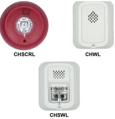
- CHWL, CHRL. Chime, Wall (White, Red).
- CHSWL(A), CHSRL(A). Chime Strobe, Wall (White, Red). CHSCWL, CHSCRL. Chime Strobe, Ceiling (White, Red).
ACCESSORIES
- SBBWL, SBBRL. Surface Mount Back Box, Wall (White, Red).
- SBBCWL, SBBCRL. Surface Mount Back Box, Ceiling.(White, Red).


