EATON PSS55A Cutler-Hammer Power Supply Switcher Instruction Manual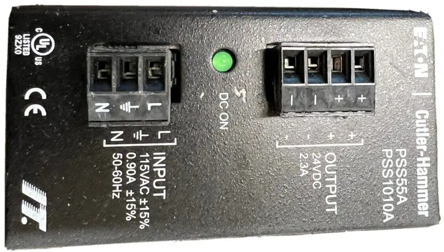
Installation
The PROFIBUS module is designed to be used in industrial applications and installed in accordance with this document.
Mount the Module
To mount the PROFIBUS adapter to Motor Insight® or C440-COM-ADP the following proceedure must be preformed.
- Place the tabs opposite the PROFIBUS connector into the lower slots provided on the Motor Insights right side.
- Pivot the module on the lower tabs toward the Motor Insight.
- Gently press the module and Motor Insight together.
Connect the PROFIBUS Adapter to PROFIBUS Connect the PROFIBUS terminal to the PROFIBUS DB9 connector located on the side of the module. The connector has screws for positive retention to eliminate accidental unplugging.
Connect 24 Vdc control power to the 5-position header.
- The connector has screws for positive retention to eliminate accidential unplugging.
- Use one wire per terminal.
Set the PROFIBUS address
The PROFIBUS address is set using the DIP switches located on the face of the module. The PROFIBUS address is binary with the major units numbered to the left of the switch on the side label. Adding up the major units set to ON determines the address of the module.
Example: To set the address to 25, start from the switch mark 32 and set the switches to Off (32), ON (16), ON (8), OFF (4), OFF (2) ON (1) (16+8+1 =25).
Note: Address is only updated upon power up.
The PROFIBUS baud rate is set automatically using an auto baud technology, there is no need to set the baud rate. For more information on the PROFIBUS attributes and how to modify them, refer to the appropriate user manual. Motor Insight MN04209001E, C440 MN04201001E or S611 MN03902011E.
The GSD file is located on the Eaton web site, go to www.eaton.com.
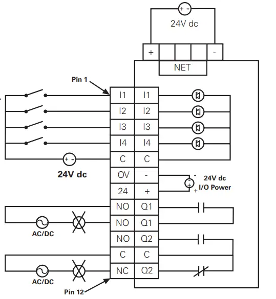
C441S – 120 Vac Input Specification
Example: 120V ac 10 Module
- All inputs are isolated.
- All common terminals are connected together internally.

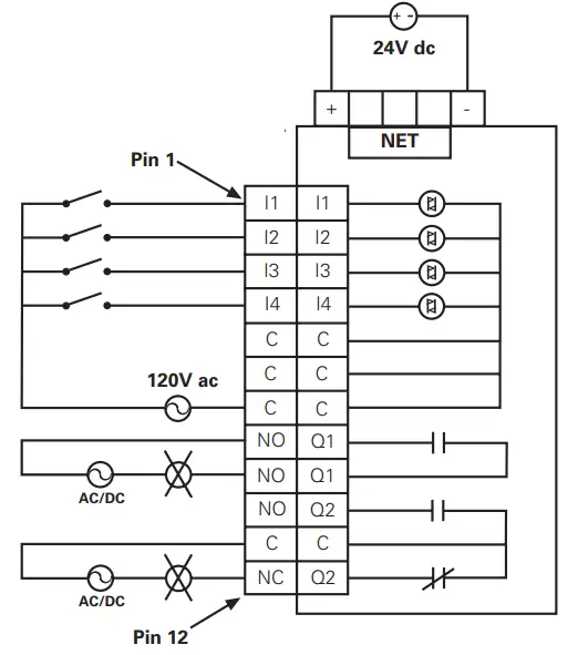
| Specification | Value |
| Number of Inputs | 4 |
| Nominal Voltage | 120 Vac |
| Nominal Current | 15mA |
| Operating Frequency | 50/60Hz |
| Signal Delay max. | 30ms |
| Input type | IEC 61131-2Type 1 Digital |
C441Q – 24 Vdc Input Specification
Example: Non Isolating 24V dc input Source
- Input source power is taken from 5 pin connector.
- Connect C and OV together.
- Use 24 to source Inputs.

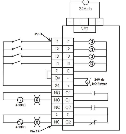
Example: Isolated 24V dc Input Source
- The inputs must be supplied by an external power source.
- Do not connect the external supply to terminals OV and 24.
- connect isolated power source Pin between C and inputs.

Installation Leaflet IL04209006E Effective July 2010
| Specification | Value |
| Number of Inputs | 4 |
| Nominal Voltage | 24 Vdc |
| Nominal Current | 5mA |
| Type | Current Sinking |
| Input Type | IEC 61131-2, Type 1 Digital |
| Max 24 Vdc Source Current | 50mA |
PROFIBUS Adapter Setup and Configuration
Configure C441 Profibus Adapter
- Load the gsd file for the C441 Profibus Adapter into the Master’s
configuration tool. - Select and add the C441 Profibus Adapter to the network configuration.
- The default configuration for the C441 Profibus Adapter is a
StandAlone IO base. If the C441 Profibus Adapter is to connect
to a base device; remove the modules from all 28 slots of the default configuration. - Select and add the attached device’s base module to slot 1 of the C441 Profibus Adapter configuration. NOTE: The appropriate base module MUST be placed in slot 1 of the configuration. Failure to do so will cause configuration to fail.
- Select and add the desired modules for the data exchange into slots 2- 28. Select only those modules supported by the base module (See the base device’s user manual for a list of supported modules)
Example Configuration
| I/O module | Type | Description |
| C441 MotorInsight Base | base – no IO | Attached Device |
| Com Adapter Outputs | output – 1 byte | Controls C441 adapter outputs |
| MI Command Register | output – 2 bytes | Controls MI Relay- start/stop |
| Com Adapter Inputs | input – 1 byte | Status of C441 adapt- er inputs |
| MI RMS Current Ave | input – 2 bytes | Average rms current reading |
| MI RMS Voltage Ave | input – 2 bytes | Average rms voltage reading |
| MI Total Kilowatts | input – 2 bytes | Total power reading |
Setup C441 Profibus Adapter Device Parameters
- Select the C441 Profibus Adapter to display its device parameters.
- Set the “Enable Device Parameters & Adapter Outputs ComLos
Behavior” parameters.
Note: To enable writing of the device parameters into the attached
base device “Enable Device Parameters” must be set to “Download Device Parameters”.
Setup the Device Parameters
- Select the base module in the configuration to display its device
parameters. The base module contains the parameters to enable/disable faults, set thresholds, etc. for the attached device.
Example: The following parameters can be found in C441 MotorInsight Base Module
- CT Multiplier
- Overload FLA
- Overload Trip Class
- GND Fault Trip Level
- Low KW Trip Level
- High KW Trip Level
- Under Voltage Trip Level
- Over Voltage Trip Level
After all configuration is complete, save and download the new configuration settings to the Master(PLC) & C441 Profibus Adapter.
Profibus Diagnostics
The C441 Profibus Adapter provides the user with status information
along with fault and warning data relevant to the operation of the attached base module. Fault and warning information is presented to the user through extended diagnostics. All fault information is sent to the Master as high priority diagnostic messages (ext. diag. bit set in diagnostic message). All warning information is sent as low priority diagnostic messages (ext diag. bit clear). Low priority diagnostic messages are issued as the fault condition clears. See the User Manual for the attached base module’s diagnostic message bit definitions
Environmental Ratings of the Module
| Transportation and Storage | Temperature | -40ºC to 85ºC (-40ºF to 185ºF) |
| Humidity | 5 – 95 % non-condensing | |
| Operating | Temperature | -20ºC to 50ºC (-4ºF to 122ºF) |
| Humidity | 5 – 95 % non-condensing | |
| Altitude | Above 2000meters (6600feet)consult factory | |
| ShockICE 60068-2-27 | 15G any direction for11 milliseconds | |
| VibrationIEC 60068-2-6 | 3G in any direction | |
| Polution Degree | 3 |
Approvals / Certifications
| Electrical / EMC | |
| ESD Immunity | +/- 8kV air, +/- 4kV contact |
| Radiated Immunity (IEC61000-4-3) | 10V/m 80-1000 MHz, 80%amplitude modulation @ 1kHz |
| Fast Transient (IEC61000-4-4) | +/- 2kV communications |
| Surge (IEC61000-4-5) | +/- 2kV shield-to-ground |
| RF Conducted (IEC610000-4-6) | 10V, 0.15 – 80MHz |
| Ingress Protection Code | IP20 |
| Radiated and Conducted Emissions | EN55011 (CISPR 11) Class A |
| Agency Certifications | UL® 508cUL® (CSA C22.2 No. 14)CE (Low Voltage Directive) PROFIBUS Certification RoHS |
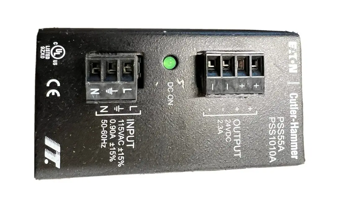
Module Electrical Requirements
Notes For use with Eaton UL Listed Power Supply Catalog Nos. PSS55A, PSS55B, PSS55C, or PS160E.
Any UL Listed isolated power supply with a maximum of 30 Vdc
output may be used, provided that a UL Listed or Recognized Fuse rated no more than 3A maximum be installed.
5pin 24 VDC Power, RS485 Connector
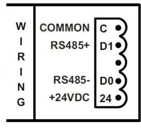
CURRENT DRAW: 30mA TERMINAL TORQUE: .25 Nm (2.25 lb-in)


