![]() ABL 8RPS24pp0 / 8RPM24200 / 8WPS24p00
ABL 8RPS24pp0 / 8RPM24200 / 8WPS24p00
Instruction Manual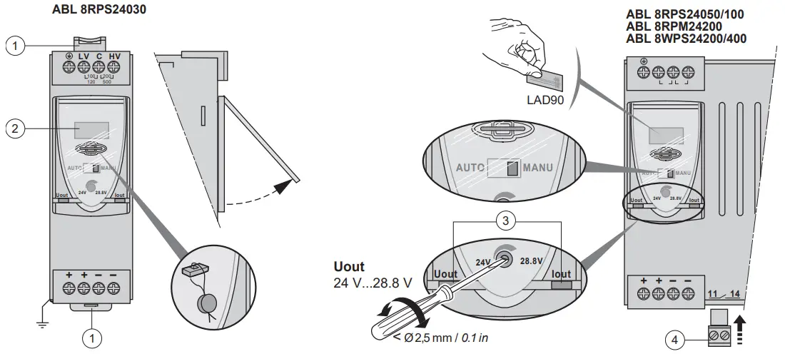
8RPM24200 Regulated Switch Power Supply
1 – 35 mm DIN rail mounting clip.
2 – Snap-on label.
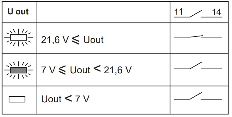
3 – Voltage and output current. status LED Uout – Iout.
4 – Diagnostic Output (Normally Open dry contact 11-14)
| U In | I out | ABL | U In | I out | ABL | ||
| 1 Ph ~ 100…120 V | 3 A | 8RPS24030 | 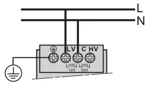 | 1 Ph ~200…500 V | 3 A | 8RPS24030 | 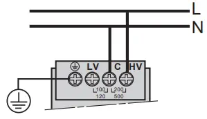 |
| 5 A | 8RPS24050 | 5 A | 8RPS24050 | ||||
| 10 A | 8RPS24100 | 10 A | 8RPS24100 | ||||
| 1 Ph ~ 100…120 V | 20 A | 8RPM24200 | 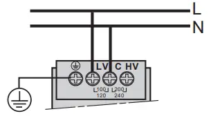 | 1 Ph ~ 200…240 V | 20 A | 8RPM24200 | 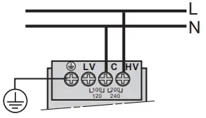 |
| 2 Ph ~ 0200…500 V | 3 A | 8RPS24030 | 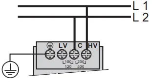 | 3 Ph ~ 380…500 V | 20 A | 8WPS24200 | 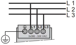 |
| 5 A | 8RPS24050 | 40 A | 8WPS24400 | ||||
| 10 A | 8RPS24100 | ||||||
![]() DANGER
DANGER
HAZARD OF ELECTRIC SHOCK, EXPLOSION OR ARC FLASH
Disconnect all power before servicing equipment.
Failure to follow these instructions will result in death or serious injury.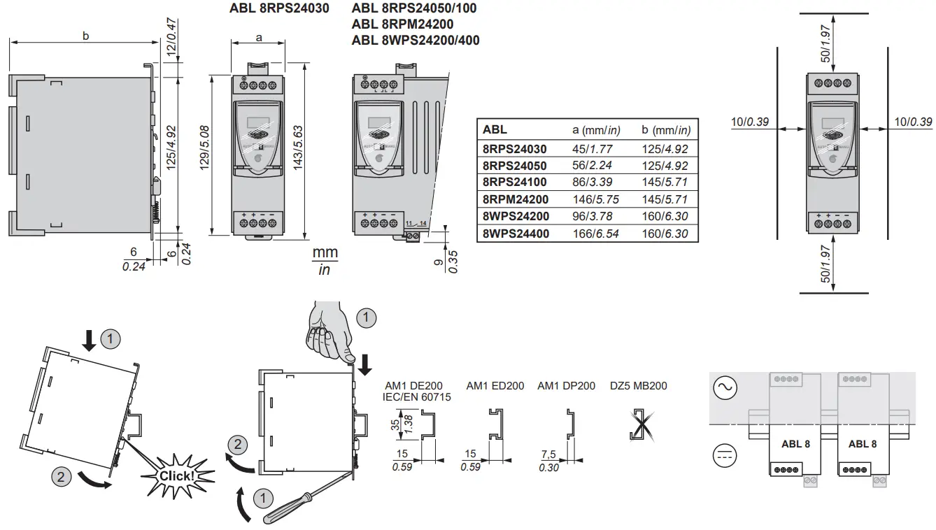
| OFF | |
| Green | |
| Orange | |
| Red |
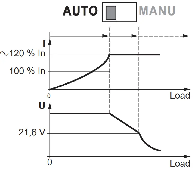
AUTO
Constant current mode. Return to rated power supply operation once the source of overcurrent has been corrected.
| I out | |
| Iout ≤ In | |
| Iout > In | |
| 0 V / 0 A Power deactivated after detection of overcurrent, overvoltage or overtemperature. (1) 0V/0A |
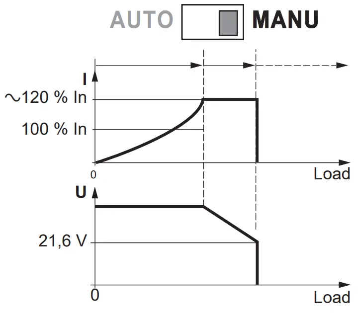
MANU
Error retention. Following deactivation, remove power to the primary circuit and reapply power to the product again.
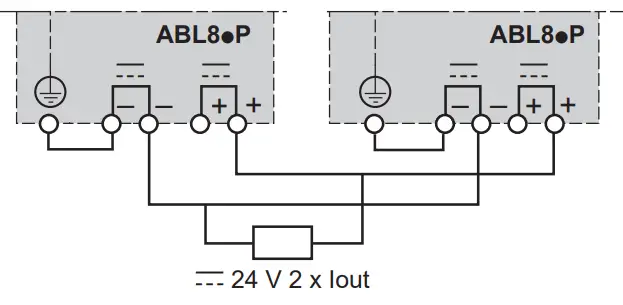
![]() 2 ABL 8pP max output //
2 ABL 8pP max output //
SELV / TBTS
Outputs connected in parallel
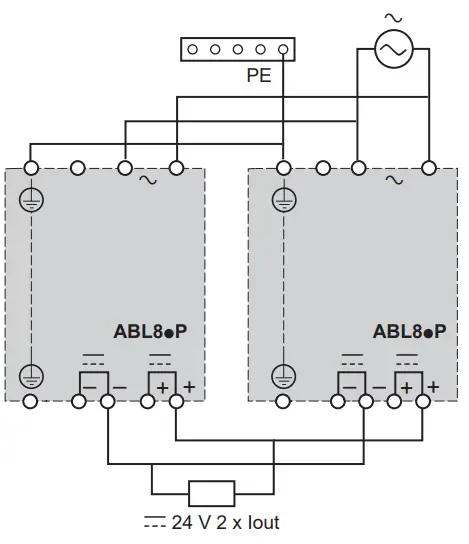
SELV: Safety Extra Low Voltage
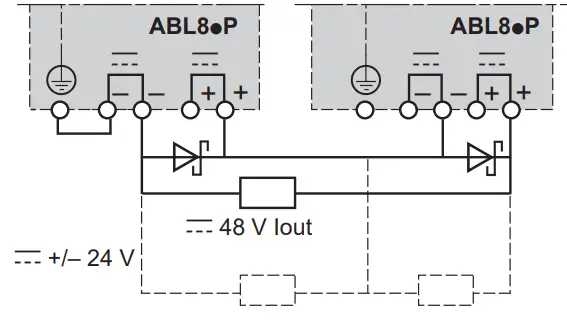
![]() 2 ABL 8pP max output …..
2 ABL 8pP max output …..
SELV / TBTS
Series connection of the power supplies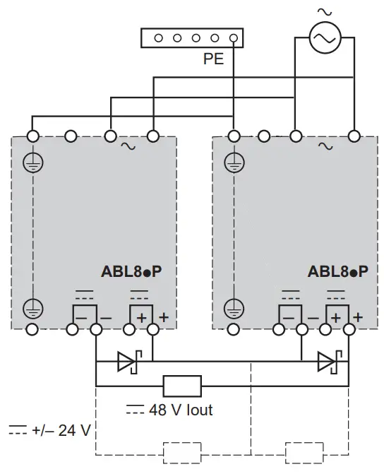
PELV / TBTP
PELV / TBTP :
PELV: Protection Extra Low Voltage
Paralleling:
– Use maximum of 2 power supplies of the same reference.
PELV / TBTP
![]() WARNING
WARNING
RISK OF MATERIAL DAMAGE AND HOT ENCLOSURE
– Allow the product sufficient time to cool before touching.
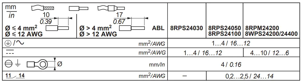
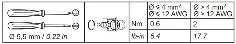
– Follow proper mounting instructions including torque values and the crimping lengths on wire terminations.
– Do not allow liquids or foreign objects to enter this product.
Failure to follow this instruction can result in death, serious injury, or equipment damage.
Environment characteristics
Installation in a pollution degree 2 environment.
Maximum surrounding air temperature 50 °C (122 °F).
Minimum temperature rating of the conductor wires connected to the terminals : 75 °C (167 °F).
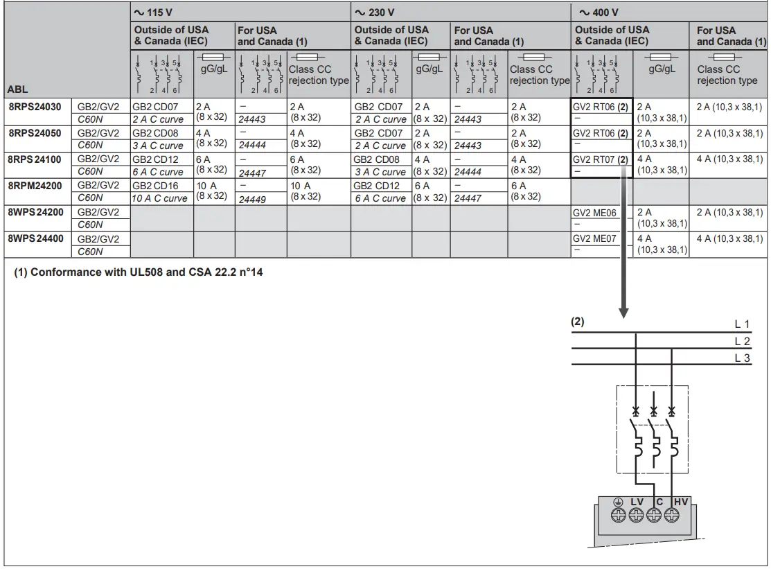
Selection of the protections on the power supply primary circuit
To be ordered separately
 www.schneider-electric.com
W9 1489414 01 11 A05
07 – 2017