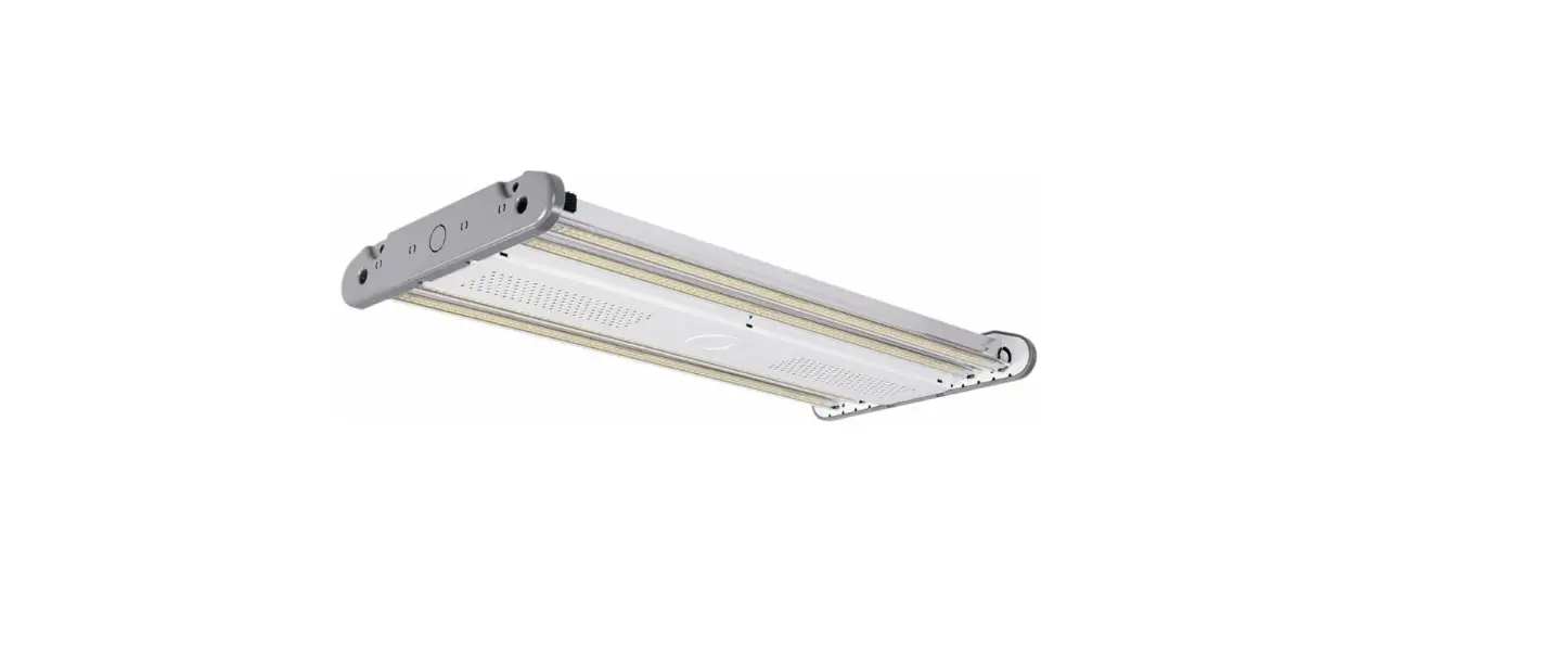
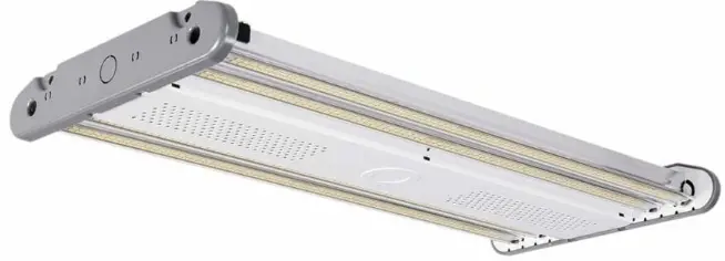
Linmore LED AH1 Ace LED High Bay
INSTRUCTION
READ CAREFULLY BEFORE INSTALLING THE FIXTURE. PLEASE KEEP THIS MANUAL FOR FUTURE USE.
- Fixtures must be installed and wired in accordance with the National Electrical Code (NEC) and all applicable local codes by a person familiar with the construction and operation of the product and hazards involved.
- Proper grounding is required for safety.
- Check that voltage is compatible with fixture driver, use approved connectors for all electrical connections.
- Be cautious of any sharp edges. Wear proper PPE (personal protected equipment) while handling.
- Fixture not suitable for use in wet locations, corrosive environments, and with thermal insulation.
WARNING: Risk of Fire or Electric Shock
- Risk of fire or electric shock. Make sure power is off at the circuit breaker before installing or maintaining the product.
- To prevent wiring damage or abrasion, do not expose wiring to edges of sheet metal or other sharp objects.
- Installation guide requires knowledge of luminaire electrical systems. If not qualified, do not attempt installation. Contact a qualified electrician.
- Never perform maintenance or cleaning while fixture is energized. Disconnect power and allow fixture to cool off before maintaining.
MAINTENANCE CAUTION
- Review the diagrams before beginning and make sure the fixture is grounded properly.
- For lighting controls, use driver wiring diagram. Maintenance must be done by qualified electricians. Use a clean, dry cloth to clean the fixture.
- For any questions regarding wiring, installation, or use of this fixture, please call 559-485-6010 or email [email protected]
TECHNICAL SPECS
| AH10S-A2-12K-SM-50-80-FR-LV-CRM-S-10V | SM | 85 |
AC 120-277V |
≥0.9 |
5000K |
≥80 |
0-10V |
5 Years |
| AH10S-A2-15K-SM-50-80-FR-LV-CRM-S-10V | SM | 110 | ||||||
| AH10S-A2-18K-SM-50-80-FR-LV-CRM-S-10V | SM | 130 | ||||||
| AH10S-A2-24K-MD-50-80-FR-LV-CRM-S-10V | MD | 165 | ||||||
| AH10S-A2-30K-MD-50-80-FR-LV-CRM-S-10V | MD | 220 | ||||||
| AH10S-A2-40K-LG-50-80-FR-LV-CRM-S-10V | LG | 295 | ||||||
| AH10S-A2-48K-LG-50-80-FR-LV-CRM-S-10V | LG | 320 |
Dimensions


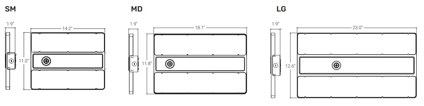
| 14.2 | 11.0 | 1.9 | ~4 |
| 18.1 | 11.8 | 1.9 | ~6 |
| 23.0 | 12.6 | 1.9 | ~8 |
WIRING
Cautions
- Fixtures must be wired in accordance with the National Electrical Code (NEC) and all applicable local codes.
- Make sure power is off at the circuit breaker before installation or maintenance.
- Proper grounding is required to ensure safety.
Notes: Must use appropriate strain relief in accordance with local code when connecting power cord to junction box.
NORMAL POWER WIRING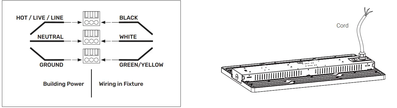
DIMMING WIRING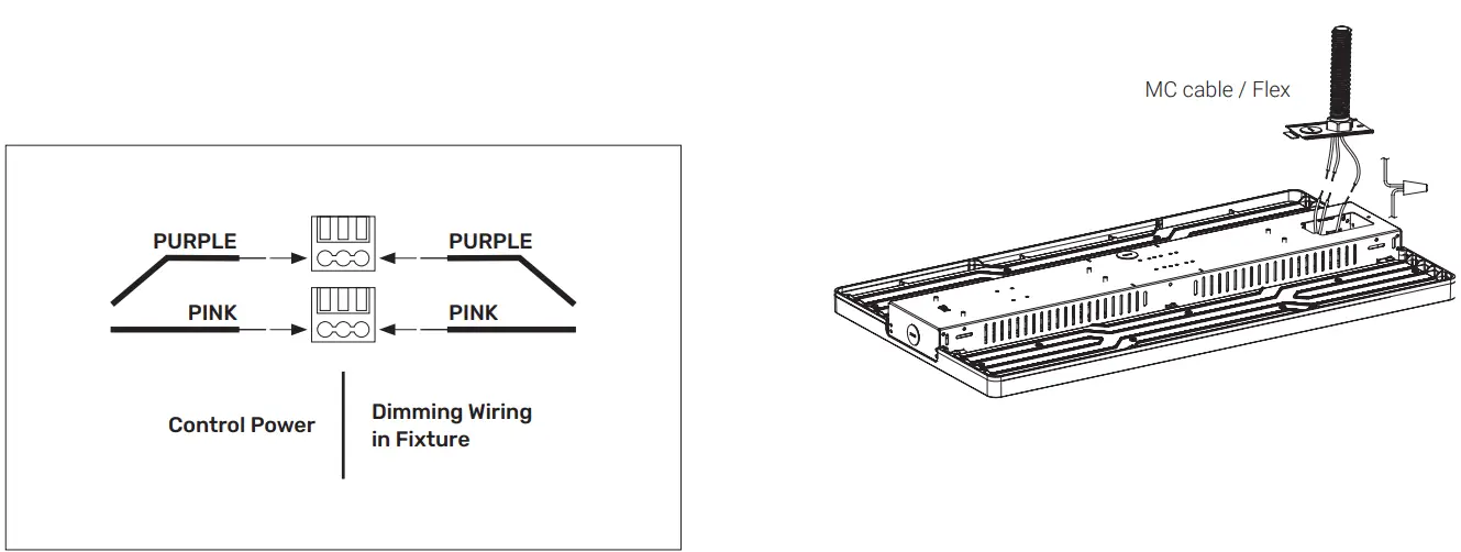
INSTALLATION GUIDE
Suspension Mounting
- Securely fasten the chain or cable to the ceiling / building infrastructure.
- Securely fasten the chain or cable to the provided V-clips.
Chain
Included in the fixture (standard).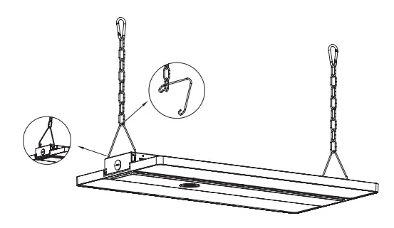
Cable
Sold separately as an accessory (CABLEKIT).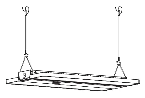
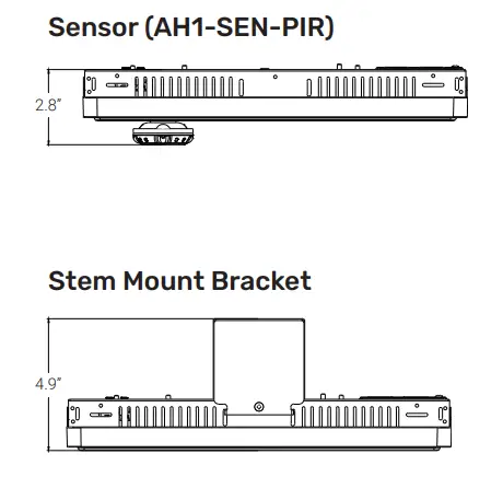
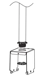
Stem Mounting (3/4” Conduit Installation)
Requires bracket sold separately as an accessory (AH1-STEM).
- Mount bracket to 3/4” existing conduit.

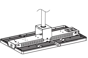
- Attach fixture to the bracket.
- Connect the wires.

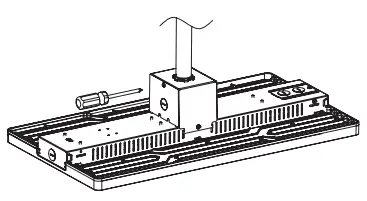
- Lock side brackets with screwdriver.

ACCESSOR
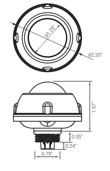
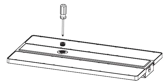
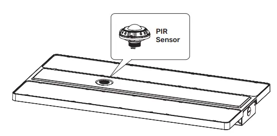
PIR Occupancy Sensor
- Use a screwdriver to remove the 1/2” plug from the sensor.

- Rotate sensor clockwise into socket and ensure contact is made. Do not over tighten. Set programming using remote control.

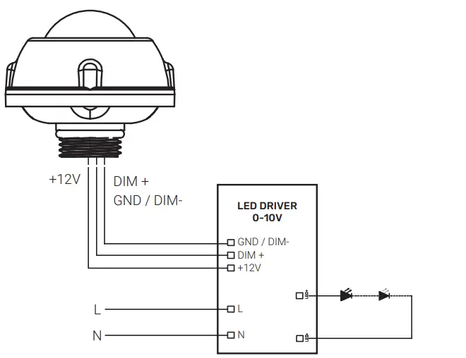
Wiring Diagram
| Default Brightness | 100% |
| Hold Time | 10 min |
| Stand-by Dimming Level | 20% |
| Stand-by Time | 30 min |
Linmore LED Labs, Inc. | 2360 S Orange Ave, Fresno CA 93725 | 559-485-6010 | linmoreled.com | [email protected]
 Instruction Manual")


