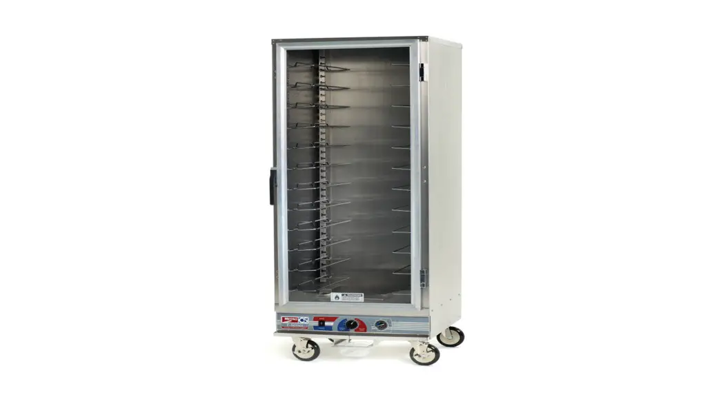
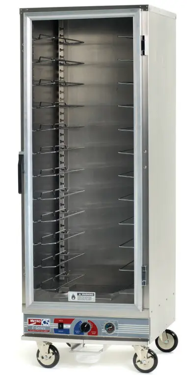
![]() C5E9-CFC-U C5 E-SERIES Heated Holding and Proofing Cabinets
C5E9-CFC-U C5 E-SERIES Heated Holding and Proofing Cabinets
Instruction Manual
Metro Heated Cabinets are for
Hot Food Holding applications only.
SAFETY INFORMATION
WARNING: Follow all food safety guidelines. Preheat the cabinet to the desired temperature before placing cooked, hot food into the cabinet. This is not a re-thermalizing cabinet. Food must be at the appropriate temperature before being placed into this cabinet. Use a food probe to check internal food temperature — the cabinet temperature is not necessarily the internal food temperature.
WARNING: Only factory-approved service agents should attempt to service, repair, or replace electrical components, wiring, or power cord.
WARNING: Unplug the cabinet before cleaning or servicing. Do not wash the cabinet with a water jet or high-pressure water.
WARNING: This cabinet is for hot food-holding applications only.
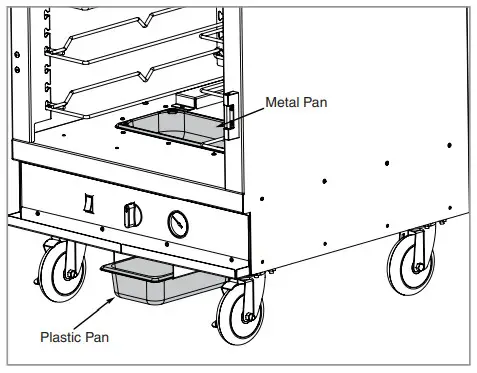
CAUTION: Stainless steel water pan and Plastic drip pan should not go together when operating the cabinet.
The stainless steel water pan is located/installed inside the cabinet and a plastic drip pan is located/installed underneath the cabinet.
CAUTION: Do not spray or pour water into the module. To clean the cabinet, wipe with a damp cloth and dry with a towel. Use only cleaning agents approved for Aluminum.
CAUTION: Water dripping onto the floor from open doors can be a slip hazard.
![]()
IDENTIFYING YOUR CABINET
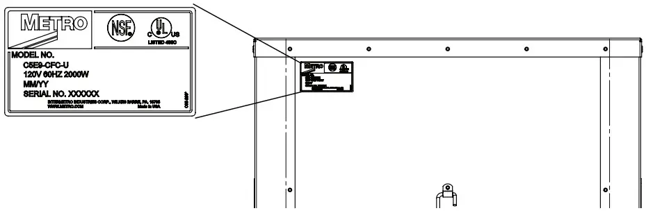
For future reference, note the serial and model number found on the data plate of the cabinet here:
Serial number ________________________________
PART NUMBERING
C5E9-CFC-U (120V, 60Hz, 2000W)
C5E9-CXFC-U (220-240V, 50/60Hz, 1681-2000W)
INSTALLATION AND SETUP
- Check the packaging and cabinet for shipping damage after unloading the unit, and after removing all the packaging.
- The receiver of this product is responsible for filing freight damage claims. This equipment must be opened immediately for an inspection. All visible damage must be reported to the freight company within 48 hours and must be noted on the freight bill at the time of delivery.
- Concealed damage is your responsibility — you must advise the carrier of any loss or damage within 15 days after receipt of the cabinet. If there is damage, retain the original packaging for inspectors.
- Any protective covers (plastic or paper sheet) must also be removed before turning the cabinet on.
- Make sure the stainless steel water pan is installed inside the cabinet in the floor opening on top of the proofing element.
- Install the plastic drip pan under the drip trough at the base of the cabinet.

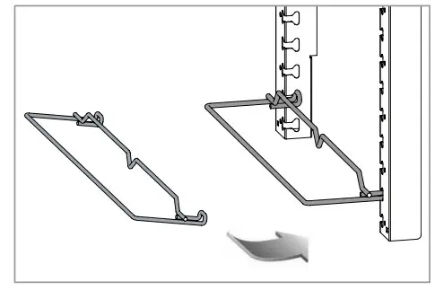
- Install the universal slides into the notches that are built into the walls as shown. The notches are spaced at 1.5” intervals, each cabinet is Metal Pan supplied with 12 sets of slides, if additional slides are desired please order part number C5-USLIDEPR-C (which is 1 additional set of slides).

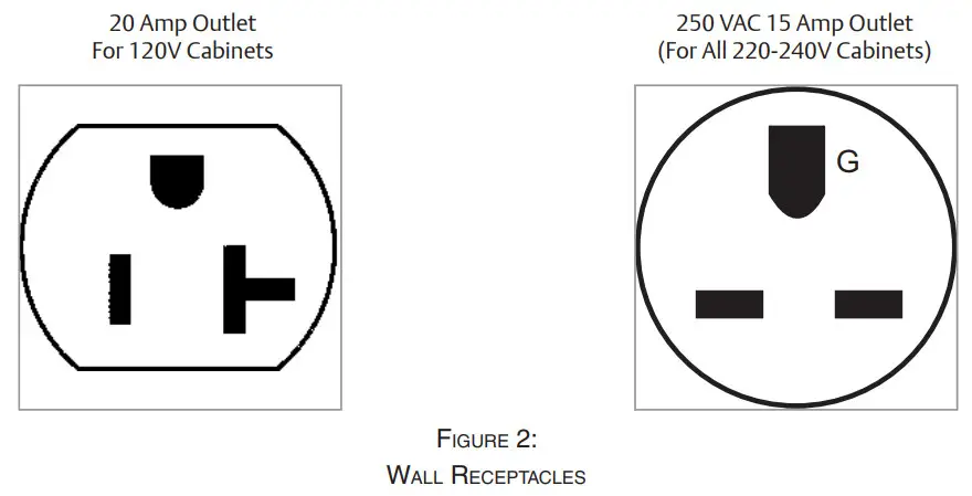
- Refer to the data plate located near the power cord for the electrical specifications of the cabinet as shown on Page 2.
• With the POWER switch OFF, plug the cord into the appropriate rated, grounded receptacle.
• Cabinets rated at 120 V must be plugged into a 20 amp 125 VAC receptacle.
• Cabinets rated at 220-240 V must be plugged into a 15 amp 250 V receptacle.
WARNING: Do not allow combustible materials to be stored or accumulate on, under, or next to the cabinet. Do not block any ventilation louvers or slots.
OPERATING INSTRUCTIONS
- Fill the stainless pan with water if proofing, or if you desire a small amount of passive humidity while in heated holding mode.
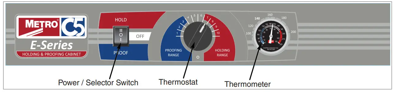
- Your cabinet has a 3-way power/selector switch that powers the cabinet on and off and also allows dual functionality. For heated holding mode set the switch to “hold” (up); for proofing mode set it to “proof” (down); to power, the unit down set it to “off” (middle).
- Heated holding mode (selector switch set to “hold”)
• Set thermostat at desired setting in red holding range, number 7 is approximately 150°F (66°C), and 10 is approximately 190°F (88°C).
• Monitor temperature read-out on the thermometer and adjust the thermostat to fine-tune as necessary. - Proofing mode (selector switch set to “proof”)
• Set thermostat at desired setting in blue proofing range. Approximate temperature yields are below, each yields a pre-determined humidity level.
– Number 1 is approximately 85°F (30°C)
– Number 2 is approximately 95°F (35°C)
– Number 3 is approximately 105°F (41°C)
• Monitor temperature read-out on the thermometer and adjust the thermostat to fine-tune as necessary.
Note: When the switch is set to hold or proof, the fan is always energized. In order to power off the fan and the unit, set the switch to “off” (middle).
CARE AND MAINTENANCE
![]() Before proceeding with any maintenance activity strictly follow “Safety Information” on page 2 of this manual.
Before proceeding with any maintenance activity strictly follow “Safety Information” on page 2 of this manual.
Cleaning The Cabinet
WARNING: Unplug the cabinet before cleaning or servicing. Do not wash the cabinet with a water jet or high-pressure water.
CAUTION: Do not spray or pour water into the control enclosure. To clean the cabinet, wipe with a damp cloth and dry with a towel. Use only cleaning agents approved for Aluminum.
CAUTION: Do not use cleaners with chlorides or phosphates as they may cause damage to Stainless Steel & Aluminum.
- Make certain that the cabinet has cooled down before cleaning. Use cleaners in proper concentrations. Follow the manufacturer’s directions for the cleaning product used. After using any cleaning products, thoroughly rinse all surfaces to remove residue.
- Use a damp cloth or sponge. Mild soap suitable for Aluminum is acceptable. Dry with a clean towel. Wipe up spills as soon as possible and regularly clean the cabinet to avoid staining and difficult-to-clean conditions.
Cabinet Maintenance — All Models
Keeping the casters free of dirt build-up will go a long way in prolonging their life. Additionally, periodic tightening of the door latch and hinge screws may be required.
![]() Regularly inspect the casters. Tighten loose fasteners and replace worn or damaged parts with new InterMetro-approved parts. Replace worn or damaged casters immediately. Additionally, periodic tightening of the door latch and hinge screws may be required.
Regularly inspect the casters. Tighten loose fasteners and replace worn or damaged parts with new InterMetro-approved parts. Replace worn or damaged casters immediately. Additionally, periodic tightening of the door latch and hinge screws may be required.
BASIC TROUBLESHOOTING
WARNING: Only factory-approved service agents must attempt to service, repair, or replace electrical components, wiring, or power cord.
1. Controls do not work (no heat being generated or fan does not run):
- Check that the cabinet is plugged-in.
- Check that the outlet has power.
- Check that the power switch is in the “On” position.
- Check the cabinet wiring from the power cord to the power switch and to the thermostat.
- For holding, make sure in HOLD mode. For proofing, make sure in PROOF mode.
2. Temperature too hot:
a. During initial pre-heat, the cabinet may overshoot the set point.
b. If the displayed temperature exceeds 220°F (104°C):
- The blower wiring is faulty or disconnected. The blower needs replacing.
- The thermostat may have failed and the thermal cut-out device is controlling the temperature.
- The thermal cut-out device may have failed.
3. Temperature too low:
a. The cabinet may still be in pre-heat or recovering from the door being opened.
b. Door is not closed or sealing properly.
c. Worn outdoor gasket. Replace gasket.
d. Blower is not circulating air:
◦ Blower wiring is faulty or disconnected.
4. No heat generated
When power is on and in HOLD mode, the amp draw for 120V units should be approximately 16 amps and 8 amps for 220-240V models. In PROOF mode, 120V amp draw should be approximately 6.0 amps and 3.0 amps for 220-240V models
- Air heater element may be faulty.
- The wiring to the air heater element may be faulty or disconnected.
- The thermostat may be faulty.
- The thermal cut-out may be open or have a disconnected wire coming to it or going from it to the element.
REVERSING THE DOOR
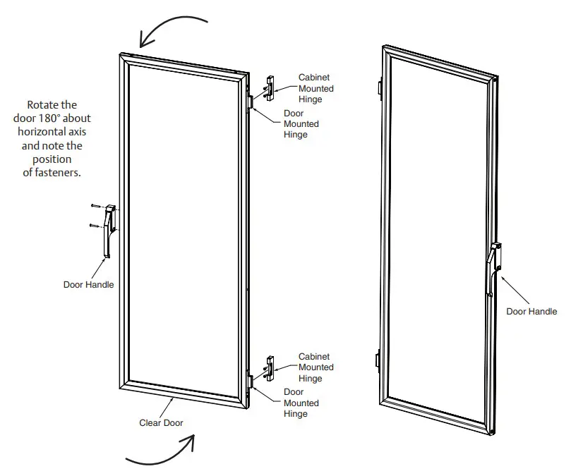
The door on your cabinet can be reversed to accommodate a right- or left-hand opening. The cabinet has been shipped with the hinges mounted on the right-hand side. To reverse, follow the instructions listed below:
- With the door in the closed position, remove the hinge pin by driving it out using a hammer and a drive pin or small-diameter screwdriver.
- Once the pins are removed grasp the door firmly and pull the latch lever, this will release the door. Set the door aside being careful not to damage the gasket.
- Remove the screws from the left side of the cabinet and set them aside. Then remove the cabinet-mounted part of the hinge and remount to the left side of the cabinet. Put the screws removed from the left side of the cabinet into the remaining holes on the right side of the cabinet. Tighten all screws before proceeding.
- Relocate the latch plate(s) from the left side to the right by removing the two mounting screws. Tighten all screws before proceeding.
- Rotate the door 180 degrees and align the door-mounted hinge part with the cabinet-mounted hinge part and tap the hinge pin into place so the top of the pin is flush with the top of the cabinet-mounted hinge part. Invert the door latch by removing the black plastic screw covers and remove the screws holding the latch in place.
C5 E-SERIES CABINET REPLACEMENT PARTS DIAGRAM
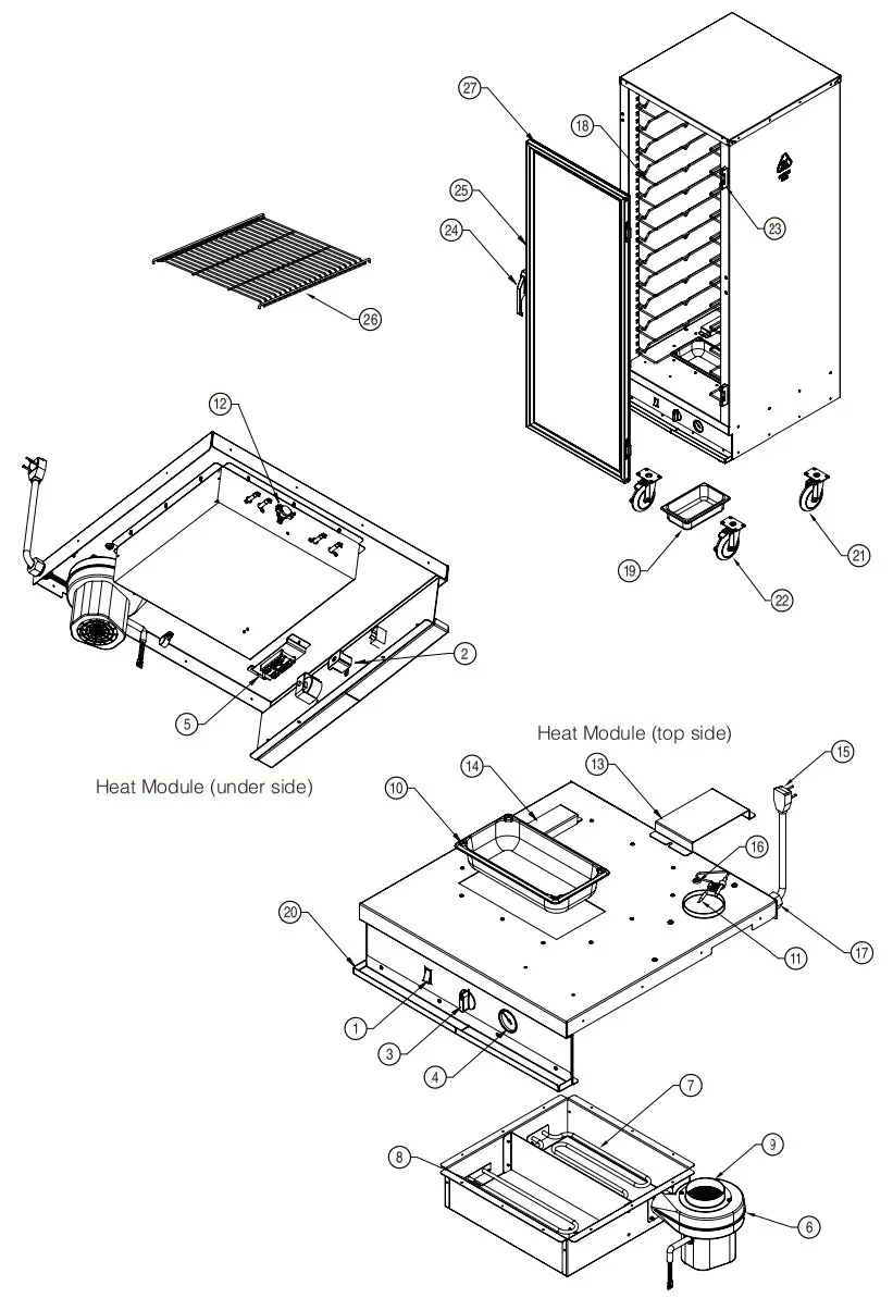
C5 E-SERIES SERVICE AND REPLACEMENT PARTS*
WARNING: Only factory-approved service agents must attempt to service, repair, or replace electrical components, wiring, or power cord.
Module
| Item# | Replacement Part No. | Description |
| RPC 13-1338 | Power-selector switch | |
| 2 | RPC13-721 | Thermostat |
| 3 | RPC06-914 | Thermostat Knob |
| 4 | RPC13-218 | Thermometer |
| RPC13-096 | Terminal Block | |
| 6 | RPHM20-2103 | Fan 120V |
| RPHX20-2103 | Fan 220-240V | |
| RPC 13-365 | 1950Watt Heating Element 120V | |
| RPC 13-370 | 1950Watt Heating Element 220-240V | |
| 8 | RPC13-367 | 675 Watt Heating Element 120V |
| RPC13-369 | 675 Watt Heating Element 220-240V | |
| 9 | RPC11-191 | Fan intake Collar |
| 10 | RPC11-185 | Stainless Steel Water Pan |
| 11 | RPC5-SCLP | Sensor and bulb Clamp Kit |
| 12 | RPC13-198 | Thermal Cut-out |
| 13 | RPC5E-INTCVR | Air Intake Cover |
| 14 | RPC5E-EXHCVR | Air Exhaust cover |
| 15 | RPC13-359 | Power cord (120V) |
| RPC13-247 | Power cord (220-240V) | |
| 16 | RPC07-055 | Rubber grommet |
| 17 | RP-STRNRLF | Strain Relief |
CABINET BODY
| Item# | Replacement Part No. | Description |
| 18 | C5-USLIDEPR-C | Universal wire slides (1 pair) |
| 19 | RPC06-179 | Plastic Drip Pan |
| 20 | RPC5E-DRIPTROUGH | Drip Trough (includes screws) |
| 21 | B5DN | 5″ swivel Caster |
| 22 | B5DNB | 5″ Brake Caster |
| 23 | RPC14-119 | Door Hinge (qty 1) |
| 24 | RPC14-118 | Door Handle |
| 25 | RPC5E-DOOR | Door (does not include hardware or gasket) |
| 26 | RPC5-SHELF-S | Accessory shelf |
| 27 | RPC07-104 | Door Gasket |
*CHECK THE DATA PLATE ON THE REAR OF THE CABINET TO CONFIRM CABINET VOLTAGE BEFORE SELECTING PARTS
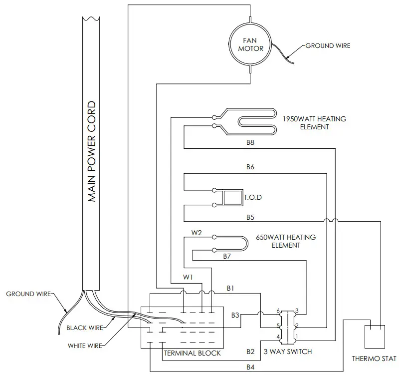
WIRING DIAGRAM 120V AND 220 / 240V
Warranty
WARRANTY, EXCLUSION OF WARRANTIES, AND LIMITATION OF LIABILITY.
lnterMetro Industries Corporation (hereinafter referred to as “Seller”) warrants to the original purchaser that all products in its catalog, or custom products, delivered hereunder will be free from defects in workmanship and material. THE FOREGOING WARRANTY IS EXCLUSIVE AND IN LIEU OF ALL OTHER WARRANTIES, EXPRESS, IMPLIED, OR STATUTORY, INCLUDING ANY WARRANTY OF MERCHANTABILITY OR FITNESS FOR A PARTICULAR PURPOSE. This Warranty shall be for a period of one (1) year from the date of shipment from Seller’s warehouse or factory.
If any product delivered hereunder does not meet the Warranty specified above, providing the product has not been altered in any way by anyone other than Seller’s factory-authorized representative, and assuming normal and proper use and maintenance, Seller will, at its option, repair or replace any part or material it determines, upon inspection, to be defective; provided, however, that a charge for labor will be made except during a period of one (1) year from the date of original shipment from Seller’s warehouse or factory. No product, or part thereof, is to be returned to Seller without prior written approval from Seller’s factory. All exchanges and replacement shipments will be at F.O.B. Seller’s factory. Warranties for equipment or articles not manufactured by the Seller are solely the warranties of the manufacturers thereof and they are hereby assigned to the purchaser without recourse to the Seller.
SELLER’S LIABILITY FOR ANY CLAIM OF ANY KIND, WHETHER BASED ON CONTRACT, NEGLIGENCE, OR STRICT LIABILITY IN TORT, AND BY WHOMEVER MADE, FOR ANY DIRECT, INDIRECT, INCIDENTAL OR CONSEQUENTIAL LOSS, DAMAGE OR INJURY, RESULTING TO THE PURCHASER OR ANY THIRD PARTIES, arising out of, connected with or resulting from this Agreement, or from the performance or breach thereof, or from the manufacture, sale, delivery, resale, installation, inspection, repair or use of any product covered by or furnished under this Agreement, WHETHER OR NOT CAUSED BY SELLER’S NEGLIGENCE, SHALL IN ALL EVENTS BE EXCLUSIVELY LIMITED TO THE COST OF CORRECTING DEFECTIVE, DAMAGED OR NON- CONFORMING PARTS OR MATERIAL AS HEREIN PROVIDED, and upon the expiration of one (1) year, all such liability shall terminate.
SELLER DOES NOT AUTHORIZE any person to assume for it any obligations or liabilities greater than or different than those set forth in this Warranty. The terms under which any of Seller’s products may be resold must be limited in accordance with this Warranty.
THIS AGREEMENT, and all the rights and obligations arising hereunder, shall be construed in accordance with, and be governed by, the law of the Commonwealth of Pennsylvania, U.S.A.
TO INSURE WARRANTY implementation, return the completed registration card within 15 days of cabinets’ receipt to: lnterMetro Industries Corp., Wilkes-Barre, PA 18705
![]() lnterMetro Industries Corporation
lnterMetro Industries Corporation
Wilkes-Barre, PA 18705
For online warranty registration, please go to www.metro.com/service-support/thermal-cabinets to register electronically
US/Can: 1.800.992.1776
Corporate Headquarters (US): 1.570.825.2741
For Inquiries Outside of the U.S. and Canada, Visit www.metro.com/contactus


