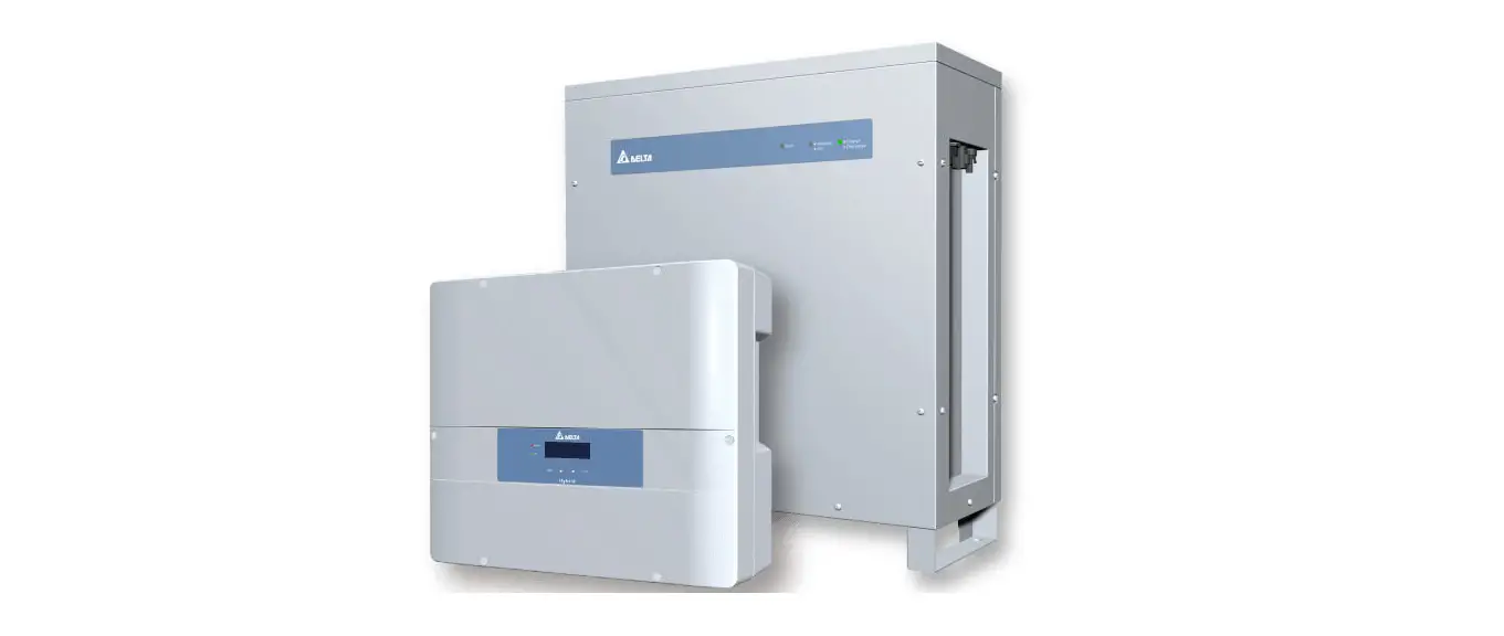
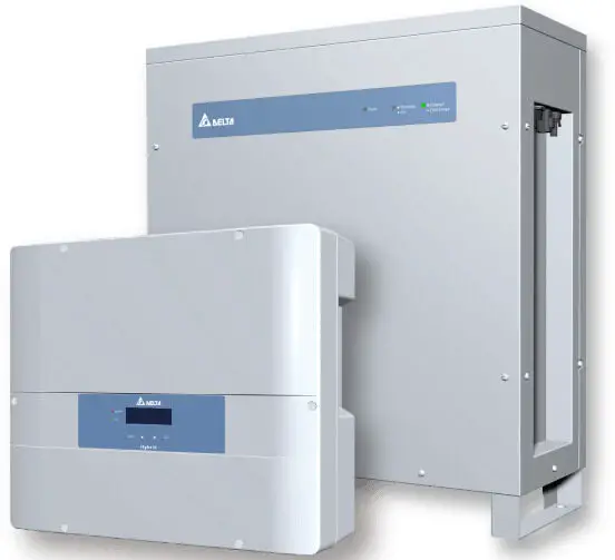
DELTA BX6.3_DD Battery Storage System
BX6.3_DD user manual
For more instruction and specification, please scan QR-code to see user manual.
Battery > BX6.3_DD Operation and Installation Manual
– https://mydeltasolar.deltaww.com/?p=product_manual

Descriptions of Components
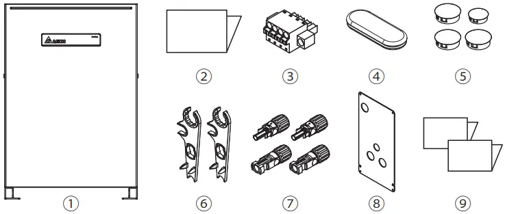
| Object | Qty | Description | |
| ① | Delta BX6.3_DD | 1 | Residential DC ESS |
| ② | Quick Installation Guide (English) | 1 | The Instruction to provide the information of safety, installation and specification. |
| ③ | Communication connector | 1 | Connector for inverter communication board |
| ④ | Rubber cover | 1 | Protective cover for non-critical waterproof and dust prevent |
| ⑤ | Plastic cover | 4 | |
| ⑥ | H4 Wrench | 2 | To disconnect H4 connector |
| ⑦ | H4 Connector | 2 pair | Connector for inverter |
| ⑧ | Wiring Cover | 1 | Protective cover to prevent users from touching the power cable |
| ⑨ | Japanese Manual * | 2 | User manual and Quick install guide in Japanese |
* Japanese manual is only intended for Japanese market.
LED Indicators
| LED Status | Definition |
| GREEN FLASH | Standby mode |
| ORANGE ON | Charge |
| GREEN ON | Discharge |
| RED FLASH | Boot up / Shut down |
| RED ON | BMS error |
| RED & GREEN FLASH ALTERNATELY | Programming |
| Status | Operation | Action |
| BX6.3_DD power OFF | Power button push > 20 sec (until grid green LED flash) | Power ON the unit (Cold start-up) |
| BX6.3_DD power ON already | Power button push >1 sec | Power OFF the unit |
| Warning | |
| Do not open this product or insert tools due to shock and fire hazard which may cause injury. | |
| The following instructions must be adhere when installing: ● The product is intended to be installed and operated by qualified personnel or service personnel only. ● Do not power up the device before installation is complete. ● All circuit breakers must be in the OFF position before commencing installation. | |
| ● Do not install BX6.3_DD near or on flammable surfaces. ● Please mount BX6.3_DD tightly on a solid / smooth surface. ● Install BX6.3_DD in a location that prevents damage from flooding. ● Do not expose BX6.3_DD to ambient temperatures above 60°C or below -20°C. ● Operating or storing BX6.3_DD in temperatures outside its specified range might cause damage to BX6.3_DD. | |
|
60 seconds | Danger to life through electric shock Potentially fatal voltage is applied to the unit during operation. Voltage persists 60 seconds after disconnection of power supply. Never open the unit. The unit contains no components that must be maintained or repaired by the operatoror installer. Opening the housing will void the warranty. |
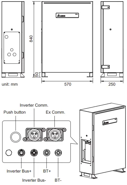
Dimensions and Interface Overview
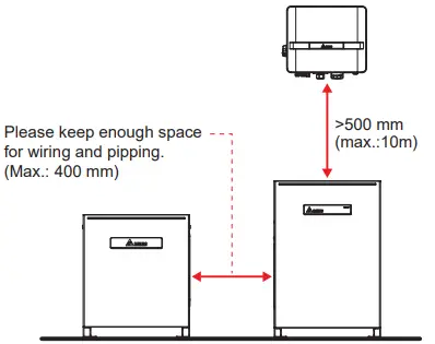
Installation
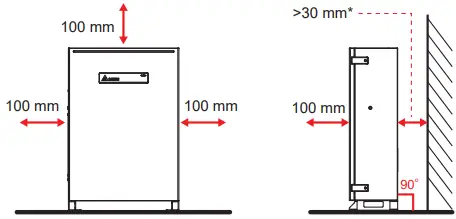
* Please refer to regulation AS/NZS 5139:2019 for detail installation space requirement. To avoid extra fireproof cement sheeting installation requirement, it is recommended to keep at least 300mm between the wall and BX.
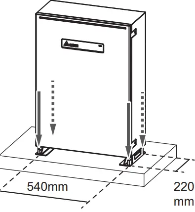
Insert Rawlplug

- Drill 4 holes with Φ16 mm diameter in dimension 540mm x 220mm.
- Insert Rawlplugs into the holes.
- Fix the foot of BX6.3_DD firmly.
- Tighten the nut to stretch the rawlplug.

Wiring
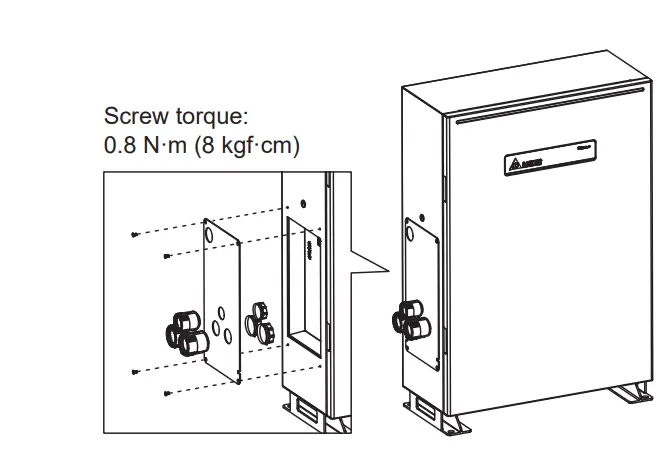
| Conduit hole(mm) | PF pipe(mm) |
| Φ34 | Φ28 |
| Φ27 | Φ22 |
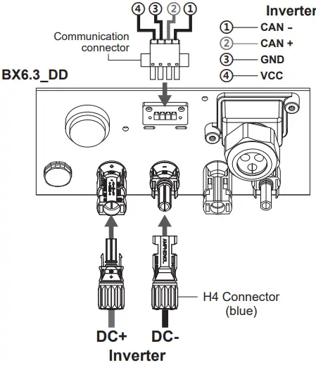
Inverter connection
Specification
| Model | BX6.3_DD | BX6.3_DD+BX6.3_EX100 |
| GENERAL | ||
| Enclosure | Aluminum with powder coating | |
| Operating temperature | -10℃ * ~ 45℃ | |
| Operating Altitude | 0 to 2000m (0 to 6666 ft.) | |
| Relative humidity | 0% – 95% non-condensing. | |
| Environmental category | Indoor / Outdoor | |
| Protection degree | IP65 (Electronics) | |
| Pollution degree | PD 2 | |
| Overvoltage category | Other: not connected to mains directly | |
| Galvanic isolation | NO | |
| Safety class | Class I metal enclosure with protective earth | |
| Weight | 75kg | 75 kg (BX6.3_DD) + 60 kg (BX6.3_EX) |
| Dimensions(W*H*D) | 570 × 840 × 250 mm | 570 × 840 × 250 mm + 520 × 600 × 230 mm |
| Connectors | Weather resistant connectors | |
| Audible noise | < 40dB | |
| BT INPUT | ||
| Type | Li-ion | |
| Battery Module | Samsung SDI 41J (21700) | |
| Typical Energy | 6.3 kWh | 12.6 kWh |
| Typical Voltage | DC 202.7 V | DC 405.4 V |
| Voltage Range | DC 175 – 228 V | DC 350 – 456 V |
| Depth of Discharge (DoD) | 98% | |
| DC BUS INPUT / OUTPUT | ||
| Nominal power | 3000 W | 6000 W |
| Maximum power | 3000 W | 6000 W |
| Voltage | 250V – 1000V | |
| Maximum input/ output current | 15.6 A | 15.6 A |
| Maximum fault current | 25A | |
| Tare loss | < 10 W | |
| Maximum efficiency | 99% | |
| REGULATIONS & DIRECTIVES | ||
| Electrical safety | IEC 62619:2017, IEC 60730-1:2013 | |


