DMEGC H01 Lithium-ion Battery

Packing List
Note: The quick installation guide briefly describes required installation steps. If you have any questions during the installation, please refer to the User Manual for more detailed information.
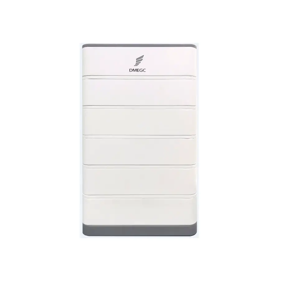
H01 battery master/bottom case and accessories.
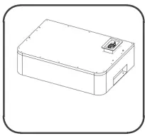
- H01 Battery Master x1

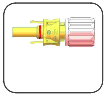
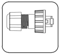
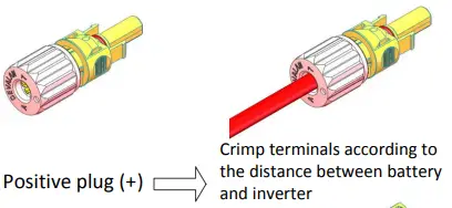
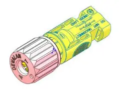
- Positive plug x1
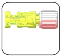
- Negative plug x1
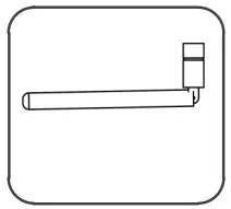
- RJ45 Plug x2
- User manual x1
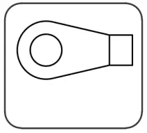
- Ground terminal x1
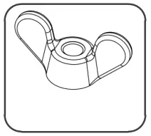
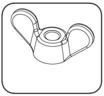
- Butterfly nut x4
- Wi-fi Monitor x1
- Quick Installation Guide x1
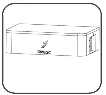
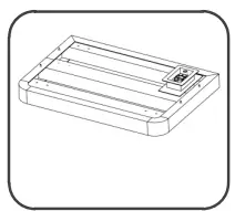
- H01 bottom case x1
H01 battery slave and accessories - H01 Battery Slave x1

- Butterfly nut x4

Installation Prerequisites
Make sure that the installation location meets the following conditions:
- The building is designed to withstand earthquakes
- The location is far away from the sea, to avoid sea water and humid air
- The floor is flat and level
- There are no flammable or explosive materials nearby
- The ambience is shady and cool, keep away from heat as well as direct sunlight
- The temperature and humidity stay at a constant level
- There is minimal dust and dirt in the area
- There is no corrosive gases present, including ammonia and acid vapor
- The ambient temperature is with the range from 0℃ to 55℃ and the optimal ambient temperature is between 15℃ and 35℃.
Notice
The H01 battery is rated at IP65 and thus can be installed outdoors as well as indoors. However, if installed outdoors, do not expose the battery to directly sunlight and moisture.
Notice
If the ambient temperature is beyond the operating range, the battery pack will stop operating to protect itself. The optimal temperature range for the battery pack to operate is from 15℃ to 35℃. Frequent exposure to harsh temperatures may deteriorate the performance and lifetime of the battery module.
Battery Installation
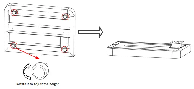
Bottom Case Installation
- Adjust the feet manually so that the bottom case can be on the ground steadily.

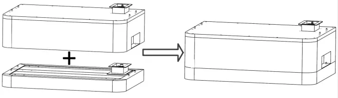
Battery Slave Installation
- Place the battery slave onto the bottom case (2≤ Qty of battery slave ≤8)

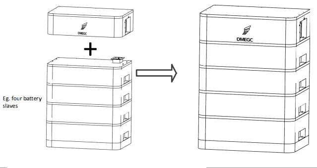
Battery Master Installation
- Place the battery master onto the battery slave.

Notice No more than eight batteries are allowed to be stacked
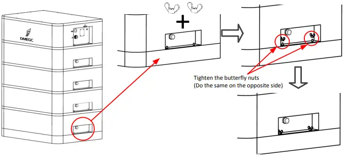
Fix the battery master, slave and bottom case
- Fix battery slave and bottom, battery master and battery slave with butterfly nuts.

Notice Butterfly nuts are required on both sides of battery master and battery slave.
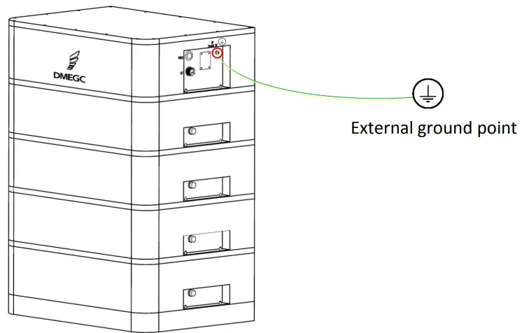
Ground cable connection
- Crimping Ground terminal

Ground terminal
Crimp terminals according to the distance between battery and external ground point.

Communication cable connection
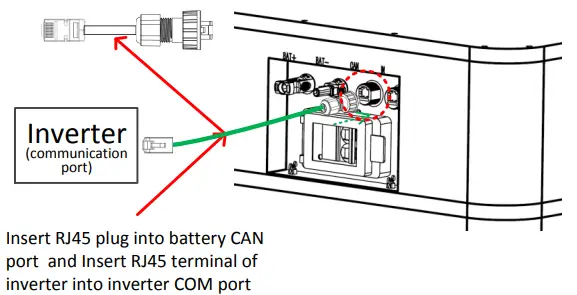
Battery to inverter communication cable connection
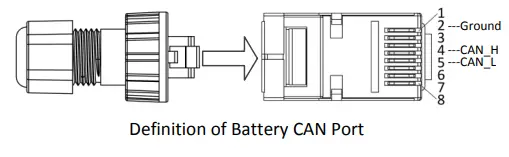
Caution:
When Crimping RJ45 plug terminal, only 2,4 and 5 PIN are needed. 4PIN is CAN_H and 5PIN is CAN_L.2PIN is ground. Note that the RJ45 definition of inverter refer to the inverter definition.
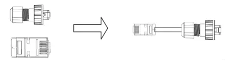
- Crimping RJ45 plug terminal.

Take out RJ45 plug of battery master and RJ45 terminal of inverter
Crimp terminals according to the distance between battery and inverter

Battery to battery communication cable connection
(Only used when battery cluster in parallel)
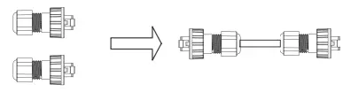
- Crimping RJ45 plug terminal.

Take out RJ45 plug from two battery master accessories
Crimp terminals according to the distance between battery and battery
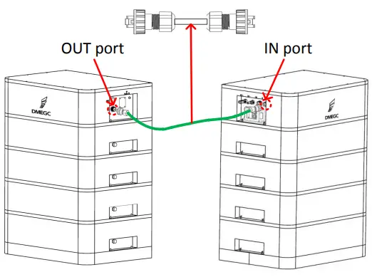
Insert one end of communication parallel cable into last battery OUT port and another into next battery IN port
Power cable connection
Single Battery cluster
Negative plug (-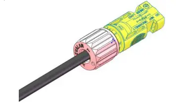
Crimp terminals according to the distance between battery and inverter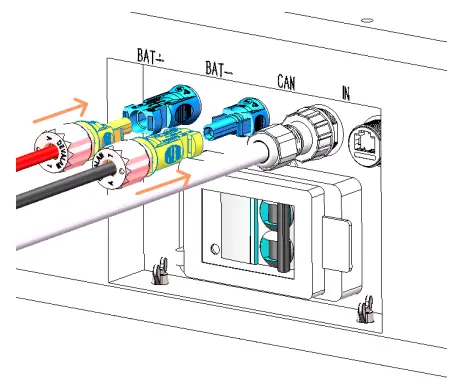
Insert positive plug and negative plug into battery port
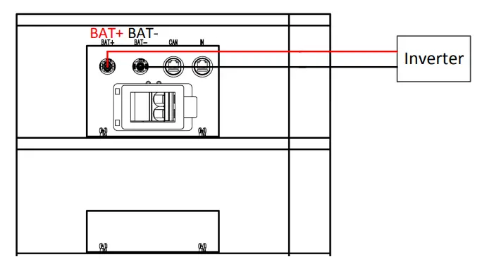
Single Battery cluster
- Power Wiring Diagram

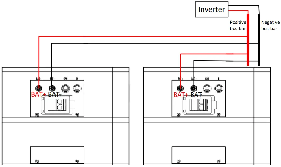
Battery cluster in Parallel
- Power Wiring Diagram

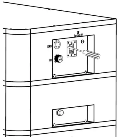
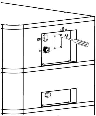
Set DIP switch
- Remove the cover plate screws

- Rotate the DIP switch to corresponding number with small tool. For inverter brands corresponding to different numbers, please refer to inverters brand table provided by DMEGC.

- -Reinstall the cover plate


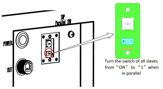
Set parallel switch
-Single battery cluster
- Keep factory settings, remaining it at “ON”
-Battery cluster in parallel
- Turn the switch of all slave H01 system from “ON” to “1”
- The master keep factory settings

Wi-fi monitor installation
Take out Wi-fi monitor and plug into the battery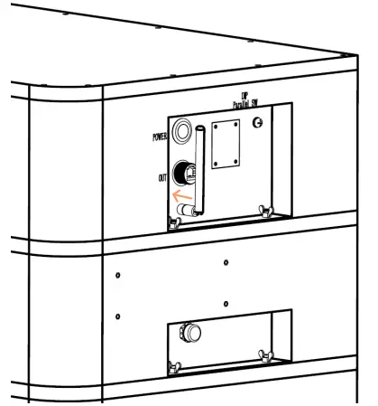
Commissioning
If all the preparatory work is ok, follow these steps to put it in operation.
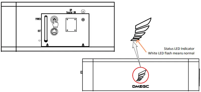
- Press the POWER button to “on” to start the H01 battery system.
- Check whether the status LED indicator is normal.
- Power on the inverter.

![]()


