
DELTA BX6.3_AC100 Battery Storage System
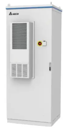
BX6.3_AC100 user manual
For more instruction and specification, please scan QR-code to see user manual.
- Battery > BX6.3_AC100 Operation and Installation Manual https://mydeltasolar.deltaww.com/?p=product_manual
Descriptions of Components
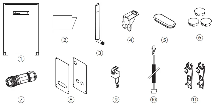
| Object | Qty | Description | |
| 1 | Delta BX6.3_AC100 | 1 | Residential AC ESS |
| 2 | Quick Installation Guide | 1 | The Instruction to provide the information of safety, Installation and specification. |
| 3 | WiFi antenna | 1 | 2.4 Ghz Wi-Fi Antenna (IPX7) |
| 4 | Antenna Bracket | 1 | To support Wi-Fi antenna on BX6.3_AC100 |
| 5 | Rubber cover | 1 | Protective cover for non-critical waterproof and dust prevent |
| 6 | Plastic cover | 3 | Protective cover for non-critical waterproof and dust prevent |
| 7 | AC Plug | 1 | Connector for AC connection |
| 8 | Wiring Cover | 2 | Protective cover to prevent users from touching the power cable |
| 9 | Current sensor | 1 | 120A current transformer |
| 10 | CT cable | 1 | Cable for CT connection |
| 11 | H4 Wrench | 2 | To disconnect H4 connector |
Dimensions and Interface Overview
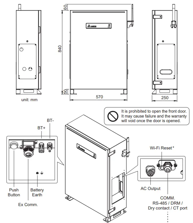
Wi-Fi reset button function
| Operation | Wi-Fi LED Status | Explanation |
| Push 3s~10s | Wi-Fi LED flashing once every half a second | Reset Wi-Fi module |
| Push 10s~20s | No flash | No function |
| Push 20s~ | Wi-Fi LED flashing once every one seconds | Reset Wi-Fi module, and Wi-Fi password returns to the default: DELTASOL |
Warning
- Do not open this product or insert tools due to shock and fire hazard which may cause injury.
When installing this product you must adhere to the following instructions:
- The product is intended to be installed and operated by qualified personnel or service personnel only.
- Do not power up the device before installation is complete.
- All circuit breakers must be in the OFF position before commencing installation.
- Do not install BX6.3_AC100 near or on flammable surfaces.
- Please mount BX6.3_AC100 tightly on a solid / smooth surface.
- Install BX6.3_AC100 in a location that prevents damage from flooding.
- Do not expose BX6.3_AC100 to ambient temperatures above 60°C or below -20°C.
- Operating or storing BX6.3_AC100 in temperatures outside its specified range might cause damage to BX6.3_AC100.
Danger to life through electric shock
Potentially fatal voltage is applied to the unit during operation. This voltage persists even 60 seconds after the disconnection of the power supply. Never open the unit. The unit contains no components that must be maintained or repaired by the operator or installer. Opening the housing will void the warranty.
LED Indicators
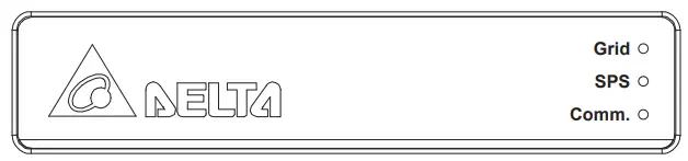
| LED | LED Status | Definition |
| Grid | GREEN ON | On Grid mode |
| GREEN FLASH 1s ON/OFF | On Grid count down | |
| GREEN FLASH 0.1s ON/OFF | Grid setting “default” | |
| RED ON | PCS Error | |
| SPS (Stand-alone Power System) | GREEN ON | Standalone mode |
| GREEN FLASH | Standalone count down | |
| RED ON | Battery Error | |
| RED FLASH | Battery Power OFF | |
| Comm. | GREEN ON | Communicating |
| OFF | No communication | |
| Grid / SPS | GREEN FLASH Grid ON 1s SPS ON 1s | SBMS Balance mode SBMS Force_CHG Maintenance Mode |
| Status | Operation | Action |
| BX6.3_AC100 power OFF | Grid supplied | Power ON the unit (AC start-up) |
| BX6.3_AC100 power OFF | Power button push > 20 sec (until grid green LED flash) | Power ON the unit (Cold start-up) |
| BX6.3_AC100 power ON already | Power button push >1 sec | Power OFF the unit |
Installation
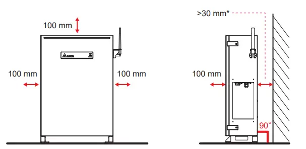
- Please refer to regulation AS/NZS 5139:2019 for detail installation space requirement. To avoid extra fireproof cement sheeting installation requirement, it is recommended to keep at least 300mm between the wall and BX.

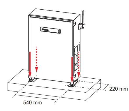
Insert Rawlplug
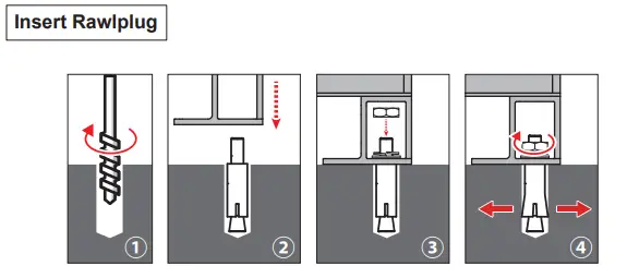
- Drill 4 holes with Φ16 mm diameter in dimension 540 mm x 220 mm
- Insert Rawlplug into these hole
- Put on and fix BX6.3_AC100 firmly
CAUTION!
- Please do not install the battery pack on uneven floor surfaces.
- Holes size is 16 mm diameter for attaching the battery pack.

Wiring
- Conduit hole(mm)
- Φ34
- PF pipe(mm)
- Φ28
Screw torque:0.8 N·m (8 kgf·cm)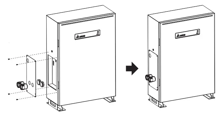
- Please do not remove all the rubber covers on BX6.3_AC100 if BX6.3_EX100 is not installed.
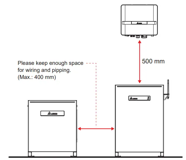
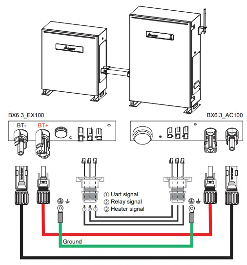
Installation of BX12.6_AC100
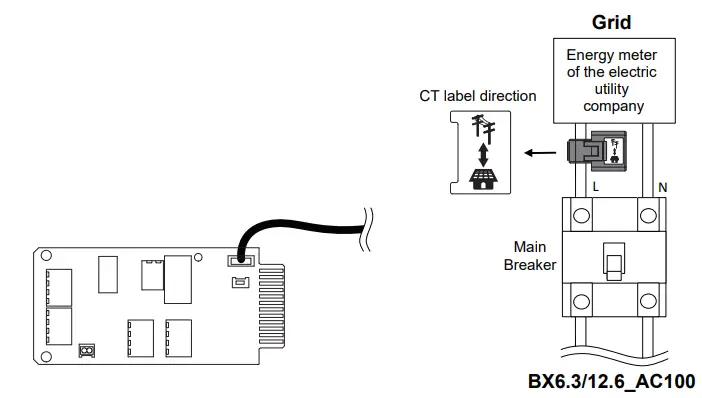
Current Transformer installation
- The CT can be opened.
- Take the CT clip on the Line conductor wire.
- please be aware of the CT direction. Arrow symbol means utility grid.
- Connect the CT wires to the device.
- Connect CT wire to the CT port of communication card.

| Model | BX6.3_AC100 | BX12.6_AC100 | |
| GENERAL | |||
| Enclosure | Aluminum with powder coating | ||
| Operating temperature | -10℃ * ~ 45℃ | ||
| Operating Altitude | 0 to 2000m (0 to 6666 ft.) | ||
| Relative humidity | 0% – 95% non-condensing. | ||
| Environmental category | Indoor / Outdoor | ||
| Protection degree | IP65 (Electronics) | ||
| Pollution degree | PD 2 | ||
| Overvoltage category | AC output :III | ||
| Galvanic isolation | NO | ||
| Safety class | Class I metal enclosure with protective earth | ||
| Weight | 77kg | 77 kg (BX6.3_AC) + 60 kg (BX6.3_EX) | |
| Dimensions(W*H*D) | 570 × 840 × 250 mm | 570 × 840 × 250 mm + 520 × 600 × 230 mm | |
| Connectors | Weather resistant connectors | ||
| Audible noise | < 40dB | ||
| BT INPUT | |||
| Type | Li-ion | ||
| Battery Module | Samsung SDI 41J (21700) | ||
| Typical Energy | 6.3 kWh | 12.6 kWh | |
| Typical Voltage | DC 202.7 V | DC 405.4 V | |
| Voltage Range | DC 175 – 228 V | DC 350 – 456 V | |
| AC INPUT / OUTPUT | |||
| Nominal power | 3000 VA | 4500 VA | |
| Maximum power | 3000 VA | 4500 VA | |
| Voltage | According to country setting (Programmable 230Vac ± 20%) | ||
| On Grid Nominal current | 13 A | 19.6 A | |
| Stand-Alone Nominal current | 13 A | 19.6 A | |
| Inrush current | 16 A / 100 us | ||
| Maximum output fault current (rms) | 25 A | 25 A | |
| Maximum overcurrent protection | 25 A | 25 A | |
| Frequency | Rated 50/60 Hz (Programmable 45-65 Hz) | ||
| Active anti-islanding method | Reactive power injection | ||
| Total harmonic distortion | < 3 % | ||
| Power factor | > 0.99 @ full power | ||
| Output current DC component | < 0.5% rated current | ||
| Tare loss | < 10 W | ||
| Maximum efficiency | 96.5% | ||
| SYSTEM INFORMATION / COMMUNICATION | |||
| User interface | Wi-Fi connection | ||
| 365 days data logger and real time clock | |||
| 30 events record | |||
| External communication | 2 RS-485 connections | ||
| REGULATIONS & DIRECTIVES | |||
| CE conformity | Yes | ||
| Grid interface | AS/NZS 4777.2 :2015 | ||
| Emission | EN 61000-6-3 | ||
| Harmonics | EN 61000-3-2 | ||
| Variations and flicker | EN 61000-3-3 | ||
| Immunity | EN 61000-6-2 | ||
|
Immunity | ESD | IEC 61000-4-2 | |
| RS | IEC 61000-4-3 | ||
| EFT | IEC 61000-4-4 | ||
| Surge | IEC 61000-4-5 | ||
| CS | IEC 61000-4-6 | ||
| PFMF | IEC 61000-4-8 | ||
| Electrical safety | IEC 62619:2017, IEC 62040-1:2017 | ||
- degree for the first time installation.


