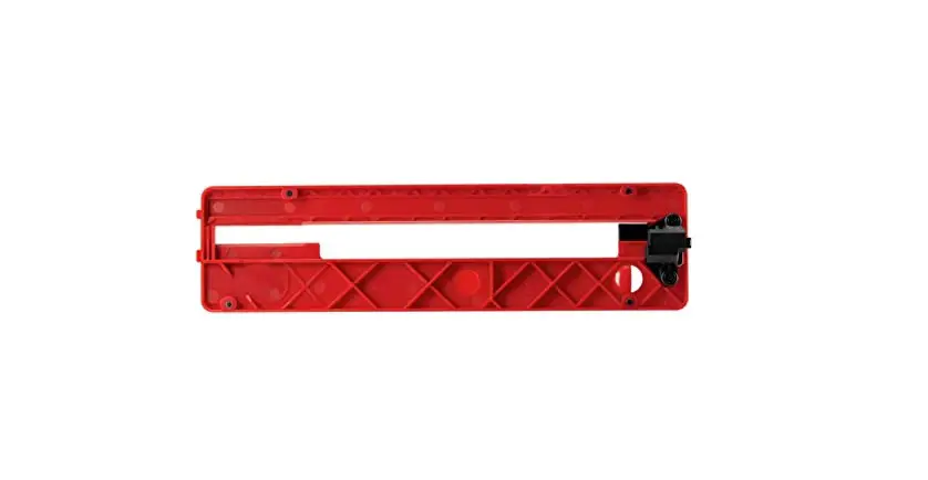
SKIL STZ6307 Zero Clearance Insert Owner’s Manual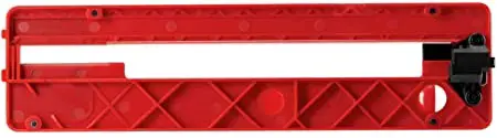
Inductions
![]() WARNING: This zero clearance insert is designed specifically for use only with SKIL TS6307-00 table saw.
WARNING: This zero clearance insert is designed specifically for use only with SKIL TS6307-00 table saw.
![]() WARNING: Read the table saw manual for use of this accessory with the saw.
WARNING: Read the table saw manual for use of this accessory with the saw.
NOTICE: This accessory is for 90° cuts only. Do not use it for bevel cuts.
- Disconnect the saw from power source.
- Remove the barrier guard assembly, the anti-kickback device, and the existing table insert from the saw as instructed in the saw manual.
- Place the riving knife to its lowest position and lock it in place.
 WARNING The riving knife should be adjusted to and locked in the lowest position when making the initial cut in the zero clearance insert.
 - Lower the blade completely below the table surface.
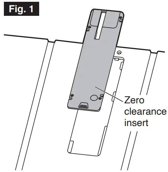
- Place the zero clearance insert in the table opening as shown in Fig. 1.

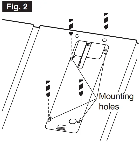
- Use the mounting holes of the zero clearance insert to drill four holes Ø1/8–9/64 inch (3.2–3.5 mm) in the supports for the insert plate as shown in Fig. 2.

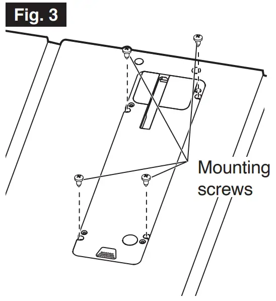
- Use a Philips head screwdriver to secure the zero clearance insert in place with the four (4) included #8×3/8” self-tapping mounting screws as shown in Fig. 3.

- Connect the saw to a power source.
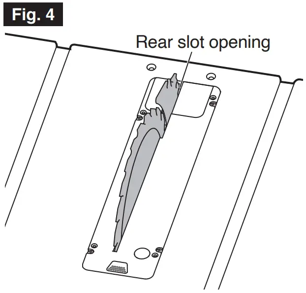
- Turn the saw on and slowly raise the blade as high as it will go until the blade cuts completely through the insert to reach the rear slot opening (Fig. 4).

- Disconnect the saw from power source.
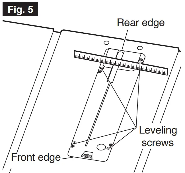
- Level the zero clearance insert:
- a. The zero clearance insert should be flush* with the saw table surface.
- b. Place a straight edge (such as the metal ruler from a combination square) across the saw table and the insert – the surfaces should be at the same level (Fig. 5).
* The front edge of the insert may be below the saw table by the thickness of a piece of paper folded twice. Place the folded paper between the insert and straight edge to check. The rear edge may be above the saw table by the same amount. - c. If adjustment is necessary, use a 2.5mm hex wrench (not included) to adjust four (4) leveling screws (Fig. 5).

- Remove the zero clearance insert. Raise the riving knife and reattach the barrier guard assembly and the anti-kickback device as instructed in the saw manual.
- Reinstall the zero clearance insert.
![]() WARNING: An improperly leveled insert can result in binding which could result in personal injury. Verify adjustments by making a dry cut before using the saw.
WARNING: An improperly leveled insert can result in binding which could result in personal injury. Verify adjustments by making a dry cut before using the saw.![]() WARNING: Never operate the saw without the proper insert in place. Use the saw insert when sawing and the dado insert when using a dado set.
WARNING: Never operate the saw without the proper insert in place. Use the saw insert when sawing and the dado insert when using a dado set.
Support
![]() For Customer Service
For Customer Service
Pour le service à la clientèle
Servicio al cliente
1-877-SKIL-999 OR
www.skil.com