
- Never put your fingers, hands or any other parts of the body into the spray jet!
Never point the spray gun at yourself, other persons or animals.
Never use the spray gun without a safety guard. - Do not treat a spraying injury as a harmless cut. In case of injury to the skin through coating materials or solvents, consult a doctor immediately for quick and expert treatment. Inform the doctor about the coating material or solvent used.
The operating instructions state that the following points must always be observed before starting up:
- Faulty units must not be used.
- Secure the spray gun using the safety catch on the trigger.
- Ensure that the unit is properly earthed. The connection must take place through a correctly earthed two-pole and earth socket outlet.
- Check the allowable operating pressure of the high-pressure hose and spray gun.
- Check all connections for leaks.
- Release the pressure from spray gun and hose
- Secure the spray gun using the safety catch on the trigger.
- Switch off unit
You have purchased a proprietary device that requires careful cleaning and care to ensure trouble-free functioning. Read the operating instructions carefully before using the tool and observe the safety instructions. Keep the operating instructions in a safe place.
Explanation of symbols used
Danger | Indicates an immediate danger. Unless avoided, death or serious injuries will result. |
 | Indicates tips for use and other particularly useful information. |
| Wear suitable ear protection when working. | |
| Wear suitable respiratory equipment when working. | |
 | Wear suitable safety gloves when working. |
General Safety Instructions
- Safety at the workplacea) Keep your workplace clean and well-lit. Disorder or unlit workplaces may result in accidents.b) Never use the tool in hazardous areas that contain flammable liquids, gases or dust. Power tools generate sparks that can ignite the dust or vapors.c) Keep children and other persons away when using the power tool. You can lose control of the tool if you are distracted.
- Electrical Safetya) The tool plug must fit into the socket. The plug may not be modified in any form. Do not use adaptor plugs together with protective-earthed tools. Unmodified plugs and suitable sockets reduce the risk of an electric shock.b) Avoid physical contact with earthed surfaces such as pipes, heating elements, stoves and refrigerators. The risk of electric shock increases if your body is earthed.c) Keep the equipment away from rain and moisture. The risk of an electric shock increases if water penetrates electrical equipment.d) Do not misuse the mains lead by carrying the tool by the lead, hanging it from the lead or by pulling on the lead to remove the plug. Keep the lead away from heat, oil, sharp edges or moving tool parts. Damaged or twisted leads increase the risk of an electric shock.e) If you work outdoors with a power tool, only use extension cables suitable for outdoor use. The use of an extension lead that is suitable for outdoors reduces the risk of an electric shock.f) If you cannot avoid using the tool in a damp environment, use a residual current-operated circuit breaker. Using a residual current operated circuit-breaker avoids the risk of electric shock.
Safety of Persons
c) Avoid accidental starting-up. Ensure that the switch is in the “OFF” position before inserting the plug into the socket. Accidents can occur if you carry the power tool while your finger is on the switch or if you connect the power tool to the power supply which it is on.
Flammable maeteriales
Always secure the spray gun when mounting or dismounting the nozzle and in case of interruption to work.
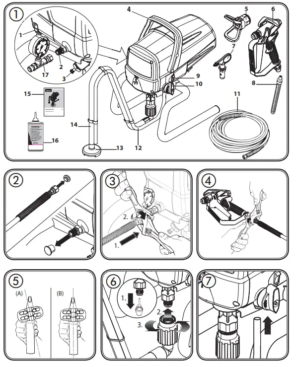
DescriniOn Fie . 1 | |
| 1 Pressure regulator | 2 Hose connection |
| 3 Inlet valve pusher | 4 Carry handle |
| 5 NO771P holder | 6 Spray Gun |
| 7 Nozzle 517 | 8 Filter (white)’ |
| 9 ON i OFF Switch (0 = OFF. I = ON) | 10 Selector switch |
| 11 High-pressure hose | 12 Return line |
| 13 Inlet filter | 14 Suction hose |
| 15 Operating instructions | 16 Oil |
| 17 Pressure gauge | |
- Adjustable wrench (2 pcs.)
- Empty container
- A large piece of cardboard
- Covering material
No liability is assumed for damage due to overspray.
Preparation of the Coating Material
- Stir the material thoroughly and dilute it in the container as per the recommended dilution (an agitator is recommended for stirring).
| Thinning recommendation | |
| Sprayed material | |
| Glazes | undiluted |
| Wood preservatives containing solvents or based on water, mordants, oils, disinfection agents, plant protective agents | undiluted |
| Paints containing solvents and water-soluble paints, primers. vehicle coating paints. thick-film glazes | dilute by 5 – 10 % |
| Interior wall paint (dispersions and latex paint) | dilute by 0-10 % |
Assembly
- Remove the protective covers on the hose and hose connection. (Fig. 2)
- Screw the pressure gauge to the hose connection.
- Screw the high-pressure hose onto the pressure gauge.Keep hold of the connection using an adjustable spanner and tighten the hose connection with another spanner. (Fig. 3)
- Screw the thread at the other end of the hose to the spray gun connection. Keep hold of the spray gun by applying an adjustable spanner to the handle and tighten the hose nut using another spanner. (Fig. 4)
- Place the nozzle holder on the spray gun (Fig. 5A ) and rotate it into the final position (Fig. 5B), in order to fix it.
- Pull the red shutter out of the paint entry point. (Fig. 6, 1)
- Connect the suction hose to the paint entry point and secure into position. (Fig. 6, 2 and 3)
- Push the return line on to the return flow connector. (Fig. 7)
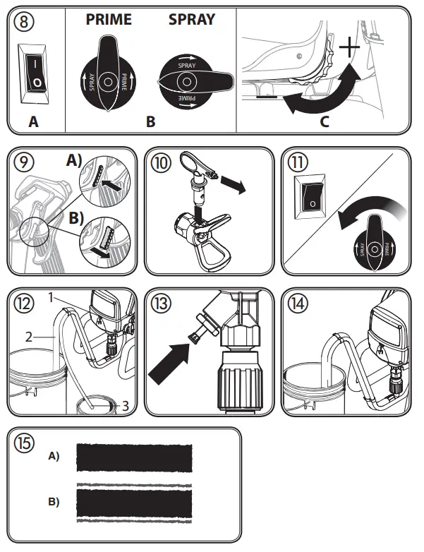
Control elements on the device (Fig. 8)
A The ON/OFF switch turns the power to the sprayer on and off (O=OFF, I=ON).
The following settings can be made with the selector switch:
PRIME (Switch set vertically)
→ • For prefilling the system with paint
→ • For pressure relief SPRAY (Switch set horizontally)
→ • For using the spray gun
C The pressure of the spray is set by the pressure regulator. The correct spray pressure depends on the paint being used.
Spray Gun
- To lock the trigger, push in the trigger lock from left to right, when looking at the rear of the gun. (Fig. 9, A)
- To unlock the trigger, push the trigger lock from right to left, when looking at the rear of the gun. (Fig. 9, B)
- Insert the nozzle with the tip pointing forwards. (Fig. 10)
- Secure the spray gun. (Fig. 9, A)
- Switch the device off. Turn the switch into the PRIME position (vertical). (Fig. 11)
- Release the spray gun. Hold the spray gun over an empty container and press the trigger to relieve the pressure.
- Secure the spray gun.
- Spray a little oil out of the provided flask into the marked opening (fig. 12, 1). Tip: tilt the device back. Light household oil can be substituted if necessary.
- Disconnect the return flow pipe from the suction hose.
- Place the suction hose (Fig. 12, 2) in the material container and the return line (Fig. 12, 3) in an empty container.
- Press the red inlet valve pusher to ensure that the inlet valve is free. (Fig. 13)
- Plug in the power cable.
- Turn the switch into the PRIME position (vertical).
- Hold the return line over the empty container and switch the device on. This will flush out any preservatives remaining in the system.
- Switch the device off again as soon as the material emerges from the return line
- Fix the return line using the suction hose clips. (Fig. 14)
- Turn the switch to the SPRAY position (horizontal).
- Aim the spray gun at a piece of cardboard and switch the device on.
- Release the spray gun and hold the trigger until the material emerges evenly.
- Let go of the trigger and secure the spray gun
Spray Technique
- It is best to practice on cardboard or a similar surface first of all, in order to check the spray pattern and become accustomed to using the spray gun. If the paint sprays evenly, as shown in fig. 15 A, all the settings must be correct. If the paint looks stripy after spraying, as shown in fig. 15 B, gradually increase the pressure or dilute more in 5% steps (please note the maximum amount of thinner stipulated by the manufacturer.)
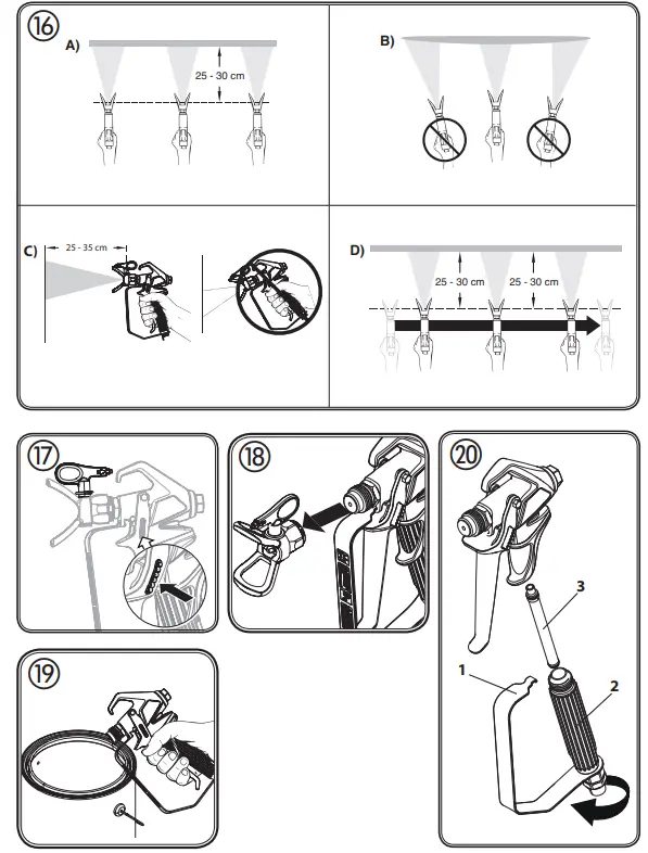
- The key to obtaining a high-quality result is even coating of the entire surface. Keep your arm moving at a constant speed and keep the spray gun at a constant distance from the surface. The best spraying distance is approx. 25 to 30 cm between the spray nozzle and the surface. (Fig. 16, A)
- Keep the spray gun at right angles to the surface. This means moving your entire arm back and forth rather than just flexing your wrist. (Fig. 16, B)
- Keep the spray gun perpendicular to the surface, otherwise, one end of the pattern will be thicker than the other. (Fig. 16, C)
- Trigger gun after starting the stroke. Release the trigger before ending the stroke. (Fig. 16, D) The spray gun should be moving when the trigger is pulled and released. Overlap each stroke by about 30%. This will ensure an even coating. During operation, the pump switches on and off continuously, in order to regulate the pressure. This is normal and is not a malfunction.
- Release the trigger and secure the gun. Rotate the reversible nozzle arrow 180º so that the point of the arrow is toward the rear of the gun. (Fig. 17). Under pressure, the nozzle may be very difficult to turn. Turn the switch to the PRIME position (vertical) and pull the trigger. This will relieve pressure and the tip will turn more easily.
- Turn the switch to the SPRAY position (horizontal).
- Unlock the gun and squeeze the trigger, pointing the gun at a scrap piece of wood or cardboard. This allows pressure in the spray hose to blow out the obstruction. When the nozzle is clean, the material will come out in a straight, high-pressure stream.
- Release the trigger and secure the gun. Reverse the nozzle so the arrow points forward again. Unlock the gun and resume spraying.
Interruption of Work
- Switch the device off and remove the power plug.
- Put the spray gun in a plastic bag and seal so that it is air-tight.
- Wet paint surface in a paint container with a little water to prevent skin from forming
Taking Out of Operation and cleaning
Proper cleaning is the prerequisite for the problem-free operation of the paint application device. No warranty claims are accepted in case of improper or no cleaning.![]() Danger Do not use flammable materials for cleaning purposes.
Danger Do not use flammable materials for cleaning purposes.![]() Always clean the device as soon as you have finished the operation.
Always clean the device as soon as you have finished the operation.
Dried-on coating substance makes cleaning more difficult.
- Perform Pressure Relief Procedure.
- Secure the spray gun.
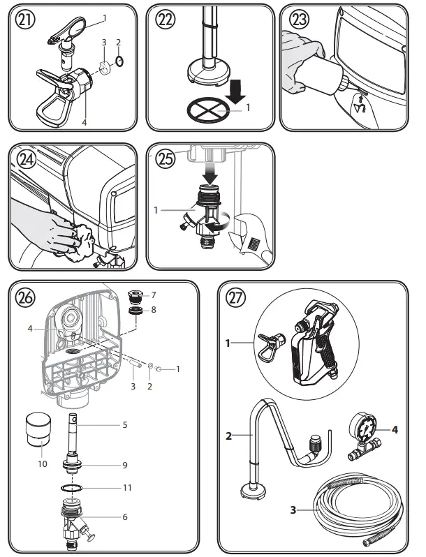
- Remove the nozzle holder from the spray gun. (Fig. 18)
- Put the suction hose and return flow pipe into a container full of water or a suitable cleaning solution.
- Turn the switch to the SPRAY position and set maximum pressure.
- Hold the spray gun at the edge of an empty container. (Fig. 19)
 Danger Earth the gun when flushing with solvents using a metal container.
 - Release the gun and keep the trigger pressed until only clear liquid emerges from the gun.
- Switch the device off and remove the power plug.
- Turn the switch into the PRIME position (vertical).
- Pull the trigger to relieve the pressure.
- Secure the spray gun.
- Remove spray gun from the paint hose using adjustable wrenches.
- Unclip the top of the trigger guard (fig. 20, 1) from the gun head.
- Using the bottom of the trigger guard as a wrench, loosen and remove the handle assembly (fig. 20, 2) from the gun head.
- Remove the gun filter (fig. 20, 3). Clean it and the nozzle with a soft brush and a suitable detergent.
- Remove the nozzle (1), plain washer (2) and mounting (3) from the nozzle holder (4) and clean all parts thoroughly.(Fig.21)
- Replace the cleaned filter (fig. 20, 3) in the gun housing with the conical side forwards and screw the gun housing to the spray gun again.
- Replace the mounting and the plain washer in the nozzle holder. Screw the nozzle holder onto the gun.
- Detach the suction hose from the basic unit.
- Disconnect the return line by pushing the blue lock ring upwards and pulling the hose downwards at the same time.
- Wipe off the exteriors of both hoses.
- Carefully remove the filter disc (fig. 22, 1) from the suction filter using pliers.
- Clean the filter disk thoroughly under running water.
- Remove the high-pressure hose from the basic unit with a wrench.
- Pour approx. 60 ml oil into the pump as a preservative. (Fig. 23)
- Insert the power plug.
- Hold a cloth in front of the hose connection and switch the device on for approx. 5 seconds. (Fig. 24) This procedure preserves the pump
Taking Out of Operation and Cleaning
- Perform Pressure Relief Procedure.
- Secure the spray gun.
- Remove the nozzle holder from the spray gun. (Fig. 18)
- Put the suction hose and return flow pipe into a container full of water or a suitable cleaning solution.
- Turn the switch to the SPRAY position and set maximum pressure.
- Hold the spray gun at the edge of an empty container. (Fig. 19) Earth the gun when flushing with solvents using a metal container. Danger
- Release the gun and keep the trigger pressed until only clear liquid emerges from the gun.
- Switch the device off and remove the power plug.
- Turn the switch into the PRIME position (vertical).
- Pull the trigger to relieve the pressure.
- Secure the spray gun.
- Remove spray gun from the paint hose using adjustable wrenches.
- Unclip the top of the trigger guard (fig. 20, 1) from the gun head.
- Using the bottom of the trigger guard as a wrench, loosen and remove the handle assembly (fig. 20, 2) from the gun head.
- Remove the gun filter (fig. 20, 3). Clean it and the nozzle with a soft brush and a suitable detergent.
- Remove the nozzle (1), plain washer (2) and mounting (3) from the nozzle holder (4) and clean all parts thoroughly.(Fig.21)
- Replace the cleaned filter (fig. 20, 3) in the gun housing with the conical side forwards and screw the gun housing to the spray gun again.
- Replace the mounting and the plain washer in the nozzle holder. Screw the nozzle holder onto the gun.
- Detach the suction hose from the basic unit.
- Disconnect the return line by pushing the blue lock ring upwards and pulling the hose downwards at the same time.
- Wipe off the exteriors of both hoses.
- Carefully remove the filter disc (fig. 22, 1) from the suction filter using pliers.
- Clean the filter disk thoroughly under running water.
- Remove the high-pressure hose from the basic unit with a wrench.
- Pour approx. 60 ml oil into the pump as a preservative. (Fig. 23)
- Insert the power plug.
- Hold a cloth in front of the hose connection and switch the device on for approx. 5 seconds. (Fig. 24) This procedure preserves the pump.
Maintenance and repairs
- Remove the suction hose and return tube.
- Remove the inlet valve unit (fig. 25, 1) from the basic unit with an adjustable wrench. Visually inspect the inside and outside of the inlet valve assembly. Clean any paint residue with the appropriate cleaning solution
- Replace inlet valve assembly by screwing it into the sprayer.
b) Servicing the pump
| Repair kits (Fig. 26) | |
| Description | Order No. |
| Repair kit for piston pump (Pos. 5.6.7.8.9.10.11) | 2325 023 |
| Repair kit for seals (Pos. 8.9) | 2324 303 |
Always wear protective eyewear while servicing the pump. Be sure to follow the Pressure Relief Procedure when shutting the unit down for any purpose, including servicing or adjusting. After performing the Pressure Relief Procedure, be sure to unplug the unit before servicing or adjusting. Area must be free of solvents and paint fumes.
- Remove the suction hose and return tube.
- Remove the front cover and the 4 screws that secure it using a T20 Torx head driver.
- Remove the yoke screw (1) and washer (2) that secures the dowel pin (3). The dowel pin connects the yoke (4) to the piston (5).
- Using a pliers, pull the dowel pin out.
- Rotate the pump shaft so the piston is in the top-dead-center position. Press the yoke (4) against the top nut (7) with a screwdriver, for example. This is required to disassemble all the parts.
- Unscrew the inlet valve unit (6) from the basic unit.
- Remove the piston unit by pushing the piston (5) downwards.
- Check the piston (5) and the seal unit (9) for wear and tear and replace parts if necessary.
- Unscrew and remove the top nut (7) using an adjustable wrench.
- Remove the upper seal (8) by pushing against the seal. Be sure not to scratch the housing where the seals are located.
- Clean the area where the new seals are to be installed.
Assembly
- Lubricate the new top seal (8) with Separating Oil or light household oil and by hand place the seal (with the open side facing down) into the top port of the housing.
- Take the new top nut (7) and apply some lubricant to the threads. Place the top nut into the top of the housing and tighten with an adjustable wrench. This will drive the top seal into the correct position.
- Lubricate the piston (5) and the seal unit (9) as described for the upper seal. Install the piston and seal unit in the lower part of the housing.
- Insert the insertion tool (10) and turn it firmly into the respective position, ensuring that the piston and seal are installed correctly. Remove the insertion tool.
- Align the piston (5) with the yoke (4). Be careful not to damage the piston.
- Apply a bearing grease to the holes in the yoke where the dowel (3) is inserted.
- Install the dowel pin (3) to connect the yoke to the piston. The piston may have to be moved up or down to do this.
- Install the yoke screw (1) and washer (2) to secure the dowel pin.
- Install the new 0-ring (11) on the inlet valve assembly. lubricate with Separating Oil or light household oil. thread into the bottom (inlet) of the housing, and tighten with an adjustable wrench.
- Apply a few drops of Separating Oil or light household oil between the top nut (7) and piston (5). This will prolong the seal life.
- Install front cover and 4 screws.
| Spare Parts List (Fig. 27) | ||
| Pos. | Description | Order No. |
| 1 | Sourav gum assembly | 538040 |
| 2 | Suction hose and Return line | 2306606 |
| 3 | High-pressure hose 15 m yellow | 2390608 |
| 4 | Pressure fall | 2383995 |
| Accessories not included in the delivery | |
| Description | Order No. |
| Nozzle 211 (20° spray angle, 0,011-inch nozzle diameter) | 554211 |
| Nozzle 311 (30° spray angle, 0,011-inch nozzle diameter) | 554311 |
| Nozzle 411 (40° spray angle, 0,011-inch nozzle diameter) | 554411 |
| Nozzle 213 (20° spray angle, 0,013-inch nozzle diameter) | 554213 |
| Nozzle 313 (30° spray angle, 0,013-inch nozzle diameter) | 554313 |
| Nozzle 413 (40° spray angle. 0.013-inch nozzle diameter) | 554413 |
| Nozzle 415 (40° spray angle. 0.015-inch nozzle diameter) | 554415 |
| Nozzle 515 (50° spray angle, 0,015-inch nozzle diameter) | 554515 |
| Nozzle 615 (60° spray angle, 0,015-inch nozzle diameter) | 554615 |
| Nozzle 417 (40° spray angle, 0,017-inch nozzle diameter) | 554417 |
| Nozzle 517 (50° spray angle, 0,017-inch nozzle diameter) | 554517 |
| pozzle 617 (60° spray angle. 0.017-inch nozzle diameter) | 554617 |
| Nozzle 519 (50° spray angle. 0.019-inch nozzle diameter) | 554519 |
| Nozzle 619 (60° spray angle, 0,019-inch nozzle diameter) | 554619 |
| Filter. red (nozzle 211/311/411/2131313/413. 1 pack) | 34383 |
| Filter. red (nozzle 211/311/411/2131313/413. 10 oack) | 97022 |
| Filter. yellow (nozzle 4151515/615. 1 Pack) | 43235 |
| Filter. yellow (nozzle 4151515/615. 10 pack) | 97023 |
| Filter. white (nozzle 417/5171617/519/619. 1 Pack) | 34377 |
| Filter white (noMe 417/5171617/519/619 10 park) | 97024 |
| Gun extension (15 cm) | 556074 |
| Gun extension (30 cm) | 556075 |
| Gun extension (45 cm) | 556076 |
| Gun extension (60 cm) | 556077 |
| Gun extension with the sewable knee joint (100 cm) | 96015 |
| Gun extension with the sewable knee joint (200 cm) | 96016 |
| Gun extension with the sewable knee joint (300 cm) | 96017 |
| Inline Roller IR-100 | 345010 |
| High-pressure hose DN 4 mm. 7.5 m with stainless steel nipple | 9984573 |
| High-pressure hose DN 6 mm. 15 m for dispersion | 9984574 |
| High-pressure hose DN 6 mm. 30 m for dispersion | 9984575 |
| Double socket for coupling high-pressure hoses (1/4″ x 1/4″) | 34038 |
| Metex-Reuse: Reuse for pre-filtering of coating material in the vessel. Place the suction pipe in the reuse. Sieve package (5 pcs) for paint Sieve package (5 pcs) for dispersion | 34950 34952 34951 |
| Easy Glide (118 ml) | 508619 |
Further information about the WAGNER range of products for renovating is available at www.wagner-group.com
| Technical Data | |
| pimp type | Piston Mann |
| Power source | 230 V – 50 Hz |
| Power consumption | 800 W |
| Fusing | Only connect to sockets protected with an Fl fuse (16 A) |
| Protection class | I |
| Max spray pressure | 20 MPa (200 bar) |
| Max delivery rate | 1 9 I/min |
| Volume flow at 12 MPa (120 bar) with water | 1.6 I/min |
| Sound pressure lever | 75 dB (A) Uncertainty K= 4 db |
| Sound pressure output* | 88 dB (A) Uncertainty K= 4 db |
| Oscillation lever | < 2.5 m/s 2 Uncertainty K= 1.5 m/s 2 |
| Max temperature of the coating substance | 40°C |
| Max. nozzle size | 0.019 |
| Hose length | 15 m |
| Product dimensions | approx. 40 x 29 x 44 cm |
| Weight | approx 10 2 kn |
The specified oscillation level has been measured according to a standard test procedure and can be used to compare against electric tools.
The oscillation level is also for determining an initial assessment of the vibrational strain.
Attention! The vibration emission value can differ from the specified value when the electric tool is actually in use, depending on how the electric tool is used. It is necessary to specify safety measures to protect the operating personnel. These measures are based on an estimated shutdown during the actual conditions of use (all parts of the operating cycle are taken into consideration here, for example, periods when the electric tool is switched off, and, when it is switched on but running without any load).
Environmental protection
Important Note regarding Product Liability!
Correction of Malfunctions
| Problem | Cause | Remedy |
| The sprayer does not start. 9‘ | •The sprayer is not plugged in. •The device is switched off. •The sprayer was turned off while still under pressure. •No voltage is coming from the wall plug. •The extension cord is damaged or has too low a capacity. •Device overheated •There is a problem with the motor | —• Plug the sprayer in. —• Turn the ON/OFF switch to ON. —• Perform pressure relief procedure and set selector switch back to SPRAY —• Properly test the power supply voltage. —• Replace the extension cord. —• Switch the device off, turn the selector switch to the PRIME position (vertical), remove the mains plug and allow device to cool down for min. 30 minutes. Eliminate the cause of overheating, e.g. covered ventilation slot. 1 —• Please contact Wagner Service |
| The spray device runs but does not suck up any paint when the selector switch is set to the PRIME position. | •The unit will not prime properly or has lost prime. •The paint bucket is empty or the suction tube is not totally immersed in the paint. •The suction tube is clogged. •The suction tube is loose at the inlet valve. •The inlet valve is stuck. •The inlet valve is wom or damaged. •The PRIME/SPRAY valve is plugged | —• Try to prime the unit again. —• Refill the bucket or immerse the suction tube in paint. —• Clean the suction tube. —• Tighten it securely. —0 Press the inlet valve pusher. If the problem is not solved, clean the inlet valve. —• Replace —0 Please contact Wagner Service |
| The sprayer draws up paint but the pressure drops when the gun is triggered. | •The spray nozzle is worn. •The inlet filter is clogged. •The gun filter is plugged. •The paint is too viscous or contaminated. •The inlet valve is worn or damaged. | —• Replace the spray nozzle with a new nozzle. —• Clean the inlet filter. —• Clean or replace the filter. Always keep extra filters on hand. —’ Thin or strain the paint. —. Replace |
| The spray gun leaks | •Internal parts of the gun are worn or dirty. | —• Please contact Wagner Service |
| The nozzle assembly leaks | •The nozzle was assembled incorrectly. •A seal is dirty. | —• Check the tip assembly and assemble property —0 Clean the seal. |
| The spray gun will not spray. | •The spray nozzle or the gun filter is plugged. •The spray tip is in the reverse position. | —• Clean the spray nozzle or gun filter. —• Put the nozzle in the forward position. |
The paint pattern is tailing | The paint is too viscous or contaminated. The spray nozzle or the gun filter is plugged. The spray nozzle is worn. •The inlet filter is clogged. •The gun filter is plugged. •The inlet valve is worn or damaged. | Thin or strain the paint. ➞ Clean the spray nozzle or gun filter. ➞ Replace the spray nozzle with a new nozzle. ➞ Clean the inlet filter. ➞ Clean or replace the filter. Always keep extra filters on hand. ➞ Replace |
- Scope of guarantee
All Wagner professional colour application devices (hereafter referred to as products) are carefully inspected, tested and are sub- ject to strict checks under Wagner quality assurance. Wagner exclusively issues extended guarantees to commercial or professional users (hereafter referred to as “customer”) who have purchased the product in an authorized specialist shop, and which relate to the products listed for that customer on the Internet under www.wagner-group.com/profi-guarantee.
The buyer’s claim for liability for defects from the purchase agreement with the seller as well as statutory rights are not impaired by this guarantee.
We provide a guarantee in that we decide whether to replace or repair the product or individual parts, or take the device back and reimburse the purchase price. The costs for materials and working hours are our responsibility. Replaced products or parts become our property. - Guarantee period and registration
The guarantee period amounts to 36 months. For industrial use or equal wear, such as shift operations in particular, or in the event of rentals it amounts to 12 months.
Systems driven by petrol or air are also guaranteed for a 12-month period. The guarantee period begins with the day of delivery by the authorized specialist shop. The date on the original purchase document is authoritative.
For all products bought in authorized specialist shops from 01.02.2009, the guarantee period is extended to 24 months providing the buyer of these devices registers in accordance with the following conditions within 4 weeks of the day of delivery by the authorized specialist shop.
Registration can be completed on the Internet under www.wagner-group.com/profi-guarantee.
The guarantee certificate is valid as confirmation, as is the original purchase document that carries the date of the purchase. Registration is only possible if the buyer is in agreement with having the data being stored that is entered during registration. When services are carried out under guarantee the guarantee period for the product is neither extended nor renewed. Once the guarantee period has expired, claims made against the guarantee or from the guarantee can no longer be enforced. - Handling If defects can be seen in the materials, processing or performance of the device during the guarantee period, guarantee claims must be made immediately, or at the latest within a period of 2 weeks. The authorized specialist shop that delivered the device is entitled to accept guarantee claims. Guarantee claims may also be made to the service centers named in our operating instructions. The product has to be sent without charge or presented together- er with the original purchase document that includes details of the purchase date and the name of the product. In order to claim for an extension to the guarantee, the guarantee certificate must be included. The costs as well as the risk of loss or damage to the product in transit or by the center that accepts the guarantee claims or who delivers the repaired product are the responsibility of the customer.
- Exclusion of guarantee Guarantee claims cannot be considered – for parts that are subject to wear and tear due to use or other natural wear and tear, as well as defects in the product that are a result of natural wear and tear, or wear and tear due to use. This includes in particular cables, valves, packaging, jets, cylinders, pistons, means-carrying housing components, filters, pipes, seals, rotors, stators, etc. Damage due to wear and tear that is caused in particular by sanded coating materials, such as dispersions, plaster, putty, adhesives, glazes, quartz foundation.
- – in the event of errors in devices that are due to non-compliance with the operating instructions, unsuitable or unprofessional use incorrect assembly and/or commissioned by the buyer or by a third party, or utilization other than is intended, abnormal ambient conditions, unsuitable coating materials, unsuitable operating conditions, operation with the incorrect mains voltage supply/ frequency, over-operation or defective servicing or care and/or cleaning.
– for errors in the device that have been caused by using accessory parts, additional components or spare parts that are not original Wagner parts.
– for products to which modifications or additions have been carried out. – for products where the serial number has been removed or is illegible – for products to which attempts at repairs have been carried out by unauthorized persons. – for products with slight deviations from the target properties, which are negligible with regard to the value and usability of the device. – for products that have been partially or fully taken apart. - Additional regulations.
The above guarantees apply exclusively to products that have been bought by authorized specialist shops in the EU, CIS, Australia and are used within the reference country.
If the check shows that the case is not a guarantee case, repairs are carried out at the expense of the buyer. The above regulations manage the legal relationship to us concludingly. Additional claims, in particular for damages and losses of any type, which occur as a result of the product or its use, are excluded from the product liability act except with regard to the area of application. Claims for liability for defects to the specialist trader remain unaffected. German law applies to this guarantee. The contractual language is German. In the event that the meaning of the German and a foreign text of this guarantee deviate from one another, the meaning of the German text has priority.
J. Wagner GmbH
Division Professional Finishing
Otto Lilienthal Strasse 18
88677 Markdorf Federal Republic of Germany
Subject to modifications
Warning
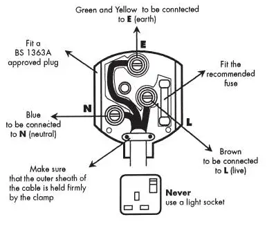
St the supply cord of this appliance is damaged, it must only be replaced by a repair shop appointed by the manufacturer. because special-purpose tools are required. The wires in this mains lead are colored in accordance with the following code:
green/yellow = earth blue = neutral brown = live
 As the colors of the wires in the mains lead of this appliance may not correspond with the colored markings identifying the terminals in your plug, proceed as follows:
- The wire which is colored green and yellow must be connected to the terminal in the plug which is marked with the letter E or by the earth symbol or colored green or green and yellow
- The wire which is colored blue must be connected to the terminal which is marked with the letter N or colored black.
- The wire which is colored brown must be connected to the terminal which is marked with the letter L or colored brown.
- Should the molded plug have to be replaced, never re-use the defective plug This could result in an electric shock.
- Should it be necessary to exchange the fuse in the plug only use fuses approved by Amp fuses may be used.
- To ensure that the fuse and fuse carrier are correctly mounted please observe plug.
- After changing the fuse. always make sure that the fuse carrier is correctly inserted. Without the fuse carrier. it is not permissible to use the plug.
- The correct fuses and fuse carriers are available from your local electrical supplies stockist.
References
 WAGNER Group for industry, craftsmen & do-it-yourselfers | WAGNER
-
WAGNER Group for industry, craftsmen & do-it-yourselfers | WAGNER
-
WAGNER Group for industry, craftsmen & do-it-yourselfers | WAGNER
-
Contractor's supplies: WAGNER Surface Technology | WAGNER
-
Contractor's supplies: WAGNER Surface Technology | WAGNER
-
WAGNER 3+2 Professional Guarantee | Product registration


