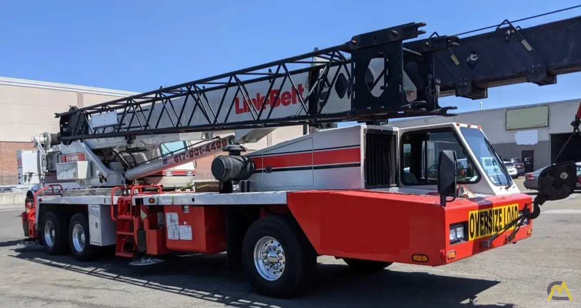
Crane Market HTC-8640 Telescopic Boom Truck Crane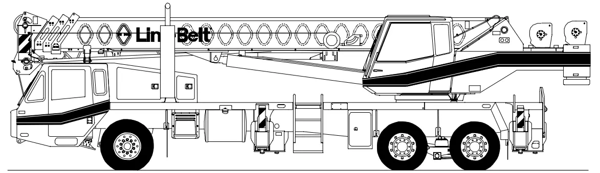
Upper Structure
Boom
Patented Design
- Boom side plates have diamond shaped impressions for superior strength to weight ratio and 100,000 psi (689.5mPa) steel angle chords for lateral stiffness
- Boom telescope sections are supported by top, bottom, and adjustable side wear shoes to prevent metal to metal contact
Boom
- 33 — 105 ft (10.06 —32.00m) four —section full power boom
- Two mode boom extension
- The basic mode is the full power, synchronized mode of telescoping all sections proportionally to 105 ft (32.00m)
- The exclusive “A —max” mode (or mode ‘A’) extends only the inner mid section to 57 ft (17.37m) offering increased capacities for in — close, maximum capacity picks
- Mechanical boom angle indicator
Boom Head
- Four 16.5 in (0.42m) root diameter nylon sheaves to handle up to eight parts of wire rope
- Easily removable wire rope guards
- Rope dead end lugs provided on each side of boom head
- Boom head designed for quick reeve of hook block
Boom Elevation
- One Link —Belt designed hydraulic cylinder with holding valve and bushing in each end
- Hand control for controlling boom elevation from — 3˚ to +78˚
Optional Auxiliary Lifting Sheave
- Single 16.5 in (0.42m) root diameter nylon sheave with removable wire rope guard, mounted to boom
- Use with one or two parts of line off the optional front winch
- Does not affect erection of fly or use of main head sheaves for multiple reeving
Optional
- 25 —ton (22.7mt) quick reeve hook block
- 40 —ton (36.3mt) quick reeve hook block
- 8.5 —ton (7.7mt) hook ball
- Boom floodlight
Fly
Optional
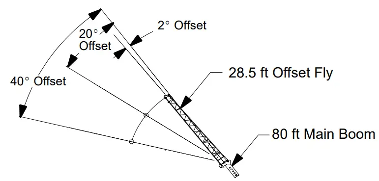
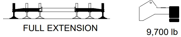
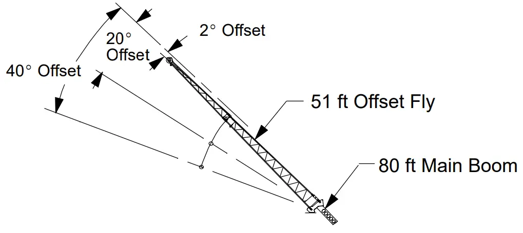
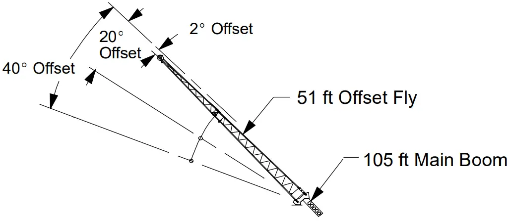
- 28.5 ft (8.69m) one —piece lattice fly, stowable, offsettable to 2˚, 20˚, and 40˚
- 28.5 — 51 ft (8.69 —15.54m) two —piece (bi —fold) fly, stowable, offset table to 2˚, 20˚, and 40˚
Cab and Controls
Environmental Ultra —Cabt S Laminated fibrous composite material; isolated from sound with acoustical fabric insulation
- Windows are tinted and tempered safety glass
- Sliding rear and right side windows and swing —up roof window for maximum visibility and ventilation
- Slide —by —door opens to 3 ft (0.91m) width
- Six —way adjustable seat for maximum operator comfort
- Hand —held outrigger controls and sight level bubble located in cab
- Diesel cab heater
- Pull—out Cabwalkt S Circulating fan
- Audible swing alarm S Warning horn
- Fire extinguisher S Cup holder
- 12—volt accessory outlet S Sun screen
- Electric windshield wiper S Hand throttle
- Windshield washer S Mirrors
- Top hatch window wiper S Dome light
Optional
- Amber strobe light
- Amber rotating beacon
- Hydraulic heater
- Air conditioning
Controls Hydraulic controls (joystick type) for:
- Swing
- Main winch
- Optional auxiliary winch
- Boom hoist
Foot controls for:
- Boom telescope
- Swing brake
- Engine throttle
Optional
- Auxiliary winch
- SIngle axis controls
Cab Instrumentation
Cornerpost —mounted gauges for:
- Hydraulic oil temperature
- Audio/Visual warning system
- Tachometer
- Oil pressure
- Voltmeter
- Fuel
- Water temperature
Rated Capacity Limiter
- Microguard 434 Graphic audio —visual warning system built into dash with anti — two block and function limiters
Operating data available includes:
- Machine configuration.
- Boom length
- Boom angle
- Head height
- Radius of load
- Allowed load
- Actual load
- % of allowed load
Presettable alarms include:
- Maximum and minimum boom angles
- Maximum tip height
- Maximum boom length
- Swing left/right positions
- Operator defined area alarm is standard
- Anti —two block weight designed for quick reeve of hook block
Optional
- Internal RCL light bar: Visually informs operator when crane is approaching maximum load capacity with a series of three lights; green, yellow, and red
- External RCL light bar: Visually informs ground crew when crane is approaching maximum load capacity kickouts and presettable alarms with a series of three lights; green, yellow, and red
Swing
- Bi —directional hydraulic swing motor mounted to a planetary reducer for 360_ continuous smooth swing at 2.8 rpm
- Swing park brake — 360˚, electric over hydraulic (spring applied, hydraulic released) multi —disc brake mounted on the speed reducer. Operated by toggle switch in overhead control console.
- Swing brake — 360˚, foot operated, hydraulic applied disc brake mounted on the speed reducer
- Swing lock — Standard; two position travel lock operated from the operator’s cab
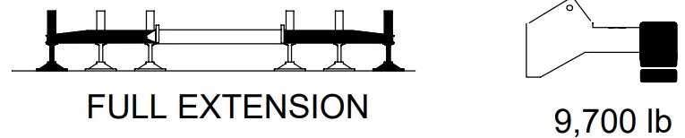
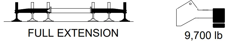
- Counterweight
- Standard — Bolted to upper structure frame. 9,700 lb (4 400kg) consisting of 4,700 lb (2 132kg) base counterweight and 5,000 lb (2 268kg) of removable counterweights.
Optional
- 360˚ swing lock. Meets New York City requirements.
Hydraulic System
Main Pump
- One gear pump with a total of four sections
- Combined pump capacity of 131 gpm (488Lpm)
- Powered by carrier engine through power take —off (PTO)
- Spline type pump disconnect, mechanically activated pump disconnect engaged/ disengaged from carrier cab
- Maximum system operating pressure is 3,350 psi (23 098kPa)
- O — ring face seals technology used throughout with hydraulic oil cooler standard
Steering / Fifth Outrigger Pump
- Single gear type pump, 6 gpm (23Lpm).
Powered by carrier engine through front gear housing - Max. pump operating pressure is 2,000 psi (13 790kPa). Reservoir — 131 gal (507.2L) capacity. One diffuser for deaeration.
Filtration
- One 10 —micron filter located inside hydraulic reservoir
- Accessible for easy replacement
Control valves
- Five separate pilot operated control valves allow simultaneous operation of all crane functions
Load Hoist System
Standard
- 2M main winch with grooved lagging
- Two —speed motor and automatic brake
- Power up/down mode of operation
- Bi —directional piston —type hydraulic motor driven through planetary reduction unit for positive control under all load conditions
- Asynchronous parallel double crossover grooved drums minimize rope harmonic motion
- Pressure compensated winch circuit provides balanced oil flow to both winches for smooth, simultaneous operation
- Rotation resistant wire rope
- Drum rotation indicators
Line Pulls and Speeds
- Maximum available line pull 13,010 lb (5 901kg) and maximum line speed of 480 fpm (146 m/min) on 10.63 in (0.27m) root diameter grooved drum
Optional
- 2M auxiliary winch with two —speed motor, automatic brake, and winch function lockout. Power up/down modes
- Hoist drum cable followers
- Third wrap indicators
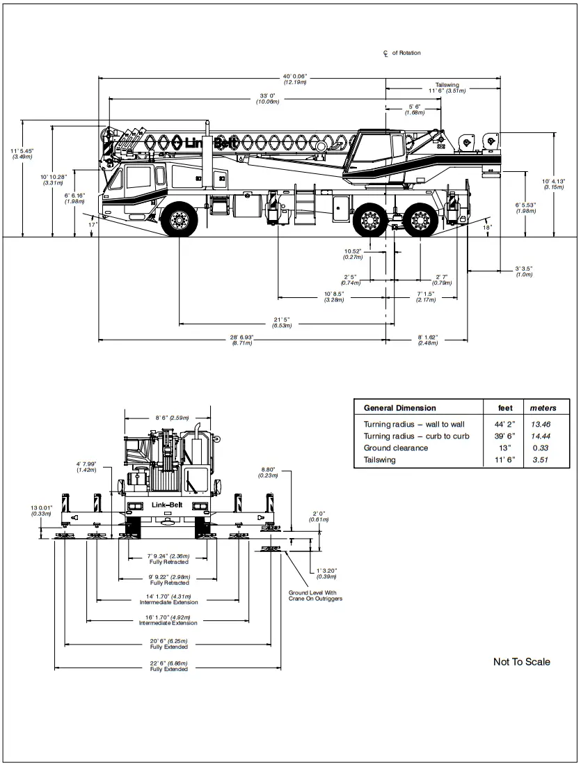
Carrier
Type
- 8 ft 6 in (2.59m) wide, 257 in (6.53m) wheelbase. 6 x 4 drive — standard.
Frame
- 100,000 psi (689.5MPa) steel, double walled construction with integral 100,000 psi steel outrigger boxes
Optional
- Carrier mounted storage boxes
- Pintle hook
- Electric and air connections for trailers
Axles
Front
- Single, 83.22 in (2.11m) track
Rear
- Tandem, 73.41 in (1.86m) track. 6.17 to 1.0 ratio with interaxle differential with lockout (6.64:1 ratio with automatic transmission)
Suspension
Front axle
- Leaf spring suspension
Rear axle
- Air — ride, bogie —beam type, suspension
Wheels
Standard
- Hub piloted aluminum disc
Tires
Standard Front
- 425/65R22.5 (Load range “L”) single tubeless radials
Standard Rear
- 12R22.5 (Load range “H”) dual tubeless radials
Brakes
Service
- Full air brakes on all wheel ends with automatic slack adjustors. Dual circuit with modulated emergency brakes.
- Front — 16.5 x 6 S —Cam brakes
- Rear — 16.5 x 7 S —Cam brakes
Parking/Emergency
- One spring set, air released chamber per rear axle end
- Parking brake applied with valve mounted on carrier dash
- Emergency brakes apply automatically when air drops below 40 psi (275.8kPa) in both systems
Steering
- Sheppard rack and pinion design
Optional
- Remote drive and steer
Transmission
Standard
- Eaton RTX — 11609B; 9 speeds forward, 2 reverse
Optional
- Automatic Allison MD 3066, 65:1 high, 3.49:1 low
Auxiliary
- Eaton 2A — 92, two speed — High: 1.0:1 Low: 2.3:1 (with automatic transmission only)
Electrical
- Two 12 —volt batteries provide 12 —volt starting. 160 — amp alternator
- 1,400 cold cranking amps available
- 12 —volt operating system
Lights
- Four dual beam sealed headlights
- Front, side, and rear directional signals
- Stop, tail and license plate lights
- Rear and side clearance lights
- Hazard warning lights
Outriggers
- Three position operation capability
- Four hydraulic, telescoping beam and jack outriggers
- Vertical jack cylinders equipped with integral holding valve
- Beams extend to 20 ft 6 in (6.25m) centerline —to — centerline and retract to within 8 ft 6 in (2.59m) overall width
- Equipped with stowable, lightweight 24 in (0.61m) diameter aluminum floats
- Standard fifth outrigger, 16 in (0.41m) self storing steel pad is operable from ground or operator’s cab
- Hand —held controls and sight level bubble located on carrier deck
Confined Area Lifting Capacities (CALCt) System
- The crane is operational in one of the three outriggers positions and operational in confined areas in two positions (intermediate and full retraction. The three outrigger positions are:
- Full extension — 20 ft 6 in (6.25m)
- Intermediate position — 14 ft 1.70 in (4.31m)
- Full retraction — 7 ft 9.24 in (2.36m)
- Capacities are available with the outrigger beams in the intermediate and full retraction positions
- When the outrigger position levers (located on the outrigger beams) are engaged, the operator can set the crane in the intermediate or full retraction outrigger position without having to leave the cab
Carrier Cab
- One —man cab of laminated fibrous composite material acoustical insulation with cloth covering
Equipped with:
- Air — ride, six —way adjustable operator’s seat
- Four —way adjustable tilting and lockable steering wheel
- Door and windows locks
- Left—hand and right—hand rear view mirrors
- Sliding right—hand and rear tinted windows
- Roll up/down left —hand tinted window
- Desiccant —type air dryer
- Steps to upper, lower cab and rear carrier
- 120 —volt electric engine block heate
- Back —up warning alarm
- Tow hooks and shackles
- Aluminum fenders with ground control outriggers
- Electric windshield wiper and washer
- Travel lights
- Horn
- Fire extinguisher
- Ashtray
- 36,000 BTU heater
- Defroster
- Dome light
- Cruise control
- Mud flaps
Optional
- Rotating Beacon
- Amber Strobe Light
- Air conditioning
Cab instrumentation
- Illuminated instrument panel speedometer
- Tachometer
- Hourmeter
- Fuel gauge
- Fuses
- Oil pressure gauge
- Odometer
- Turn signal indicator
- Voltmeter
- Water temperature gauge
- Front and rear air pressure gauges
- Audio/visual warning system
- Automotive type ignition
Carrier Speeds (Manual Transmission — Standard tires)
| Gear | High | Low | Hi Rev. | Lo Rev. | Low Rev. @700 rpm | Low @700 rpm | ||||||||
| 8 | 7 | 6 | 5 | 4 | 3 | 2 | 1 | Low | Rev. | Rev. | Low Rev. | Low | ||
| Ratio | 0.73 | 1.00 | 1.38 | 1.95 | 2.79 | 3.83 | 5.28 | 7.47 | 12.57 | 3.43 | 13.14 | 13.14 | 12.57 | |
| Speed | mph | 57.92 | 42.28 | 30.64 | 21.68 | 15.15 | 11.04 | 8.01 | 5.66 | 3.36 | 12.33 | 3.22 | 1.07 | 1.12 |
| km/hr | 93.42 | 68.19 | 49.42 | 35.00 | 24.44 | 17.81 | 12.92 | 9.13 | 5.42 | 19.89 | 5.42 | 1.72 | 1.64 | |
Engine
| Engine — standard | Cummins ISL 330 with Jake Brake |
| Cylinders — cycle | 6/ 4 |
| Bore | 4.49 in (114mm) |
| Stroke | 5.69 in (145mm) |
| Displacement | 540 cu. in. (8 849cm3) |
| Maximum brake hp. | 345 @ 1,900 rpm; 330 @ 2,100 rpm |
| Peak torque | 1,150 ft lb (1 559.2J) @ 1,300 — 1,400 rpm |
| Electric system | 12 —volt neg. ground / 12 volt starting |
| Fuel capacity | 75 gallons (284L) |
| Alternator | 12 volt, 160 amps |
| Crankcase capacity | 29 qt (28L) |
Axle Loads
| Base machine with standard 33 —105 ft (10. 6 –– 32. 0m) four section boom, 2M main winch with 2 —speed hoisting and power up/down, 450 ft (137m), 5/8 in (19mm) wire rope, 8 x 4, 8.5 ft (2.59m) carrier with Cummins ISL 330 Engine, 75 gal (284L) fuel, aluminum fenders, and 9,700 lb (4 400kg) counterweight. | G.V.W. ¡ | Upper Facing Front | ||||
| Front Axle | Rear Axle | |||||
| lb | kg | lb | kg | lb | kg | |
| 62,185 | 28 207 | 16,677 | 7 565 | 45,508 | 20 642 | |
| Left side carrier aluminum storage box | 57 | 26 | 14 | 6 | 43 | 20 |
| Right side carrier aluminum storage box | 57 | 26 | 14 | 6 | 43 | 20 |
| Six—speed automatic transmission and two—speed auxiliary transmission with engine brake | 576 | 261 | 223 | 101 | 353 | 160 |
| Air conditioning — Carrier cab | 124 | 56 | 135 | 61 | —11 | — 5 |
| Pintle hook w/air and electrical hook—ups | 32 | 15 | —9 | — 4 | 41 | 19 |
| Driver in carrier cab | 200 | 91 | 236 | 107 | —36 | —- 16 |
| Cab heater assembly (hydraulic) | 110 | 50 | —8 | —- 4 | 118 | 5 |
| Air conditioning — Operator cab | 315 | 143 | —35 | — 16 | 350 | 159 |
| Rear winch roller | 77 | 35 | —31 | — 14 | 108 | 49 |
| Front winches with two speeds and 450 ft (137.2m) of wire rope | 312 | 141 | —93 | — 43 | 405 | 184 |
| Front winch roller | 77 | 35 | —22 | — 10 | 99 | 45 |
| Remove rear winch rope (450 ft) | —365 | — 166 | 161 | 73 | —526 | — 239 |
| Remove front winch rope (450 ft) | —365 | — 166 | 120 | 54 | —485 | — 220 |
| 360˚ Mechanical House Lock | 60 | 27 | —2 | — 1 | 62 | 28 |
| Fly brackets to boom base section for fly options | 116 | 53 | 62 | 28 | 54 | 24 |
| 28.5 ft (8.69m) offsettable fly w/ATB weight (stowed) 28.5 —51 ft (8.69 — 15.54m) offsettable fly w/ATB weight (stowed) | 1,184 1, 57 | 537 797 | 839 1, 41 | 381 518 | 345 616 | 156 279 |
| Floodlight to front of boom base section | 10 | 5 | 13 | 6 | —3 | — 1 |
| 25 —ton (22.7mt) hook block stowed behind bumper (3 —sheaves) | 670 | 304 | 784 | 356 | —114 | — 52 |
| 40 —ton (36.3mt) hook block stowed behind bumper (4 —sheaves) Hookball to front bumper | 780 360 | 354 163 | 913 421 | 414 191 | —133 —61 | — 60 — 28 |
| Auxiliary arm w/ATB switch to boomhead | 110 | 50 | 169 | 69 | —59 | — 20 |
Adjust gross vehicle weight & axle loading according to component weight.
Note: All weights are ¦ 3%
| Axle | Maximum Load @ 65 mph (105km/h) |
| Front Rear | 22,700 lb (10 297kg) — aluminum disc wheels 47,250 lb (21 432kg) — aluminum disc wheels |
![]() WARNING
WARNING
READ AND UNDERSTAND THE OPERATOR’S AND SAFETY MANUALS AND THE FOLLOWING INSTRUCTIONS AND RATED LIFTING CAPACITIES BEFORE OPERATING THE CRANE. OPERATION WHICH DOES NOT FOLLOW THESE INSTRUCTIONS MAY RESULT IN AN ACCIDENT
OPERATING INSTRUCTIONS
GENERAL:
- Rated lifting capacities in pounds as shown on lift charts pertain to this crane as originally manufactured and normally equipped. Modifications to the crane or use of optional equipment other than that specified can result in a reduction of capacity.
- Construction equipment can be dangerous if improperly operated or maintained. Operation and maintenance of this crane must be in compliance with the information in the Operator’s, Parts, and Safety Manuals supplied with this crane. If these manuals are missing, order replacements through the distributor.
- The operator and other personnel associated with this crane shall read and fully understand the latest applicable American National Standards ASME B30.5 safety standards for cranes.
- The rated lifting capacities are based on crane standing level on firm supporting surface.
SET UP:
- The crane shall be leveled on a firm supporting surface. Depending on the nature of the supporting surface, it may be necessary to have structural supports under the outrigger pontoons or tires to spread the load to a larger bearing surface.
- When making lifts on outriggers, all tires must be free of supporting surface. All outrigger beams must be extended to the same length; fully retracted, intermediate extended, or fully extended. The front bumper outrigger must be properly extended.
- When making lifts on tires, they must be inflated to the recommended pressure. (See Operation note 20 and Tire Inflation.)
- Before swinging boom to over side position on tires, boom sections must be fully retracted not exceeding a 72_ boom angle.
- For required parts of line, see Wire Rope Capacity and Winch Performance.
- Before setting up on intermediate outriggers, retracted outriggers, or tires, refer to Working Range Diagrams and rated lifting capacities to determine allowable crane configurations.
OPERATION:
- Rated lifting capacities at rated radius shall not be exceeded. Do not tip the crane to determine allowable loads. For concrete bucket operation, weight of bucket and load shall not exceed 80% of rated lifting capacities. For clamshell bucket operation, weight of bucket and bucket contents is restricted to a maximum weight of 6,000 pounds or 80% of rated lifting capacity, whichever is less. For magnet operation, weight of magnet and load is restricted to a maximum weight of 6,000 pounds or 80% of rated lifting capacity, whichever is less. For clamshell and magnet operation, maximum boom length is restricted to 50 ft and the boom angle is restricted to a minimum of 35 degrees. Lifts with either fly erected is prohibited for both clam and magnet operation.
- Rated lifting capacities shown on fully extended outriggers do not exceed 85% of the tipping loads.
Rated lifting capacities shown on intermediate extended or fully retracted outriggers are determined by the formula, rated load = (tipping load — 0.1 X load factor)/1.25. Rated lifting capacities shown on tires do not exceed 75% of the tipping loads. Tipping loads are determined by SAE crane stability test code J —765. - Rated lifting capacities in the shaded areas are based on structural strength or hydraulic limitations and have been tested to meet minimum requirements of SAE J —1063 cantilevered boom crane structures —method of test.
The rated lifting capacities in non —shaded areas are based on stability ratings. Some capacities are limited by a maximum obtainable 78_ boom angle. - Rated lifting capacities include the weight of the hook ball/block, slings, bucket, magnet and auxiliary lifting devices. Their weights must be subtracted from the listed rated capacity to obtain the net load which can be lifted. Rated lifting capacities include the deduct for either fly stowed on the base of the boom. For deducts of either fly erected, but not used, see Capacity Deductions For Auxiliary Load Handling Equipment.
- Rated lifting capacities are based on freely suspended loads. No attempt shall be made to move a load horizontally on the ground in any direction.
- Rated lifting capacities are for lift crane service only.
- Do not operate at radii or boom lengths (minimum or maximum) where capacities are not listed. At these positions, the crane can tip or cause boom failure.
- The maximum loads which can be telescoped are not definable because of variation in loadings and crane maintenance, but it is permissible to attempt retraction and extension within the limits of the applicable load rating chart.
- For main boom capacities when either boom length or radius or both are between values listed, proceed as follows:
- For boom lengths not listed, use rating for next longer boom length or next shorter boom length, whichever is smaller.
- For load radii not listed, use rating for next larger radius.
- The user shall operate at reduced ratings to allow for adverse job conditions, such as: soft or uneven ground, out of level conditions, wind, side loads, pendulum action, jerking or sudden stopping of loads, hazardous conditions, experience of personnel, traveling with loads, electrical wires, etc. Side load on boom or fly is dangerous and shall be avoided.
- Rated lifting capacities do not account for wind on suspended load or boom. Rated capacities and boom length shall be appropriately reduced as wind velocity approaches or exceeds 20 mph.
- When making lifts with auxiliary head machinery, the effective length of the boom increases by 2 ft.
- Power sections of boom must be extended in accordance with boom mode “A” or “B”. In boom mode “B” all power sections must be extended or retracted equally.
- The least stable rated working area depends on the configuration of the crane set up.
- Rated lifting capacities are based on correct reeving. Deduction must be made for excessive reeving. Any reeving over minimum required (see Wire Rope Capacity) is considered excessive and must be accounted for when making lifts. Use Working Range Diagram to estimate the extra feet of rope then deduct 1 lb. for each extra foot of wire rope before attempting to lift a load.
- The loaded boom angle combined with the boom length give only an approximation of the operating radius. The boom angle, before loading, should be greater to account for deflection. For main boom capacities, the loaded boom angle is for reference only. For fly capacities, the load radius is for reference only.
- For fly capacities with main boom length less than 105 ft and greater than 80 ft, the rated capacities are determined by the boom angle using the 105 ft boom and fly chart. For angles not shown use the next lower boom angle to determine the rated capacity.
- For fly capacities with main boom length less than 80 ft, the rated capacities are determined by the boom angle using the 80 ft boom and fly chart. For angles not shown use the next lower boom angle to determine the rated capacity.
- The 33 ft boom length structural lifting capacities are based on boom fully retracted. If the boom is not fully retracted, do not exceed capacities shown for the 40 ft boom length.
- Rated lifting capacities on tires depend on tire capacity, condition of tires, and tire air pressure. On tire capacities require lifting from main boom head only on a smooth and level surface. The boom must be centered over the rear of the crane with two position travel swing lock engaged and the load must be restrained from swinging. Rated lifting capacities on tires are limited to creep and 2.5 mph speed. For correct tire pressure, see Tire Inflation.
DEFINITIONS:
- Load Radius: Horizontal distance from a projection of the axis of rotation to the supporting surface, before loading, to the center of the vertical hoist line or tackle with load applied.
- Loaded Boom Angle: (° The angle between the boom base section and horizontal with freely suspended load at the rated radius.
- Working Area: Area measured in a circular arc about the center line of rotation as shown on the Working Area Diagram.
- Freely Suspended Load: Load hanging free with no direct external force applied except by the hoist line.
- Side Load: Horizontal side force applied to the lifted load either on the ground or in the air.
- No Load Stability Limit: The radius or boom angle beyond which it is not permitted to position the boom because the crane can overturn without any load on the hook.
- Load Factor: Load applied at the boom tip which gives the same moment effect as the boom mass.
- Creep: Crane movement not exceeding 200 ft in a 30 minute period and 1 mph maximum speed.
BOOM EXTENSION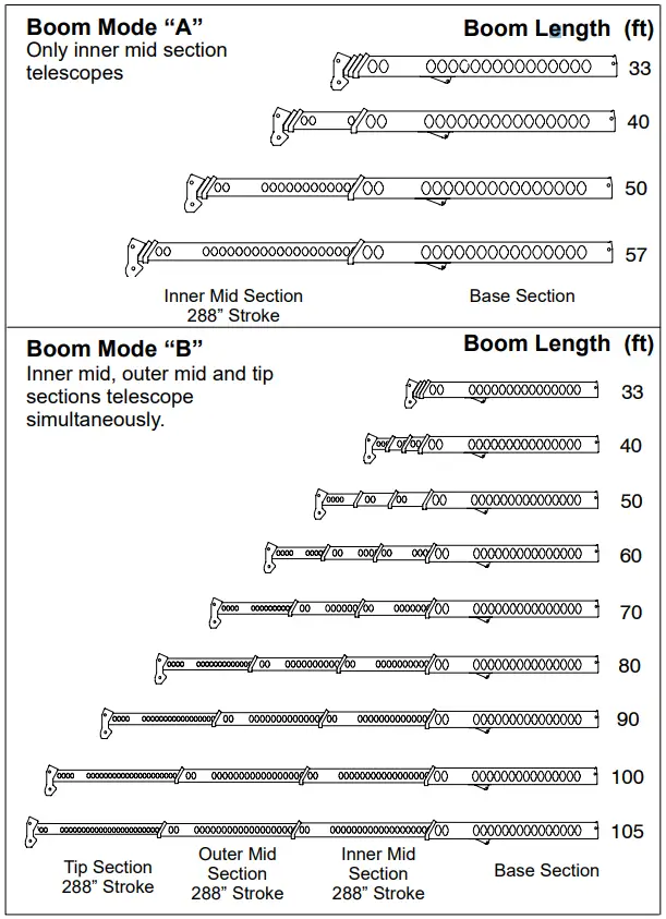
TIRE INFLATION
| Tire Size | Operation | Tire Pressure (psi) |
| 12R22.5 | Creep | 120 |
| 2.5 mph | 110 |
PONTOON LOADINGS
| Maximum Pontoon Load: | Maximum Pontoon Ground Bearing Pressure: |
| 61,750 lb | 137 psi |
CAPACITY DEDUCTIONS FOR AUXILIARY LOAD HANDLING EQUIPMENT
| Load Handling Equipment: | lb | |
| Auxiliary Head Attached | 100 | |
| 25– ton quick reeve 3– sheave hook block (see hook block for actual weight) | 670 | |
| 40– ton quick reeve 4– sheave hook block (see hook block for actual weight) | 780 | |
| 8.5– ton hook ball (see hook ball for actual weight) | 360 | |
| Lifting From Main Boom With: | lb | |
| 28.5 ft or 51 ft fly stowed on base (see operation note 4) | 0 | |
| 28.5 ft offset fly erected but not used | 2,600 | |
| 51 ft offset fly erected but not used | 4,800 | |
| Lifting From 28.5 ft Offset Fly With: | ||
| 22.5 ft fly tip erected but not used 22.5 ft fly tip stowed on 28.5 ft offset fly | PROHIBITED PROHIBITED | |
| Note: Capacity deductions are for Link– Belt supplied equipment only. | ||
WINCH PERFORMANCE
| Winch Line Pulls | Drum Rope Capacity (ft) | |||
| Wire Rope Layer | Two Speed Winch | |||
| Low Speed | High Speed | Layer | Total | |
| Available* (lb) | Available (lb) | |||
| 1 2 3 4 5 | 13,010 11,768 10,742 9,881 9,148 | 6,418 5,805 5,299 4,874 4,513 | 77 85 93 101 109 | 77 162 255 356 465 |
| *Maximum lifting capacity: Type RB Rope=9,080, Type ZB Rope=11,080 | ||||
WIRE ROPE CAPACITY
| Maximum Lifting Capacities Based On Wire Rope Strength | |||
| Parts of Line | 5/8” | 5/8” | Notes |
| Type RB | Type ZB | ||
| 1 | 9,080 | 11,080 | Capacities shown are in pounds and working loads must not exceed the ratings on the capacity charts in the Crane Rating Manual. Study Operator’s Manual for wire rope inspection procedures and single part of line applications. |
| 2 | 18,160 | 22,160 | |
| 3 4 | 27,240 36,320 | 33,240 44,320 | |
| 5 | 45,400 | 55,400 | |
| 6 | 54,480 | 66,480 | |
| 7 | 63,560 | 77,560 | |
| 8 | 72,640 | 88,640 | |
| 9 | 81,720 | y | |
| LBCE | DESCRIPTION | ||
| TYPE RB TYPE ZB | 18 X 19 Rotation Resistant – Compact Strand, High Strength Preformed, Right Regular Lay 36 X 7 Rotation Resistant – Extra Improved Plow Steel – Right Regular Lay | ||
WORKING AREAS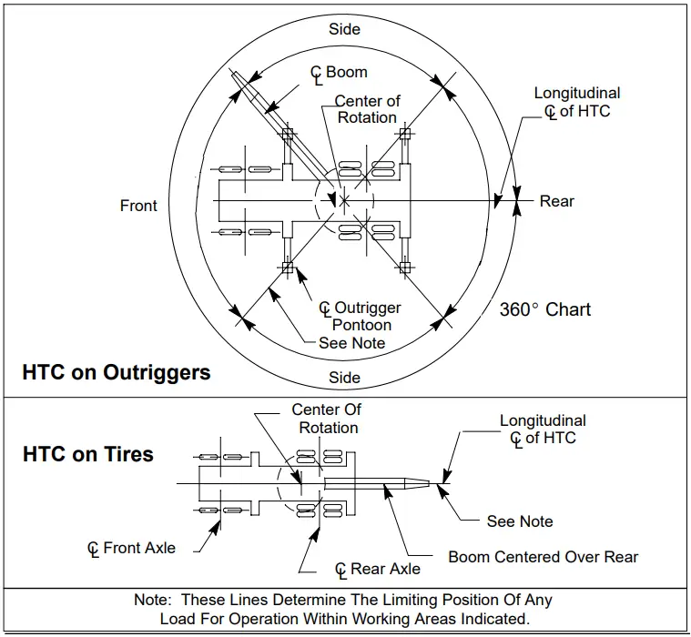
WORKING RANGE DIAGRAM
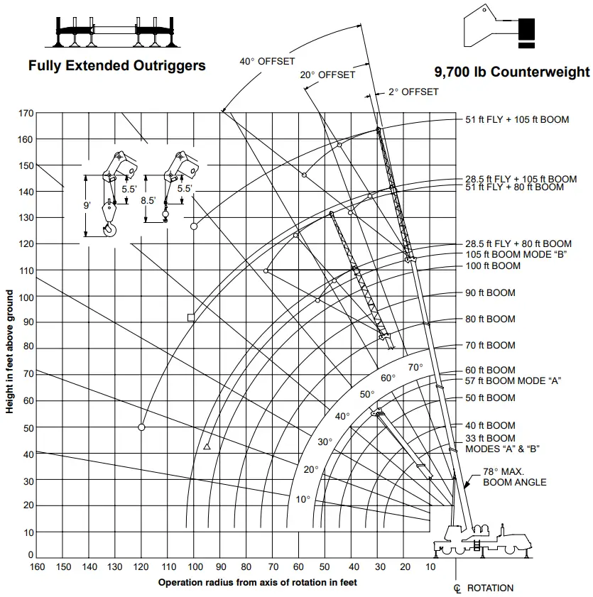
 Denotes Main Boom + 28.5’ Offset Fly —Boom Mode “B”
 Denotes Main Boom + 51’ Offset Fly —Boom Mode “B”
 Denotes Main Boom —Boom Mode “B”
Note: Boom and fly geometry shown are for unloaded condition and crane standing level on firm supporting surface. Boom deflection, subsequent radius and boom angle change must be accounted for when applying load to hook.
![]() WARNING Do Not Lower The Boom Below The Minimum Boom Angle For No Load Stability As Shown In The Lift Charts For
WARNING Do Not Lower The Boom Below The Minimum Boom Angle For No Load Stability As Shown In The Lift Charts For
The Boom Lengths Given. Loss Of Stability Will Occur Causing A Tipping Condition.
| Rated Lifting Capacities In Pounds Fully Extended Outriggers See Set Up Note 2 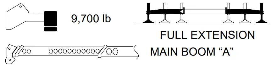 | |||||||
| Load Radius (ft) | 33 ft | 40 ft | |||||
| ( ° | 360° | Over Rear | ( ° | 360° | Over Rear | ||
| 9 10 12 15 20 25 30 | 68.0 66.0 62.0 55.5 43.5 26.5 | 80,000 72,300 65,500 55,600 42,200 | 80,000 72,300 65,500 55,600 42,200 | 70.5 67.5 62.5 54.0 44.0 31.0 | 72,300 65,200 55,300 41,900 | 72,300 65,200 55,300 41,900 | |
| 29,900 | 29,900 | 29,700 21,500 | 29,700 21,500 | ||||
| Min. Bm. Ang/Cap | 0 (27.5) | 18,400 | 18,400 | 0 (34.5) | 14,100 | 14,100 | |
| Load Radius (ft) | 50 ft | 57 ft | |||||
| ( ° | 360° | Over Rear | ( ° | 360° | Over Rear | ||
| 10 12 15 20 25 30 35 40 45 50 | 75.0 73.0 69.0 62.5 55.5 48.0 39.0 27.5 | 67,500 61,200 53,400 41,600 | 67,500 61,200 53,400 41,600 | 77.0 75.0 72.0 66.5 61.0 54.5 47.5 40.0 30.5 16.0 | 43,800 43,800 42,100 34,300 28,700 | 43,800 43,800 42,100 34,300 28,700 | |
| 29,300 21,300 16,100 12,400 | 29,300 21,300 16,100 12,400 | ||||||
| 21,100 16,000 12,300 9,600 7,600 | 21,100 16,000 12,300 9,600 7,600 | ||||||
| Min. Bm. Ang/Cap | 0 (44.5) | 9,300 | 9,300 | 0 (51.5) | 6,900 | 6,900 | |
Note: Refer To “Capacity Deductions For Auxiliary Load Handling Equipment”. (° Loaded Boom Angle In Degrees. ( ) Reference Radius For Min. Boom Angle Capacities (Shown in Parenthesis) Are In Feet.
| Rated Lifting Capacities In Pounds Fully Extended Outriggers See Set Up Note 2 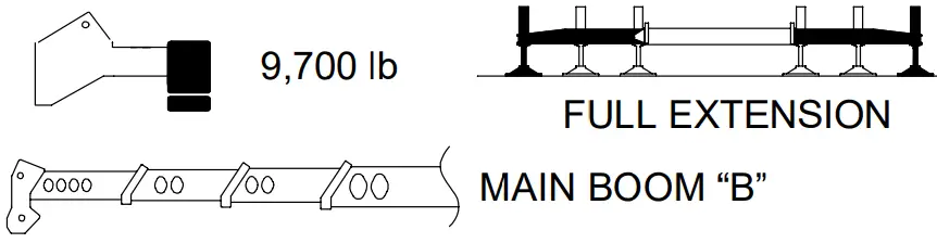 | ||||||||||
| Load Radius (ft) | 33 ft | 40 ft | 50 ft | |||||||
| 360° | Over Rear | 360° | Over Rear | 360° | Over Rear | |||||
| 9 10 12 15 20 25 30 35 40 | 68.0 66.0 62.0 55.5 43.5 26.5 | 80,000 72,300 65,500 55,600 42,200 | 80,000 72,300 65,500 55,600 42,200 | 70.5 67.5 62.5 54.0 43.5 31.0 | 35,000 35,000 35,000 35,000 | 35,000 35,000 35,000 35,000 | 74.5 72.5 68.5 62.5 55.5 47.5 39.0 27.5 | 35,000 35,000 35,000 35,000 | 35,000 35,000 35,000 35,000 | |
| 29,900 | 29,900 | 30,700 22,400 | 30,700 22,400 | 31,100 23,000 17,700 14,000 | 31,100 23,000 17,700 14,000 | |||||
| Min. Bm. Ang/Cap | 0 (27.5) | 18,400 | 18,400 | 0 (34.5) | 13,500 | 13,500 | 0 (44.5) | 9,200 | 9,200 | |
| Load Radius (ft) | 60 ft | 70 ft | 80 ft | |||||||
| 360° | Over Rear | 360° | Over Rear | 360° | Over Rear | |||||
| 10 12 15 20 25 30 35 40 45 50 55 60 65 70 | 77.5 75.5 72.5 67.5 62.5 56.5 50.5 43.5 35.5 25.0 | 35,000 35,000 35,000 35,000 | 35,000 35,000 35,000 35,000 | 75.5 71.5 67.0 62.5 57.5 52.0 46.5 40.0 33.0 23.0 | 35,000 35,000 | 35,000 35,000 | 74.5 71.0 67.0 62.5 58.5 53.5 49.0 43.5 37.5 31.0 22.0 | 30,700 26,400 22,900 | 30,700 26,400 22,900 | |
| 31,400 23,200 18,000 14,300 11,600 9,500 | 31,400 23,200 18,000 14,300 11,600 9,500 | 31,500 23,400 18,100 14,500 11,800 9,700 8,100 6,700 | 31,500 23,400 18,100 14,500 11,800 9,700 8,100 6,700 | |||||||
| 18,200 14,600 11,900 9,900 8,200 6,800 5,700 4,700 | 18,200 14,600 11,900 9,900 8,200 6,900 5,800 4,800 | |||||||||
| Min. Bm. Ang/Cap | 0 (54.5) | 6,500 | 6,500 | 0 (64.5) | 4,600 | 4,600 | 0 (74.5) | 3,300 | 3,300 | |
| Load Radius (ft) | 90 ft | 100 ft | 105 ft | |||||||
| 360° | Over Rear | 360° | Over Rear | 360° | Over Rear | |||||
| 20 25 30 35 40 45 50 55 60 65 70 75 80 85 90 95 | 77.0 73.5 70.0 66.5 63.0 59.0 55.0 50.5 46.0 41.5 35.5 29.5 21.0 | 27,400 23,500 20,500 18,100 | 27,400 23,500 20,500 18,100 | 76.0 73.0 70.0 66.5 63.0 59.5 56.0 52.5 48.5 44.0 39.5 34.0 28.0 20.0 | 21,000 18,700 16,500 14,600 | 21,000 18,700 16,500 14,600 | 76.5 74.0 71.0 68.0 65.0 61.5 58.5 55.0 51.0 47.0 43.0 38.5 33.5 27.5 19.5 | 17,500 17,500 15,700 13,800 | 17,500 17,500 15,700 13,800 | |
| 14,700 12,000 9,900 8,300 6,900 5,800 4,800 4,000 3,300 | 14,700 12,000 9,900 8,400 7,000 5,900 4,900 4,100 3,400 | |||||||||
| 12,000 10,000 8,400 7,000 5,800 4,900 4,100 3,400 2,800 2,200 | 12,000 10,000 8,400 7,100 6,000 5,000 4,200 3,500 2,900 2,400 | 12,100 10,000 8,400 7,000 5,900 4,900 4,100 3,400 2,800 2,200 1,800 | 12,100 10,000 8,400 7,100 6,000 5,100 4,300 3,600 3,000 2,400 2,000 | |||||||
| Min. Bm. Ang/Cap | 0 (84.5) | 2,300 | 2,300 | 0 (94.5) | 1,500 | 1,500 | 17.0 (96.3) | |||
| Rated Lifting Capacities In Pounds Fully Extended Outriggers See Set Up Note 2 | |||||||
| Load Radius (ft) | 2_ Offset | 20_ Offset | 40_ Offset | ||||
| ( ° | 360° | ( ° | 360° | ( ° | 360° | ||
| 25 30 35 40 45 50 55 60 65 70 75 80 85 90 95 100 | 77.0 74.5 72.0 69.0 66.0 63.0 60.0 57.0 53.5 49.5 45.5 41.5 37.0 31.5 25.5 16.5 | 15,200 13,900 11,900 11,000 10,300 9,600 8,900 |
76.0 73.0 70.0 67.0 64.0 61.0 57.5 54.0 50.0 45.5 41.0 35.5 28.5 18.5 |
8,700 8,100 7,600 7,100 6,700 6,400 6,000 5,800 |
77.0 74.0 71.0 67.5 64.0 60.5 57.0 52.5 48.0 42.5 |
6,100 5,800 5,600 5,400 5,300 5,100 5,000 4,900 | |
| 7,900 6,700 5,800 4,900 4,200 3,600 3,000 2,500 2,100 | |||||||
| 5,300 4,500 3,800 3,200 2,700 2,200 | |||||||
| 4,700 3,900 | |||||||
| Min. Bm. Ang/Cap. | 0 | 1,300 | 0 | 1,400 | 0 | 1,500 | |
| Rated Lifting Capacities In Pounds Fully Extended Outriggers See Set Up Note 2 | |||||||
| Load Radius (ft) | 2_ Offset | 20_ Offset | 40_ Offset | ||||
| ( ° | 360° | ( ° | 360° | ( ° | 360° | ||
| 35 40 45 50 55 60 65 70 75 80 85 90 95 100 105 | 76.5 74.5 72.5 70.0 67.5 65.5 63.0 60.5 57.5 54.5 51.5 48.5 45.0 41.5 38.0 | 9,000 9,000 8,800 7,900 7,200 6,600 6,100 | 78.0* 76.0 73.5 71.0 69.0 66.5 64.0 61.0 58.5 55.0 52.0 48.5 45.0 41.0 | 7,900 7,500 7,200 6,600 6,100 5,700 5,300 4,900 |
76.5 74.0 71.5 69.5 66.5 64.0 61.0 58.0 54.5 51.0 47.0 42.5 |
5,700 5,500 5,400 5,200 5,000 4,700 4,400 | |
| 5,500 4,700 4,000 3,300 2,800 2,300 1,900 1,500 | |||||||
| 4,400 3,700 3,100 2,600 2,100 1,700 | |||||||
| 4,000 3,300 2,800 2,300 1,800 | |||||||
| Rated Lifting Capacities In Pounds Fully Extended Outriggers See Set Up Note 2 | |||||||
| Load Radius (ft) | 2_ Offset | 20_ Offset | 40_ Offset | ||||
| ( ° | 360° | ( ° | 360° | ( ° | 360° | ||
| 35 40 45 50 55 60 65 70 75 80 85 90 95 100 105 110 115 120 | 76.0 74.0 71.5 69.5 67.0 64.5 62.0 59.5 57.0 54.0 51.0 48.0 45.0 41.5 37.5 33.0 28.0 22.0 | 7,400 6,700 6,100 5,600 5,100 4,700 4,300 4,000 3,800 3,500 3,300 3,100 2,900 |
78.0* 76.0 73.5 71.0 68.5 66.0 63.0 60.5 57.5 54.5 51.0 47.5 43.5 39.0 33.5 26.5 |
4,200 3,900 3,700 3,500 3,300 3,100 2,900 2,800 2,700 2,600 2,500 2,400 2,300 2,200 |
77.0 74.5 72.0 69.0 66.0 62.5 59.5 55.5 51.5 47.0 41.5 |
2,700 2,600 2,500 2,400 2,300 2,300 2,200 2,200 2,200 2,100 2,100 | |
| 2,700 2,300 2,000 1,600 1,400 | |||||||
| 1,800 1,500 | |||||||
| Rated Lifting Capacities In Pounds Fully Extended Outriggers See Set Up Note 2 | |||||||
| Load Radius (ft) | 2_ Offset | 20_ Offset | 40_ Offset | ||||
| ( ° | 360° | ( ° | 360° | ( ° | 360° | ||
| 40 45 50 55 60 65 70 75 80 85 90 95 100 105 110 115 120 | 77.5 75.5 74.0 72.0 70.5 68.5 66.5 64.5 62.0 60.0 58.0 55.5 53.0 50.0 | 5,800 5,700 5,400 5,100 4,800 4,500 4,200 3,900 3,600 3,300 3,000 |
77.5 75.5 73.5 71.5 69.5 67.5 65.5 63.5 61.0 58.5 56.0 53.5 50.5 |
3,700 3,500 3,400 3,200 3,100 2,900 2,800 2,700 2,600 2,500 2,300 |
76.5 74.5 72.5 70.5 68.0 65.5 63.0 60.5 57.5 54.5 51.0 |
2,500 2,400 2,400 2,300 2,300 2,200 2,200 2,200 2,100 1,900 | |
| 2,800 2,300 1,900 | |||||||
| 2,000 1,600 | |||||||
| 1,500 | |||||||
CUSTOMER SERVICE
Link–Belt Construction Equipment
Company Lexington, Kentucky
www.linkbelt.com
RLink–Belt is a registered trademark. Copyright 2004. We are constantly improving our products and therefore reserve the right to change designs and specifications.


