
crane 43030157 Push Up Bars

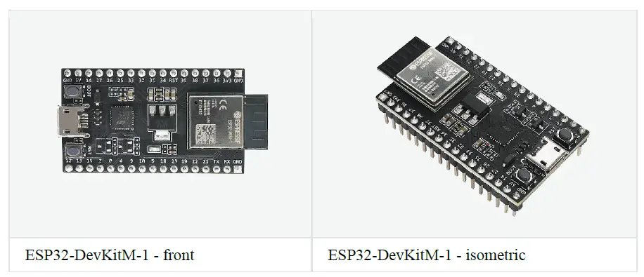
This user guide will help you get started with ESP32-DevKitM-1 and will also provide more in-depth information. ESP32-DevKitM-1 is an ESP32-MINI-1(1U)-based development board produced by Espressif. Most of the I/O pins are broken out to the pin headers on both sides for easy interfacing. Users can either connect peripherals with jumper wires or mount ESP32-DevKitM-1 on a breadboard.
The document consists of the following major sections:
- Getting started: Provides an overview of the ESP32-DevKitM-1 and hardware/software setup instructions to get started.
- Hardware reference: Provides more detailed information about the ESP32- DevKitM-1’s hardware.
- Related Documents: Gives links to related documentation.
Getting Started
This section describes how to get started with ESP32-DevKitM-1. It begins with a few introductory sections about the ESP32-DevKitM-1, then Section Start Application Development provides instructions on how to do the initial hardware setup and then how to flash firmware onto the ESP32-DevKitM-1.
Overview
This is a small and convenient development board that features:
- ESP32-MINI-1, or ESP32-MINI-1U module
- A USB-to-serial programming interface that also provides power supply for the board
- pin headers
- pushbuttons for reset and activation of Firmware Download mode
- a few other components
Contents and Packaging
Retail orders
If you order a few samples, each ESP32-DevKitM-1 comes in an individual package in either the antistatic bag or any packaging depending on your retailer. For retail orders, please go to https://www.espressif.com/en/company/contact/buy-asample.
Wholesale Orders
If you order in bulk, the boards come in large cardboard boxes. For wholesale orders, please go to https://www.espressif.com/en/contact-us/salesquestions.
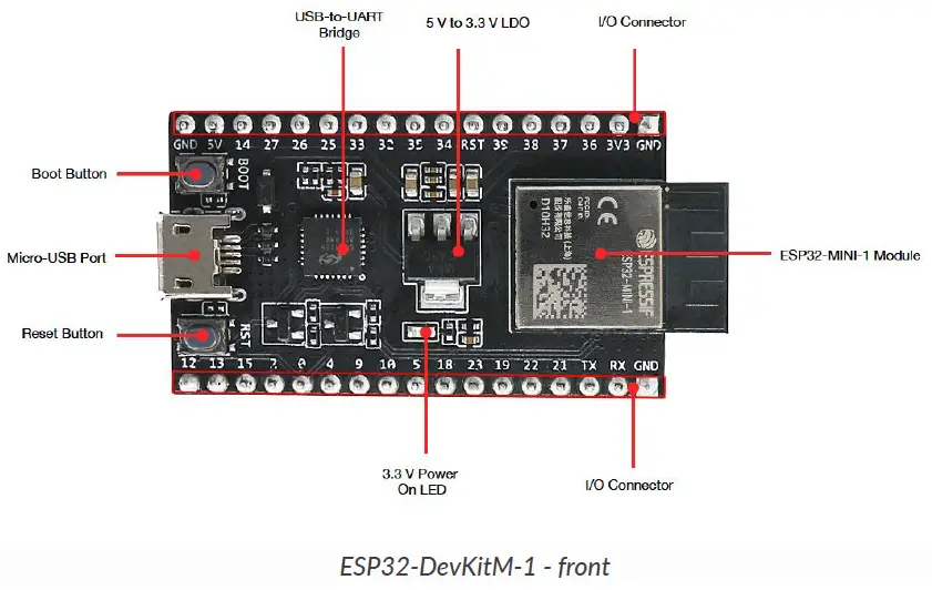
Description of Components
The following figure and the table below describe the key components, interfaces and controls of the ESP32-DevKitM-1 board. We take the board with an ESP32-MINI-1 module as an example in the following sections.
| Key Component | Description |
|
On-board module | ESP32-MINI-1 module or ESP32-MINI-1U module. ESP32-MINI-1 comes with an on-board PCB antenna. ESP32-MINI-1U comes with an external antenna connector. The two modules both have a 4 MB flash in chip package. For details, please see ESP32-MINI-1 & ESP32-MINI-1U Datasheet. |
| 5 V to 3.3 V LDO | Power regulator converts 5 V to 3.3 V. |
| Boot Button | Download button. Holding down Boot and then pressing Reset initiates Firmware Download mode for downloading firmware through the serial port. |
| Reset Button | Reset Button |
| Micro-USB Port | USB interface. Power supply for the board as well as the communication interface between a computer and the ESP32 chip. |
| USB-to-UART Bridge | Single USB-UART bridge chip provides transfer rates up to 3 Mbps. |
Start Application Development
Before powering up your ESP32-DevKitM-1, please make sure that it is in good condition with no obvious signs of damage.
Required Hardware
- ESP32-DevKitM-1
- USB 2.0 cable (Standard-A to Micro-B)
- Computer running Windows, Linux, or macOS
Software Setup
Please proceed to Get Started, where Section Installation Step by Step will quickly help you set up the development environment and then flash an application example onto your ESP32-DevKitM-1.
Attention
ESP32-DevKitM-1 is a board with a single core module, please enable single core mode (CONFIG_FREERTOS_UNICORE) in menuconfig before flashing your applications.
Hardware Reference
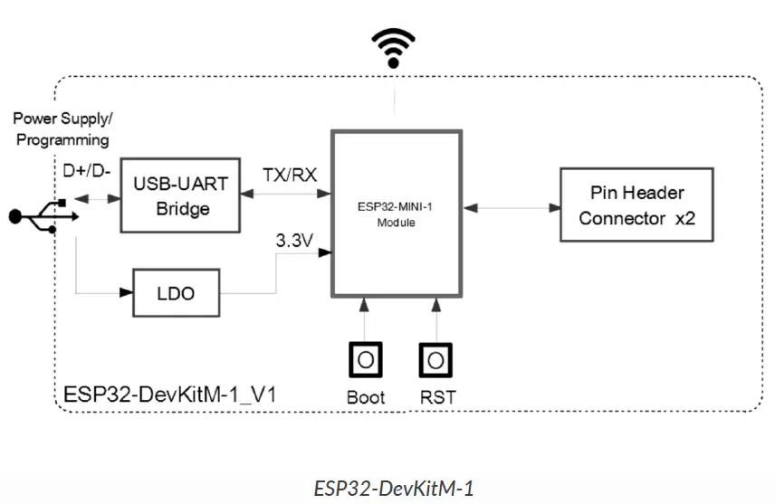
Block Diagram
A block diagram below shows the components of ESP32-DevKitM-1 and their interconnections.
Power Source Select
There are three mutually exclusive ways to provide power to the board:
- Micro USB port, default power supply
- 5V and GND header pins
- 3V3 and GND header pins
Warning
- The power supply must be provided using one and only one of the options above, otherwise the board and/or the power supply source can be damaged.
- Power supply by micro USB port is recommended.
Pin Descriptions
The table below provides the Name and Function of pins on both sides of the board. For peripheral pin configurations, please refer to ESP32 Datasheet.
| No. | Name | Type | Function |
| 1 | GND | P | Ground |
| 2 | 3V3 | P | 3.3 V power supply |
| 3 | I36 | I | GPIO36, ADC1_CH0, RTC_GPIO0 |
| 4 | I37 | I | GPIO37, ADC1_CH1, RTC_GPIO1 |
| 5 | I38 | I | GPIO38, ADC1_CH2, RTC_GPIO2 |
| 6 | I39 | I | GPIO39, ADC1_CH3, RTC_GPIO3 |
| 7 | RST | I | Reset; High: enable; Low: powers off |
| 8 | I34 | I | GPIO34, ADC1_CH6, RTC_GPIO4 |
| 9 | I35 | I | GPIO35, ADC1_CH7, RTC_GPIO5 |
| 10 | IO32 | I/O | GPIO32, XTAL_32K_P (32.768 kHz crystal oscillator input), ADC1_CH4, TOUCH9, RTC_GPIO9 |
| 11 | IO33 | I/O | GPIO33, XTAL_32K_N (32.768 kHz crystal oscillator output), ADC1_CH5, TOUCH8, RTC_GPIO8 |
| 12 | IO25 | I/O | GPIO25, DAC_1, ADC2_CH8, RTC_GPIO6, EMAC_RXD0 |
| 13 | IO26 | I/O | GPIO26, DAC_2, ADC2_CH9, RTC_GPIO7, EMAC_RXD1 |
| 14 | IO27 | I/O | GPIO27, ADC2_CH7, TOUCH7, RTC_GPIO17, EMAC_RX_DV |
| 15 | IO14 | I/O | GPIO14, ADC2_CH6, TOUCH6, RTC_GPIO16, MTMS, HSPICLK, HS2_CLK, SD_CLK, EMAC_TXD2 |
| 16 | 5V | P | 5 V power supply |
| 17 | IO12 | I/O | GPIO12, ADC2_CH5, TOUCH5, RTC_GPIO15, MTDI, HSPIQ, HS2_DATA2, SD_DATA2, EMAC_TXD3 |
| 18 | IO13 | I/O | GPIO13, ADC2_CH4, TOUCH4, RTC_GPIO14, MTCK, HSPID, HS2_DATA3, SD_DATA3, EMAC_RX_ER |
| 19 | IO15 | I/O | GPIO15, ADC2_CH3, TOUCH3, RTC_GPIO13, MTDO, HSPICS0, HS2_CMD, SD_CMD, EMAC_RXD3 |
| No. | Name | Type | Function |
| 20 | IO2 | I/O | GPIO2, ADC2_CH2, TOUCH2, RTC_GPIO12, HSPIWP, HS2_DATA0, SD_DATA0 |
| 21 | IO0 | I/O | GPIO0, ADC2_CH1, TOUCH1, RTC_GPIO11, CLK_OUT1, EMAC_TX_CLK |
| 22 | IO4 | I/O | GPIO4, ADC2_CH0, TOUCH0, RTC_GPIO10, HSPIHD, HS2_DATA1, SD_DATA1, EMAC_TX_ER |
| 23 | IO9 | I/O | GPIO9, HS1_DATA2, U1RXD, SD_DATA2 |
| 24 | IO10 | I/O | GPIO10, HS1_DATA3, U1TXD, SD_DATA3 |
| 25 | IO5 | I/O | GPIO5, HS1_DATA6, VSPICS0, EMAC_RX_CLK |
| 26 | IO18 | I/O | GPIO18, HS1_DATA7, VSPICLK |
| 27 | IO23 | I/O | GPIO23, HS1_STROBE, VSPID |
| 28 | IO19 | I/O | GPIO19, VSPIQ, U0CTS, EMAC_TXD0 |
| 29 | IO22 | I/O | GPIO22, VSPIWP, U0RTS, EMAC_TXD1 |
| 30 | IO21 | I/O | GPIO21, VSPIHD, EMAC_TX_EN |
| 31 | TXD0 | I/O | GPIO1, U0TXD, CLK_OUT3, EMAC_RXD2 |
| 32 | RXD0 | I/O | GPIO3, U0RXD, CLK_OUT2 |


