![]()
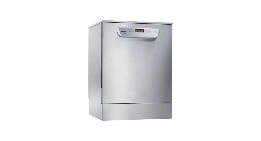
PG 8055 – PG 8099
Installation notes
For safe installation and commissioning of the dishwasher, please read the installation plan, the service documentation, and the operating instructions.
This installation plan includes the dimensions of the appliance, the technical data, and the requirements to be met on-site for the installation of the dishwasher.
Installation requirements
This dishwasher must be installed by an authorized technician in accordance with the installation instructions supplied. This dishwasher must be installed in accordance with all
applicable standards and guidelines, including legal requirements and health and safety regulations.
Electrical connection
Connection to the electrical supply should be in accordance with valid regulations and safety standards. The connection cable must be protected from the risk of thermal damage. We recommend connecting the dishwasher to the power supply via a suitable plug and socket as this will make it easier to carry out the electrical safety test during commissioning and after any service work. For hard-wired dishwashers, the connection should be made via a suitable mains switch with all-pole isolation, which in the off position ensures a 3 mm gap between all open contacts. Both the main switch and the socket must be easily accessible after installation. Faulty components must only be replaced by genuine Miele original spare parts. Only when these parts are fitted can the safety standards of the machine be guaranteed. If the connection cable is faulty it must only be replaced by a Miele-approved service technician to protect the user from danger.
Equipotential bonding and earthing
For added safety, the dishwasher should be protected with a residual current device with a trip current of 30 mA. Equipotential bonding should be carried out if required. The screw The connection point for equipotential bonding is located at the back of the dishwasher.
Water connection (without steam condenser)
The dishwasher can be plumbed into the cold water, hot water, and drainage points without a backflow protection device. The stopcock to the water supply must be easily accessible. The water supply to the dishwasher can be connected to either cold water or hot water.
Water connection (with steam condenser)
The machine can be plumbed into the cold water, hot water, demineralized water, and drainage points without a backflow protection device. Use the enclosed Y-piece to establish the water intake for the dishwasher (cold water) and the steam condenser. Alternatively, you can install an additional cold water line to connect the steam condenser. If hot water is not available, both intake hoses (cold and hot water) must be connected to the cold water supply via a Y-piece. The stopcock to the water supply must be easily accessible.
Environmental requirements
Condensate can build up in the area surrounding the dishwasher. Any furniture and fittings in the room must therefore be suitable for the purpose. If the machine is fitted under a suitable worktop, the panel supplied must be fitted above the door aperture to protect the worktop from moisture damage.
Connecting an external dispensing system
Up to two dispensing systems for liquid cleaning agents and rinsing agents can be connected to the back of the dishwasher. Machines with integrated dispensing systems have an external connection for rinsing agents.
Liquid agents: position of external containers
The liquid agent container for external dispensing must be positioned either next to or underneath the machine only. The container may be placed on the floor or in an adjacent cabinet. Do not place the container on top of or above the machine. Make sure that the dispensing hose does not get kinked or trapped.
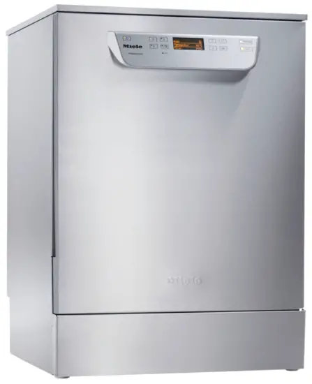
Freestanding appliance
PG 8055
PG 8056 (DOS)
PG 8057 TD (DOS)
PD 8058 (DOS)
PG 8059 (DOS)
PG 8096 (DOS)
PG 8099 (DOS)
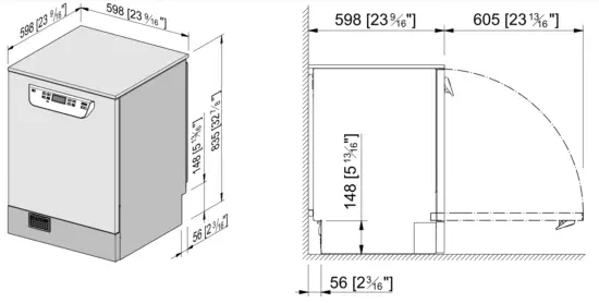
The front plinth area varies depending on the appliance type
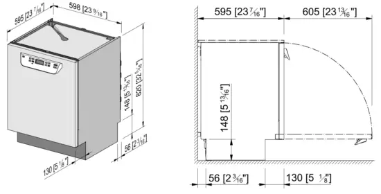
built-under appliance
PG 8055 U, PG 8056 U, PG 8061 U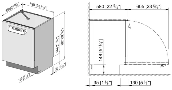 PG 8056 U DOS, PG 8096 U (DOS), PG 8099 U (DOS)
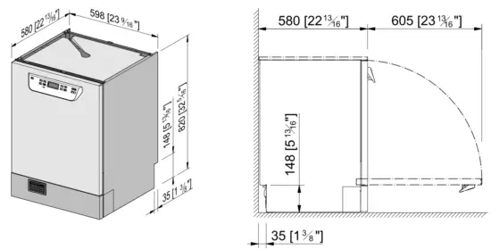 The front plinth area varies depending on the appliance type
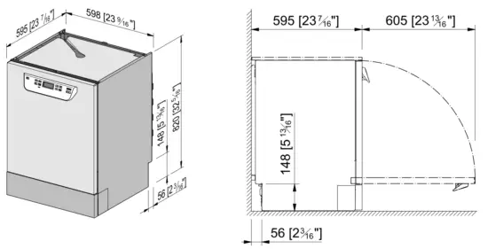
built-under appliance
PG 8057 TD U, PG 8058 U, PG 8059 U
PG 8057 TD U DOS, PG 8058 U DOS, PG 8059 U DOS
Connections on the back of the appliance
| PG 8055, KW only PG 8056 (DOS) PG 8061 PG 8096 (DOS) PG 8099 (DOS) | PG 8057 TD (DOS) PG 8058 (DOS) PG 8059 (DOS) * only PG 8058 (DOS) |
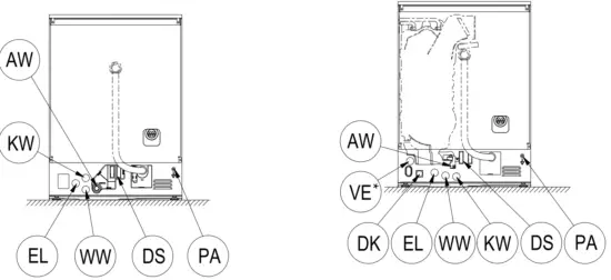
On-site connections
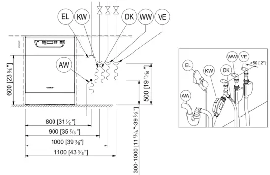
| NO | Coldwater | WW | Hot water |
| AW | Wastewater | EL | Electrical connection |
| DS | External dispensing, power supply connection | PA | Equipotential bonding |
| VE | DI water | DK | Coldwater for steam condenser |
Technical data
Electrical connection EU, CH, CN, RU, UA, KZ
| Voltage | 3N AC 400 V / 50 Hz | AC 230 V / 50 Hz |
| Power rating | 8.9 kW | 3.4 kW |
| Fuse rating | 3 x 16 A | 1 x 16 A |
| Mains connection cable, min. cross-section | 5 x 2.5 mm² | 3 x 1.5 mm² |
| Length of connection cable (H05(07)RN-F) | 1.7 m | 1.7 m |
Electrical connection BE, NO
| Voltage | 3 AC 230 V / 50 Hz | AC 230 V / 50 Hz |
| Power rating | 7.1 kW | 2.9 kW |
| Fuse rating | 3 x 20 A | 3 x 16 A |
| Mains connection cable, min. cross-section | 3 x 1.5 mm² | 3 x 1.5 mm² |
| Length of connection cable (H05(07)RN-F) | 1.7 m | 1.7 m |
Electrical connection AU
| Voltage | 3N AC 400 V / 50 Hz | AC 230 V / 50 Hz | AC 230 V / 50 Hz |
| Power rating | 8.9 kW | 5.9 kW | 2.9 kW |
| Fuse rating | 3 x 15–16 A | 1 x 30–32 A | 1 x 15–16 A |
| Mains connection cable, min. cross-section | 5 x 2.5 mm² | 3 x 4 mm² | 3 x 1.5 mm² |
| Connection cable length | 1.8 m | 1.9 m | 1.8 m |
Electrical connection US, CA
| Voltage | 2 AC 208 V 60 Hz | 3 AC 208 V 60 Hz | 3 AC 240 V 60 Hz | 2 AC 240 V 60 Hz |
| Power rating | 5.8 kW | 5.8 kW | 5.8 kW | 5.8 kW |
| Fuse rating | 2 pole x 30 A | 3 pole x 20 A | 3 pole x 20 A | 2 pole x 30 A |
| Mains connection cable, min. cross-section | 3 x AWG 10 (3 x 5.2 mm²) | 4 x AWG 12 (4 x 3.3 mm²) | 4 x AWG 12 (4 x 3.3 mm²) | 3 x AWG 10 (3 x 5.2 mm²) |
| Connection cable length | approx. 5’9” (1.8 m) | approx. 5’9” (1.8 m) | approx. 5’9” (1.8 m) | approx. 5’9” (1.8 m) |
| Electrical connection | NEMA L6-30 | NEMA L15-20 | NEMA L15-20 | NEMA L6-30 |
Coldwater
| Max. temperature | 20 °C | 68 °F |
| Max. permitted water hardness | 10714 mmol/l / 60 °dH | 63 gpg |
| Recommended flow pressure | 200 kPa | 29 psi |
| Minimum flow pressure with extended water intake | 100 kPa | 14.5 psi |
| Maximum flow pressure | 1000 kPa | 145 psi |
| Flow rate | 7.5 l/min | 2 gal/min |
| On-site threaded union in accordance with DIN 44991 (flat sealing) | 3/4 inch | 3/4 Male Garden Hose Thread |
| Inlet hose length | 1.7 m | 5′ 7″ |
| Length of the steam condenser inlet hose | 1.7 m | 5′ 7″ |
Hot water
| Max. temperature | 65 °C | 149 °F |
| Max. permitted water hardness | 10714 mmol/l / 60 °dH | 63 gpg |
| Recommended flow pressure | 200 a | 29 psi |
| Minimum flow pressure with extended water intake | 40 a | 5.8 psi |
| Maximum flow pressure | 1000 a | 145 psi |
| Flow rate | 7.5 l/min | 2 gal/min |
| On-site threaded union in accordance with DIN 44991 (flat sealing) | 3/4 inch | 3/4 Male Garden Hose Thread |
| Inlet hose length | 1.7 m | 5′ 7″ |
| Length of the steam condenser inlet hose | 1.7 m | 5′ 7″ |
Wastewater
| Max. wastewater temperature | 85 °C | 185 °F |
| Max. wastewater temperature PG 8057 TD | 93 °C | 200 °F |
| Drain hose length, standard | 1.5 m | 4′ 9″ |
| Drain hose, max. drainage length | 4.0 m | 13′ 1″ |
| Max. drain pump delivery head from the bottom edge of the machine | 1.0 m | 3′ 3″ |
| Max. transient flow rate | 16 l/min | 4.2 gal/min |
| On-site sleeve for drain hose (Ø x length) | 22 x 30 mm | 7/8″ x 1 3/16″ |
| Drain hose (Ø) | 22 mm | 7/8″ |
Machine data
| Machine feet height adjustment | 0 – 60 mm | 0 – 2 3/8″ |
| Max. net weight | 62.5 kg | 138 lbs |
| Max. floor load during operation | 1200 N | 1200 N |
| Min. access width, incl. transport pallet | 670 mm | 26 3/8″ |
| Min. access depth, incl. transport pallet | 740 mm | 29 3/8″ |
| Min. access height, incl. transport pallet | 920 mm | 36 1/4″ |
| Sound pressure LpA, washing and drying PG 8055, PG 8056, PG 8096, PG 8099 | 47 dB | 47 dB |
| Sound pressure LpA, washing and drying PG 8057 TD, PG 8058, PG 8059 | 45 dB | 45 dB |
Dispensing
Internal dispenser pump (DOS)
| Max. delivery head | 1.5 m | 4.9″ |
| Length of dispenser hose, back of the appliance to suction lance | ca. 1.8 m | ca. 5.9″ |
External dispenser pump
| Max. delivery head | 1.5 | 4.9″ |
| Length of dispenser hose, DOS module to suction lance | ca. 1.8 | ca. 5.9″ |
| Length of dispenser hose, back of the appliance to DOS module | ca. 2.8 | ca. 9.2″ |
| Length of power cable, back of the appliance to DOS module | ca. 2.8 | ca. 9.2 |
Heat dissipation rate to the installation site
| From heat radiation during operation | 0.35 kWh | 1194 BTU |
| From load items whilst unloading | 0.40 kWh | 1365 BTU |
Installation requirements
| Permitted ambient temperature | 5 – 40 °C | 40 – 104 °F |
| Max. relative humidity up to 31 °C | 80 % | 80 % |
| Rel. humidity, declining proportionally to 40 °C | 50 % | 50 % |
| Max. altitude above sea level up to | 2000 m | 2000 m |
![]()
Manufacturer:
Miele & Cie. KG
Carl-Miele-Straße 29
33332 Gütersloh
Germany
Manufacturing site:
Miele & Cie. KG
Mielestraße 2
33611 Bielefeld
Germany
Internet: www.miele.com/professional


