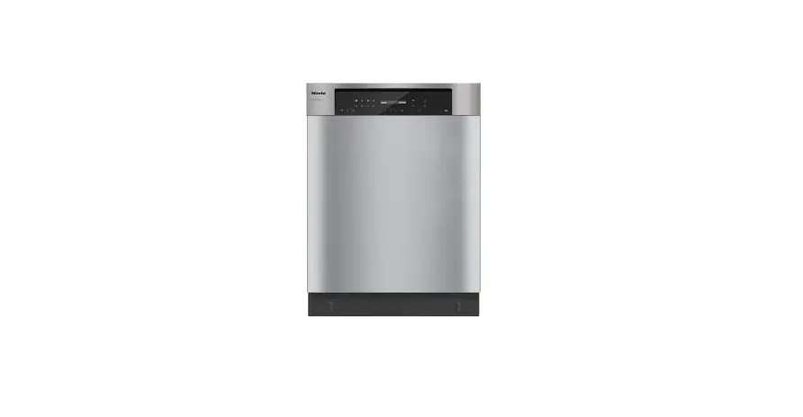
Miele PFD 101 U Brilliant Built Under Dishwasher Installation Guide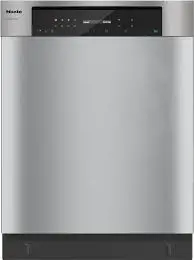
Installation notes
For safe installation and commissioning of the dishwasher please read the installation plan, the service documentation, the installation diagram, and the operating instructions.
This installation plan includes the dimensions of the appliance, the technical data, and the requirements to be met on site for the installation of the dishwasher.
Installation requirements
Installation and commissioning work should be performed by a qualified and trained service technician in accordance with local and national safety regulations.
Installation must comply with all local codes and regulations.
Surrounding area
Condensate can build up in the area surrounding the dishwasher. Any cabinetry and fittings in the room must, therefore, be suitable for this purpose.
Vapor-barrier film for built-in appliances
The vapor-barrier film supplied with the dishwasher protects the countertop from damage caused by steam when the door is opened. Attach the vapor-barrier film above the door, underneath the countertop.
Electrical connection
All work on the electrical connection should be carried out by Miele Service, an authorized Miele dealer or a qualified service technician.
Plug connection
The dishwasher should be connected to the electricity supply via an electrical socket outlet.
Hard-wired
If the dishwasher is hard-wired to the power supply, an appropriate circuit breaker for the circuit in compliance with local code must be used.
The electrical socket outlet and the power switch must be accessible after the appliance has been installed. This is to enable any servicing work.
The power cord must be protected from the risk of thermal damage.
Equipotential bonding and grounding
This machine must be grounded in accordance with local code.
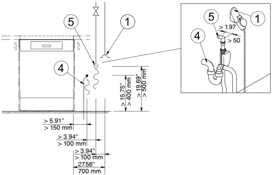
Water connection
The dishwasher must only be connected to fully vented pipework.
A brief increase in the water pressure can damage components of the dishwasher.
Water intake
The quality of the incoming water must comply with the requirements for drinking water in the country in which the dishwasher is being operated.
The dishwasher must be connected to the water supply in strict accordance with current local and national water authority regulations. It can be connected to cold or hot water supplies. Connecting the dishwasher to a hot water supply will reduce program cycle times.
For short program cycle times, a water pressure of at least 29 psi (200 kPa) is also required.
If this type of shut-off valve is not available, only a qualified installer may connect the dishwasher to the domestic water supply.
The shut-off valve should remain accessible once the dishwasher has been installed so that the water supply can be shut off whenever the appliance is not in use
Drainage
The dishwasher drainage hose should be connected to a separate on-site drain for the dishwasher only. If no separate drain is available, we recommend connecting it to a dual-chamber siphon. When using a drain loop additional backflow prevention is not required.
If the hose is to be directly connected to the drainage outlet on site, use the hose clip supplied with the dishwasher.
The on-site connector for the drain hose can be used for various hose diameters. If the connector extends more than 1″ (30 mm) into the drain hose, it must be shortened. Otherwise, the drain hose can become clogged.
Lay the drain hose so that it does not kink and is not being subjected to pressure or tugged.
If the on-site drain connection is situated lower than the guide path for the lower basket rollers in the open door, a siphoning effect during a program can cause the appliance to empty itself of water.
In this case, lay the drain hose with a bend in it so that its highest point is at least level with the guide path for the lower basket rollers.
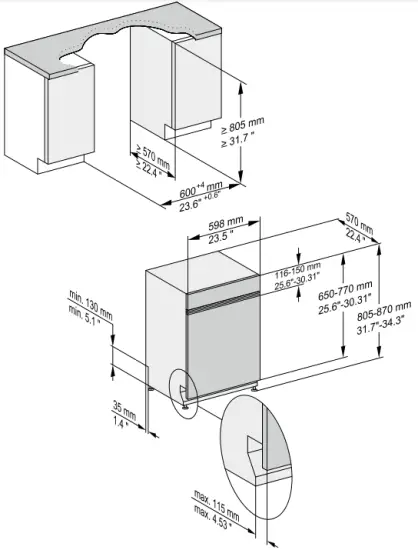
Appliance dimensions and installation dimensions
Undercounter appliance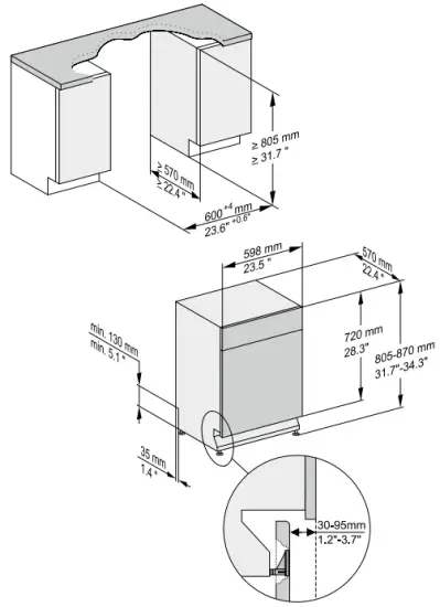
Built-in appliance PFD 102 i
Front panel dimensions
| Length | 19.7″–25.7″ | 500–654 mm |
| Thickness | 0.63″–0.79″ | 16–20 mm |
| Weight | 8.8–24.3 Ibs | 4–11 kg |
Fully integrated appliance PFD 104 SCV
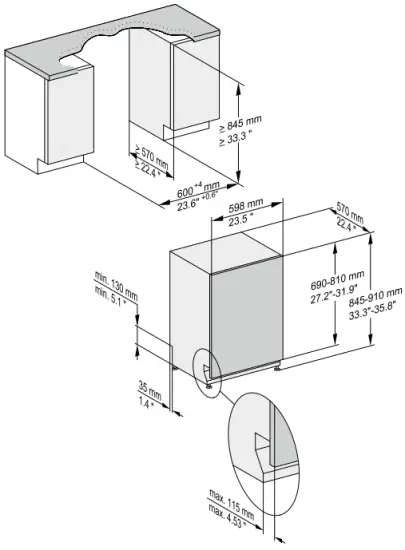
Front panel dimensions
| Length | 27.2″–31.9″ | 690–810 mm |
| Thickness | 0.63″–0.79″ | 16–20 mm |
| Weight | 11–26.5 lbs | 5–12 kg |
Connections
Connections on the back of the appliance
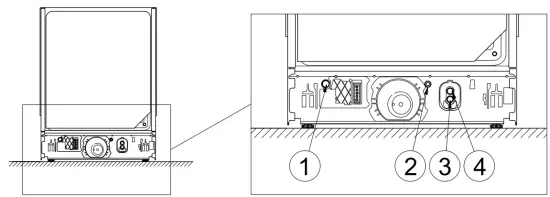
On-site connections
- Electrical connection
- Equipotential bonding and grounding
- Waste water
- Cold or hot water
Technical details
Dimensions and weights
| PFD 101 U | PFD 102 i | PFD 104 Vi | ||
| Height | [inches] | 32. | 32. | 33. |
| [mm] | 805 | 805 | 845 | |
| Height adjustment | [inches] | 3. | 3. | 3. |
| [mm] | 65 | 65 | 65 | |
| Width | [inches] | 24. | 24. | 24. |
| [mm] | 598 | 598 | 598 | |
| Depth | [inches] | 22. | 22. | 22. |
| [mm] | 570 | 570 | 570 | |
| Depth with door open | [inches] | 46. | 46. | 47. |
| [mm] | 1165 | 1165 | 1205 | |
| Max. toe-kick return | [inches] | 5. | 5. | 5. |
| [mm] | 115 | 115 | 115 | |
| Weight | [ibs] | 97 | 93. | 112 |
| [kg] | 44 | 42 | 51 | |
| Max. floor load | [N] | 1000 | 1000 | 1000 |
Emission levels
| PFD 101 U | PFD 102 i | PFD 104 Vi | ||
| Sound power level | [dB(A) re 1 pW] | 48 | 48 | 45 |
| Sound pressure level in the workplace | [dB(A)] | 35.1 | 35.1 | 31.4 |
Electrical connection
Standard electrical connection
| Voltage | AC 120 V |
| Frequency | 60 Hz |
| Fuse rating | 15 A |
| Plug | 5–15P NEMA |
| Power cord length | 5.6 ft/1.7 m |
| Power cord cross-section | 3 x AWG14 |
| Heat output | 1.3 kW |
| Total rated load | 1.4 kW |
Possible voltage variant
PFD 102 i and PFD 104 SCVi only
| Voltage | 2N AC 208–240 V | |
| Frequency | 60 Hz | |
| Fuse rating | 2 x 30 A | |
| Plug | 14–30P NEMA | |
| Power cord length | 5.6 ft/1.7 m | |
| Power cord cross-section | 4 x AWG10 | |
| Heat output | 3.5–3.8 kW | |
| Total rated load Water intake | 3.7–4 kW | |
| Max. water temperature | 140 °F | 60 °C |
| Max. water hardness | 66.5 mmol/l | |
| Max. water hardness | 36 °dH | |
| Water connection pressure | 5 – 1000 kPa | |
| On-site threaded connection (flat seal) | 3/4″ Hose thread | |
| Connection hose length | 4.9 ft | 1.5 m |
| Connection hose extension * | 4.9 ft | 1.5 m |
Drainage
| Max. water temperature | 180 °F | 82 °C |
| Drain hose length | 4.9 ft | 1.5 m |
| Max. drain hose length | 13 ft | 4 m |
| Max. drain height | 3.3 ft | 1 m |
| Max. transient flow rat | 10 l/min | |
| Hose inner diameter | 0.87″ | 22 mm |
| On-site hose sleeve ( x length) | 0.87″ x 1.18″ | 22 x 30 mm |
Operating conditions
| Ambient temperature | +41 – +104 °F | +5 – +40 °C | |
| Relative humidity: Up to 88 °F (31 °C), maximum | 80 % | ||
| Linear decreasing to 104 °F (40 °C) | 50 % | ||
| Max. altitude above sea level up to | 13,123 ft | 4,000 m |
Storage and transportation conditions
| Ambient temperatur | -4 – +140 °F | -20 – +60 °C |
| Relative humidity | 10–85 % | |
| Air pressure | 500–1060 hPa | |
Min. site access dimensions including transport pallet
| Height | 38.2″ | 970 mm |
| Width | 26.4″ | 670 mm |
| Depth | 26.4″ | 670 mm |


