![]()
Ultra-Low Power Bluetooth 5.0 BLE
Module
User Manual of JDY-23 Slave Bluetooth Module
JDY-23 Ultra Low Power Bluetooth 5.0 BLE Module
Version
| Version | Date | Description |
| V1.2 | 2018-08-07 | Release version |
Product Introduction
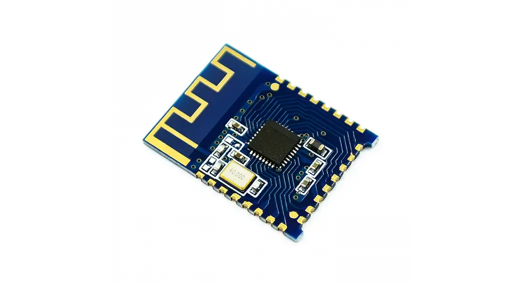
JDY-23 transparent transmission module is based on Bluetooth 5.0 protocol standard, with the working frequency range of 2.4GHz, the modulation mode of GFSK, the maximum transmission power of 4db, the maximum transmission distance of 60m. It adopts the imported original chip design, and supports the user to modify the device name, baud rate and other instructions through AT command, which is convenient, quick and flexible.
The JDY-23 Bluetooth module can realize the data transmission between the module and the mobile phone. By default, it can use BLE Bluetooth for product applications quickly without configuration.
Make BLE more convenient in product application
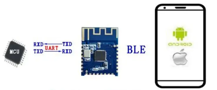
The module communicates with a mobile APP or Wechat applet
Debugging Tools
2.1 IOS test tool Apple store input JDY-LED Download Android test tools included in the package
2.2 Serial port tools (included in the data package)
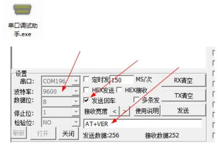
Serial port tool instructions for use
No input is required to send instructions using the serial port tool attached to the data package, selecting send return on the serial tool is equivalent to add \r\n at the end of the command.
Module Parameter Details
3.1 Module parameter
| JDY-23 Product Parameter | |
| Type | JDY-23 |
| Working frequency range | 2.4G |
| Transmit power | 4db(Max) |
| Communication interface | UART |
| Working voltage | 1.8V – 3.6V |
| Working temperature | -40℃ – 80℃ |
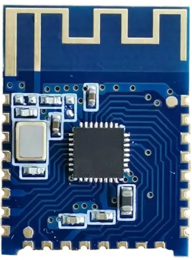
| Antenna | Built-in PCB antenna |
| Receiving sensitivity | -97dbm |
| Transmission distance | 60m |
| Master-slave support | Slave |
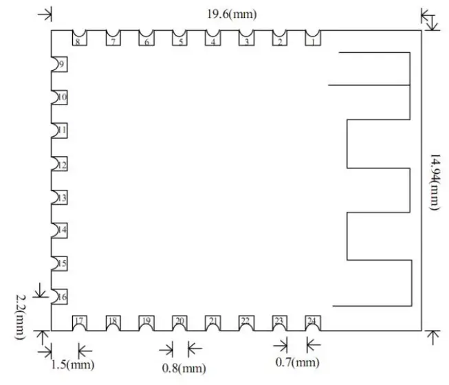
| Module size | 19.6 * 14.94 *1.8 mm(Length, width and height) |
| Bluetooth version | BLE 5.0(Compatible with BLE4.0、BLE4.2) |
| Wake upstate current | 800uA(Broadcast) |
| Light sleep state current | <50uA (Broadcast) |
| Deep sleep current | 9uA (No broadcast) |
| Instruction parameter saving | Parameter configuration power down data saved |
| SMT weldingtemperature | <260℃ |
| rf-TX/RX peak current | 5mA |
3.2 Working current
| Working mode | State | Average current | Note |
| Wake up serial port transparent transmission | Unconnected | 800uA | Generally, it is recommended to connect and communicate with APP, and broadcast should not be set too long, which will affect the connection time. It is recommended to be between 100 and 500mS. For fast |
| Deep no broadcast sleep | No broadcast | 3uA | |
| Light sleep withbroadcast | 100mS broadcast interval | 200uA | |
| 200mS broadcast | 80uA |
| Average power consumption | interval | connection and no power consumption requirement, you can set the broadcast interval to the shortest. | |
| 300mS broadcast interval | 50uA | ||
| 400mS broadcast interval | The following currents are lower | ||
| Wake up transparent transmission state | Connected | About 1mA | In the connected state, you can send AT command by pulling down PWRC pin or directly set working mode. For details, please refer to the AT+STARTEN command |
3.1 JDY-23 sleep mode description
| Sleep mode | Instruction | Function description |
| Power on wake up (Broadcast) | AT+STARTEN1 | Mode 1: Power on wake up. If the user needs to sleep, it can be controlled by the AT+SLEEP command and can waken up through PWRC pin low level |
| Power on sleep (Broadcast) | AT+STARTEN0 | Mode 0: in this mode, the power consumption is very low, the connection wake-up transparent transmission current is 900uA, and the disconnection current is below 200uA (the broadcast interval current can be set as low as 30uA). After the PWRC pin wakes up in this mode, if the serial port does not send data or is not connected within 10 seconds, it will automatically enter sleep again |
3.1 FAQ
| Question | Answer |
| 1: How to disconnect the Bluetooth connection of MCU in the connection state | In connection state, serial port sends “AT+DISC\r\n” to disconnect |
| 2: What is the current when the module wakes up and transparent transmission | About 1mA |
| 3: How much data can the serial port write at one time | No byte limit at 9600 baud rate |
| 4: After configuring parameter of serial port, does it need to restart to take effect | It is recommended to restart after setting the module parameter |
| 5: How to test the deep sleep current of the test module | It is recommended to connect VCC and GND pin to test current |
3.1 Factory common default parameter configuration
| No. | Function | Factory default parameters | Instruction |
| 1 | Serial port baud rate | 9600 | AT+BAUD4 |
| 2 | Sleep mode | Power on wake up | AT+STARTEN1 |
| 3 | Broadcast name | JDY-23 | AT+NAMEJDY-23 |
| 4 | Broadcast interval | 200MS | AT+ADVIN1 |
The above is the serial port transparent communication function. If there are special functions, please contact JDY technical support QQ: 2011811297
3.6 Pin definition
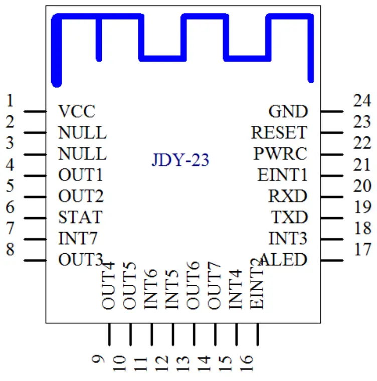
3.7 Pin function description
| Pin | Function | Description |
| 1 | VCC | Power supply(1.8-3.6V) |
| 2 | NULL | None |
| 3 | NULL | None |
| 4 | OUTPUT1 | IO1 output pin (supports APP to control high and low level |
| 5 | OUTPUT2 | IO2 output pin (supports APP to control high and low level |
| 6 | STAT | Connected status pin, connected high level, not connected low level |
| 7 | INPUT7/PWM4 | INPUT7 mode: input pin, the APP can read the status of this pin PWM mode: PWM4 output pin, APP can control PWM4 pulse width Default: INPUT7 mode |
| 8 | OUTPUT3 | IO3 output pin (supports APP to control high and low level |
| 9 | OUTPUT4 | IO4 output pin (supports APP to control high and low level |
| 10 | OUTPUT5 | IO5 output pin (supports APP to control high and low level |
| 11 | INPUT6/PWM3 | INPUT6 mode: input pin, the APP can read the status of this pin PWM mode: PWM3 output pin, APP can control PWM3 pulse width Default: INPUT6 mode |
| 12 | INPUT5/PWM2 | INPUT5 mode: input pin, the APP can read the status of this pin PWM mode: PWM2 output pin, APP can control PWM2 pulse width Default: INPUT5 mode |
| 13 | OUTPUT6 | IO6 output pin (supports APP to control high and low level |
| 14 | OUTPUT7 | IO7 output pin (supports APP to control high and low level |
| 15 | INPUT4 | INPUT4 mode: input pin, the APP can read the status of this pin |
| 16 | EINT2 | Interrupt input pin (press to actively send IO status to app in connection state |
| 17 | ALED | Broadcast indicator pin |
| 18 | INPUT3/PWM1 | INPUT3 mode: input pin, the APP can read the status of this pin PWM mode: PWM1 output pin, APP can control PWM1 pulse width Default: INPUT3 mode |
| 19 | TXD | Serial port output pin (TTL level |
| 20 | RXD | A serial port input pin (TTL level |
| 21 | EINT1 | Interrupt input pin (Press to actively send IO status to app in connection state |
| 22 | PWRC | Sleep wake-up pin, effective at low level In the connection state, the AT command can be sent by PWRC pin pull-down |
| 23 | RST | Reset pin, effective at low level |
| 24 | GND | Power ground |
and low levels (OUTPUT1, OUTPUT2, OUTPUT3, OUTPUT4, OUTPUT5, OUTPUT6, OUTPUT7) of modules, APP can read 7 input IO level states (PWRC, EINT1, EINT2, INPUT3, INPUT4, INPUT5, INPUT6, INPUT7) of the module, in which EINT1 and EINT2 are interrupt input pins and can actively report IO level state under connection state.
Serial Port AT Instruction Set
The AT command sent by the serial port of JDY-23 module must add \r\n
| No. | Instruction | Function | Master / slave | Default |
| 1 | AT+VER | Version number | S | JDY-23-V1.2 |
| 2 | AT+RST | Soft reset | S | – |
| 3 | AT+DISC | AT instruction disconnect | S | – |
| 4 | AT+STAT | 00 | ||
| 5 | AT+MAC | MAC address | S | – |
| 6 | AT+BAUD | Baud rate | S | 9600 |
| 7 | AT+SLEEP | Sleep | S | |
| 8 | AT+NAME | Broadcast name | S | JDY-23 |
| 9 | AT+STARTEN | Power on sleep or wake up | S | Power on wake up) |
| 10 | AT+ADVIN | Broadcast interval | S | 1(200mS) |
| 11 | AT+HOSTEN | Slave mode or BEACONworking mode | S | 0(slave) |
| 12 | AT+IBUUID | UUID of IBEACO | S | FDA50693A4E24F B1AFCFC6EB0764 7825 |
| 13 | AT+MAJOR | MAJOR of BEACON | S | 10 |
| 14 | AT+MINOR | MINOR of BEACON | S | 7 |
| 15 | AT+IBSING | Signal calibration at 1 meter | 0x32 | |
| 16 | AT+ALED | Broadcast LED indicator switch | 1 | |
| 17 | AT+IBPWR | The SING value of BEACON | S | 50 |
| 18 | AT+DEFAULT | Restore factory settings | S | – |
| 19 | AT+POWR | Transmit power | S | 8 |
| 20 | AT+ENLOG | Seria port output LOGswitch | S | 0 |
| 21 | AT+MTU | Set the serial port to send the number of packets to the APP | S | 1 |
| 22 | AT+BATT | Battery setting | S | 0 |
Note: green text indicates new functions, red bold parts need special attention.
AT Instruction Description
Special note: JDY-23 module serial port AT instruction needs to add end character \r\n
Query – version number
| Instruction | Response | Parameter |
| AT+VER | +VER: JDY-23-V1.2 | None |
Setting – soft reset
| Instruction | Response | Parameter |
| AT+VER | +VER: JDY-23-V1.2 | None |
Setting – disconnect
| Instruction | Response | Parameter |
| AT+DISC | +OK | None |
Note: under the connected state, directly send AT + DISC to disconnect, or pull the PWRC pin low to send AT command.
Query – connection status
| Instruction | Response | Parameter |
| AT+STAT | +STAT:<Param> | 00: indicates not connected 01: indicates connected |
Note: under the connected state, directly send AT + DISC to disconnect, or pull the PWRC pin low to send AT command
Setting / query – MAC address
| Instruction | Response | Parameter |
| AT+MAC<Param> | +OK | Param: (MAC address string) |
| AT+MAC | +MAC:<Param> |
Support AT instruction to modify MAC address, for example: AT+MAC112233445566\r\n
| Instruction | Response | Parameter |
| AT+BAUD<Param> | +OK | Param:(1-9) |
| AT+BAUD | +BAUD:<Param> | 0——11520 |
| 1——57600 | ||
| 2——38400 | ||
| 3——19200 | ||
| 4——9600 | ||
| 5——4800 | ||
| 6——2400 | ||
| Default: 4 |
Setting / query – sleep instruction
| Instruction | Response | Parameter |
| AT+SLEEP<Param> | +OK | Param: (1-2) 1: light sleep (with broadcast) 2: Deep sleep (no broadcast) |
| AT+SLEEP |
In the state of AT+STARTEN0, there is no need to send AT+SLEEP instruction, the module will automatically enter into SLEEP. The mobile phone will automatically wake p after connection, and enter into SLEEP after disconnection, PWRC pin falling edge wakes up. After wake up, the serial port has no data transmission or connection. After 15 seconds, it will automatically enter into sleep.
Setting / query – broadcast name
| Instruction | Response | Parameter |
| AT+NAME<Param> | +OK | Param: module Bluetooth name Maximum: 24 ytes Default name: JDY-23 |
| AT+NAME | +NAME:<Param> |
Setting/query – boot sleep and wake read and write
| Instruction | Response | Parameter |
| AT+STARTEN<Para m> | +OK | Param:(0-1) 1: power on to wake up, sleep can be controlled through AT SLEEP 0: power on sleep, connect wake-up, disconnect sleep |
| AT+STARTEN | +STARTEN:<Param > |
Setting / query – Broadcast interval
| Instruction | Response | Parameter |
| AT+ADVIN<Param> | +OK | Param:(0-9) |
| AT+ADVIN | +ADVIN:<Param> | 0:100ms |
| 1:200ms | ||
| 2:300ms | ||
| 3:400ms | ||
| 4:500ms | ||
| 5:600ms | ||
| 6:700ms | ||
| 7:800ms | ||
| 8:900ms | ||
| 9:10000ms | ||
| Default: 1 |
Setting/query – Module operation mode
| Instruction | Response | Parameter |
| AT+HOSTEN<Param> | +OK | Param:(0-3) 0: transparent transmission from slave (APP, applet) 3: Slave (iBeacon) mode Default: |
| AT+HOSTEN | +HOSTEN:<Param> |
Setting / query – iBeacon UUID
| Instruction | Response | Parameter |
| AT+IBUUID<Param> | +OK | Param:Hex UUID Default: FDA50693A4E24FB1AFCFC6EB076 47825 |
| AT+IBUUID | +IBUUID:<Param> |
Example: AT+IBUUID FDA50693A4E24FB1AFCFC6EB07647825
Setting/query – iBeacon Major
| Instruction | Response | Parameter |
| AT+MAJOR<Param> | +OK | Param:(0000-FFFF) Default: 000A |
| AT+MAJOR | + MAJOR:<Param> |
If the Major value is 10008, the AT instruction is: AT+MAJOR2718 \718 is 10008 hex data.
Setting/query – iBeacon Minor
| Instruction | Response | Parameter |
| AT+MINOR<Param> | +OK | Param:(0000-FFFF) Default: 0007 |
| AT+MINOR | +MINOR:<Param> |
If the Minor value is 10180, the AT instruction is: AT+MINOR27C4\27C4 is 10180 hex data
Setting /query – iBeacon IBSING
| Instruction | Response | Parameter |
| AT+IBSING<Param> | +OK | Param:(00-FF) Default: 40 |
| AT+IBSING | +IBSING:<Param> |
This parameter is applied to the signal calibration value of iBeacon at 1m.
Setting/query – ALED broadcast indicates LED switch
| Instruction | Response | Parameter |
| AT+ALED<Param> | +OK | Param:(0-1) 0: turn off the broadcast LED indicator 1: turn on the broadcast LED indicator Default: 1 |
| AT+ALED | +ALED:<Param> |
The broadcast indicator only works in AT+HOSTEN0 mode, and does not work in light sleep or try sleep mode
Restore factory configuration (restore to factory default configuration parameters)
| Instruction | Response | Parameter |
| AT+DEFAULT | +OK | None |
Setting/query – serial port output status information
| Instruction | Response | Parameter |
| AT+ENLOG<Param> | +OK | Param:(0-1) 0: serial port does not output (power on, connection, isconnection, c.) information 1: serial port output status information Default: 0 |
| AT+ENLOG | +ENLOG:<Param> |
Setting / query – MTU byte
| Instruction | Response | Parameter |
| AT+MTU<Param> | +OK | Param:(1-2)1: 20 byte 2: 128-byte Default: 1 |
| AT+MTU | +MTU:<Param> |
Setting – battery service charge
| Instruction | Response | Parameter |
| AT+BATT<Param> | +OK | Param:(0-100) 0: indicates the power is 0% 99: indicates the power is 99% Default: 0 |
| AT+BATT | +BATT:<Param> |
Mobile Terminal Instruction
6.1 APP UUID list
Service UUID:0xFFE0 (Service UUID Default 0xFFE0)
Feature UUID : 0xFFE1 For transparent transmission Default 0xFFE1
Attribute notify write: Feature UUID:0xFFE2 (For IO control Default 0xFFE2 Attribute write).
6.2 APP controls OUT output pin level (Characteristic FFE2
| IO port No. | Instruction(HEX | Function | Factory default level |
| OUT1 | E7F100 | Output low level | Low level |
| E7F101 | Output high level | ||
| OUT2 | E7F200 | Output low level | Low level |
| E7F201 | Output high level | ||
| OUT3 | E7F300 | Output low level | Low level |
| E7F301 | Output high level | ||
| OUT4 | E7F400 | Output low level | Low level |
| E7F401 | Output high level | ||
| OUT5 | E7F5100 | Output low level | Low level |
| E7F501 | Output high level | ||
| OUT6 | E7F600 | Output low level | Low level |
| E7F601 | Output high level | ||
| OUT7 | E7F700 | Output low level | Low level |
| E7F701 | Output high level | ||
| All OUTpin | E7FF01 | All OUT pin high | Low level |
| E7FF00 | All OUT pin low level |
6.3 APP reads INT pin level status
APP sends all int pin level status query commands (HEX to feature UUID: FFE2
App sends to feature FFE: E7A1
The module returns INT pin level status to APP: E7A20101010101010101 Format description, E7A2 is the data head.
The color corresponding to INT pin: PWRCEINT1EINT2INT3INT4INT5INT6INT7
6.4 INT pin is pressed to actively send data format to APP
Eint1 pin sends data format to APP: FC01010001
Eint2 pin sends data format to APP: FC01010001
JDY-23 Basic Application Wiring Diagram
7.1 JDY-23 and 3.3V MCU serial port transparent transmission wiring diagram
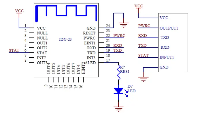
If low power consumption is not required for transparent transmission or disconnection command is not required in the connection state, the PWRC pin can be disconnected.
If low power consumption is not needed or connection status is not needed to be detected, it only needs four pins of VCC, GND, RXD and TXD to be connected.
MCU password verification instructions:
At present, JDY-23 does not add a Bluetooth connection password function. If you need to judge the connection password to avoid other people’s illegal connections, you can judge the password through the user’s MCU. After the user app connects to JDY-23, the user app sends the password to the user MCU. If the user APP does not receive the correct password from the APP within 3 seconds after the connection, the MCU will not receive any data from the APP. Only when the password is correct, can it start to receive the transparent data of the APP. If the correct password is not sent to the user MCU within 3 seconds, the MCU will pull down the PWRC pin, sending the AT+DISC command to the Bluetooth module, and immediately disconnect the Bluetooth module from the APP.
7.2 JDY-23 mobile phone APP controls OUT pin high and low level and reads INT pin level wiring diagram
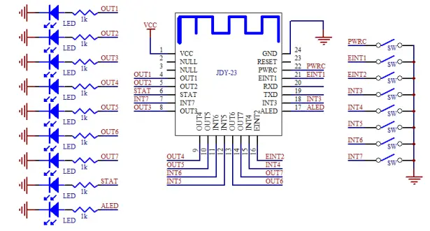 APP can control the high and low level of output pins from OUT1 to OUT7, and APP can read the level state of all input pins of EINT and INT, and EINT1 and EINT2 can actively report the level state in the module connection state.
FCC statement
This device complies with Part 15 of the FCC rules. Operation is subject to the following two conditions: 1) this device may not cause harmful interference, and 2) this device must accept any interference received, including interference that may cause undesired operation.
Note: This equipment has been tested and found to comply with the limits for a Class B digital device, pursuant to part 15 of the FCC Rules. These limits are designed to provide reasonable protection against harmful interference in a residential installation. This equipment generates uses and can radiate radio frequency energy and, if not installed and used in accordance with the instructions, may cause harmful interference to radio communications. However, there is no guarantee that interference will not occur in a particular installation. If this equipment does cause harmful interference to radio or television reception, which can be determined by turning the equipment off and on, the user is encouraged to try to correct the interference by one or more of the following measures: –Reorient or relocate the receiving antenna.
–Increase the separation between the equipment and receiver.
–Connect the equipment into an outlet on a circuit different from that to which the receiver is connected.
–Consult the dealer or an experienced radio/TV technician for help.
Changes or modifications not expressly approved by the party responsible for compliance could void the user’s authority to operate the equipment.
FCC Radiation Exposure Statement
This device complies with FCC RF radiation exposure limits set forth for an uncontrolled environment. This transmitter must not be co-located or operating in conjunction with any other antenna or transmitter.
Integration instructions for host product manufacturers according to KDB 996369 D03 OEM Manual v01
2.2 List of applicable FCC rules
FCC Part 15.247.
2.3 Specific operational use conditions
This device is intended only for OEM integrators under the following conditions:
1) The transmitter module may not be co-located with any other transmitter or antenna. As long as the condition above is met. further transmitter test will not be required. However, the OEM integrator is still responsible for testing their end-product for any additional compliance requirementsrequired with this module installed.
]IMPORTANT NOTE: In the event that these conditions can not be met (for example certain laptop configurations or co-location with another transmitter), then the FCC authorization is no longer considered valid and the FCC ID can not be used on the final product. In these circumstances, the OEM integrator will be responsible for re-evaluating the end product (including the transmitter) and obtaining a separate FCC authorization. The OEM integrator has to be aware not to provide information to the end-user regarding how to install or remove this RF module in the user’s manual the end product which integrates this module. The end-user manual shall include all required regulatory information/warning as shown in this manual.
2.4 Limited module procedures
Additional testing and certification is necessary when a specific host is originally granted with this module.
2.5 Trace antenna designs
The module may be operated only with the PCB antenna with which it is authorized.
2.6 RF exposure considerations
Co-located issue shall be met as mentioned in “Specific operational use conditions”.
Product manufacturer shall provide below text in end-product manual “Radiation Exposure Statement:
The product comply with the US portable RF exposure limit set forth for an uncontrolled environment and are safe for intended operation as described in this manual. The further RF exposure reduction can be achieved if the product can be kept as far as possible from the user body or set the device to lower output power if such function is available.”
2.7 Antennas
| Model name | Antenna type | Antenna gain |
| JDY23 | PCB | -3dBi |
2.8 Label and compliance information
Product manufacturers need to provide a physical or e-label stating “Contains FCC ID: 2AXM8-JDY-23” with the finished product
2.9 Information on test modes and additional testing requirements.
Test tool: RF Test_V1.8.exe shall be used to set the module to transmit continuously
2.10 Additional testing, Part 15 Subpart B disclaimer
The module is only FCC authorized for the specific rule parts listed on the grant, and that the host product manufacturer is responsible for compliance to any other FCC rules that apply to the host not covered by the modular transmitter grant of certification. The final host product still requires Part 15 Subpart B compliance testing with the modular transmitter installed.


