Shenzhen 2AXM8-JDY-33 Dual-mode BluetoothSerial PortTransparent Transmission Module
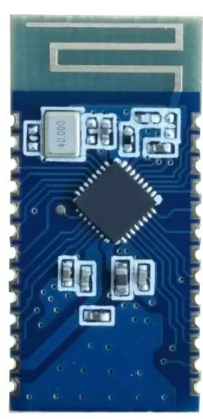
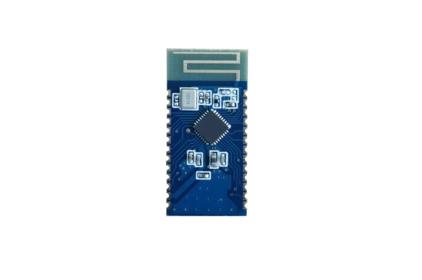
JDY-33 Bluetooth SPP Serial Port Transparent Transmission Module
Version
| Version | Date | Description |
| V1.2 | 2019-05-15 | Release version |
| V1.4 | 2019-06-01 | Added AT+STTS instruction |
| V1.6 | 2019-06-15 | This version has been validated by a large number of customers and been largely produced. It is very stable. It is recommended to use V1.6 version. |
Product Introduction and Application
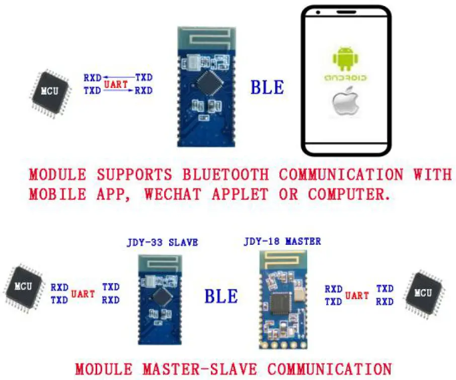
JDY-33 Bluetooth is designed based on Bluetooth 3.0 SPP+BLE, which can support data transmission of Windows, Linux, Android, and IOS, with 2.4 GHZ working frequency band, GFSK modulation mode, 6 db maximum transmission power, 30 meters of maximum transmission distance. It supports users to modify device name, baud rate and other instructions through AT commands, which is convenient, fast and flexible.
JDY-33 has obvious advantages. It supports Bluetooth communication between SPP and computer, APP or Wechat applet, and communication between master and slave of JDY-18.
Product Application
JDY-33 is a classic Bluetooth+BLE dual-mode Bluetooth, which can communicate with
Bluetooth-enabled computers (desktop, notebook), mobile phones (Android), and IOS. It can be applied to
- Bluetooth POS
- Thermal printer
- Smart home control
- Automobile ODB detection equipment
- Application of Bluetooth transparent transmission products
- Shared chargers, weight scal
Detailed Module Parameters
| Model | JDY-33 |
| Working frequency band | 2.4GHZ |
| Communication interface | UART |
| Working voltage | 1.8-3.6V(3.3V recommended) |
| Working temperature | -40℃ – 80℃ |
| Antenna | Built-in PCB antenna |
| Transmission distance | 30 meters |
| Master-slave support | Slave machine |
| Module size | 26.7 * 13 *1.7 mm(Length, width and height) |
| Bluetooth version | Bluetooth 3.0 SPP + BLE4.2 |
| SMT Welding Temperature | <260℃ |
| Working Current | 6.5mA |
| Deep sleep current | <10uA |
| Transmitting power | 6db(Maximum) |
| Receiving sensitivity | -96dbm |
| SPP maximum throughput | 16K bytes/s(android、windows) When connected with Android and computer Bluetooth, the communication speed can reach 16K bytes/s, and there is no loss of packets (supporting serial port to receive and send data |
| continuously). | |
| BLE | 4K bytes/s(android、IOS) The communication speed is 4K bytes/s when BLE connects with IOS or Android (supporting 38400 baud rate to continuously send and receive data. If the baud rate is higher than 38400, the data cannot be sent continuously, and delay shall be added in the middle) |
Pin function and Application
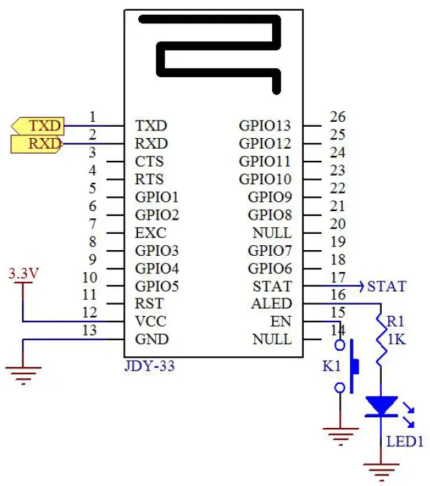
JDY-33 applications only need to connect VCC, GND, RXD and TXD pins. The connection state requires a disconnect, send AT+DISC\r\n. Send AT+SLEEP\r\n for deep SLEEP in unconnected state. Deep sleep can be awakened by the falling edge of EN pin, or by sending data through serial port. It is generally recommended to use serial port to send AT+VERSION\r\n instruction to wake up.
Pin function description
| Pin No. | Pin function | Pin function description |
| 1 | TXD | Serial port output in (TTL Level) |
| 2 | RXD | Serial port input pin (TTL level) |
| 3 | CTS | Serial port flow control CTS pin |
| 4 | RTS | Serial port flow control RTS pin |
| 5 | GPIO1 | Default no function (Input and output of IO control can be customized according to customer needs) |
| 6 | GPIO2 | Default no function (Input and output of IO control can be customized according to customer needs) |
| 7 | EXC | Default no function (Input and output of IO control can be customized according to customer needs) |
| 8 | GPIO3 | Default no function (Input and output of IO control can be customized according to customer needs) |
| 9 | GPIO4 | Default no function (Input and output of IO control can be customized according to customer needs) |
| 10 | GPIO5 | Default no function (Input and output of IO control can be customized according to customer needs) |
| 11 | RST | Reset (Low level effective) |
| 12 | VCC | Power supply (1.8-3.6V) |
| 13 | GND | Ground |
| 14 | NULL | |
| 15 | EN | Input pin for sleep awakening (falling edge valid) |
| 16 | ALED | Broadcast status pin (Flash when not connected, output high level after connected) |
| 17 | STAT | Connection status pin (Low level when not connected, output high level after connected) |
| 18 | GPIO6 | Default no function (Input and output of IO control can be customized according to customer needs) |
| 19 | GPIO7 | Default no function (Input and output of IO control can be customized according to customer needs) |
| 20 | NULL | |
| 21 | GPIO8 | Default no function (Input and output of IO control can be customized according to customer needs) |
| 22 | GPIO9 | Default no function (Input and output of IO control can be customized according to customer needs) |
| 23 | GPIO10 | Default no function (Input and output of IO control can be customized according to customer needs) |
| 24 | GPIO11 | Default no function (Input and output of IO control can be customized according to customer needs) |
| 25 | GPIO12 | Default no function (Input and output of IO control can be |
| customized according to customer needs) | ||
| 26 | GPIO13 | Default no function (Input and output of IO control can be customized according to customer needs) |
PCB Package Size
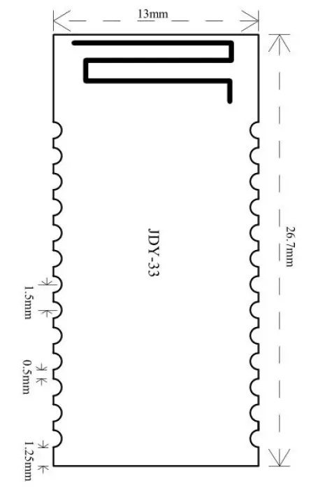
PCB package is fully compatible with JDY-30, JDY-31, JDY-09, JDY-32
Serial Port AT Instruction Set
JDY-33 module serial port must add \r\n when sending AT instruction
| No. | Instruction | Function | Default |
| 1 | AT | Test | |
| 2 | AT+VERSION | Version number | JDY-33-V1.1 |
| 3 | AT+STAT | Query connection status | 00 |
| 4 | AT+SLEEP | Sleep | – |
| 5 | AT+BAUD | Baud rate setting and query | 9600 |
| 6 | AT+NAME | Broadcast name setting and query | JDY-33-SPP |
| 7 | AT+NAMB | BLE broadcast name setting and query | JDY-33-BLE |
| 8 | AT+PIN | Connection password setting and query | 1234 |
| 9 | AT+LADDR | MAC address of module query | |
| 10 | AT+RESET | Soft reset | – |
| 11 | AT+DEFAULT | Restore factory settings | – |
| 12 | AT+DISC | Disconnect (valid in connection state) | – |
| 13 | AT+TYPE | Setting and query paired password switch | 0 |
| 14 | AT+ENLOG | Serial port state output enable | 1 |
| 15 | AT+UUIDLEN | Setting and query UUID length | 0 |
| 16 | AT+SVRUUID | BLE service UUID setting and query | FFE0 |
| 17 | AT+CHRUUID | BLE feature UUID setting and query | FFE1 |
| 18 | AT+CRXUUID | BLE feature UUID setting and | FFE2 |
| query | |||
| 19 | AT+UARTMOD E | Serial port parity bit setting and query | No check bit |
| 20 | AT+STTS | STAT pin function setting and query | 0 |
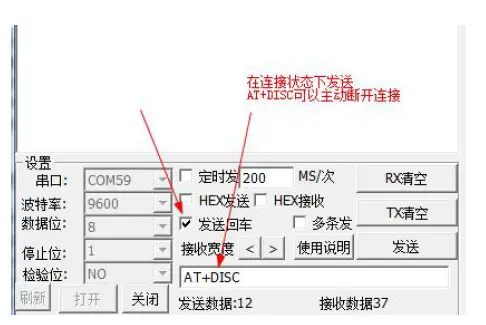
Method of sending disconnection instructions in connection state
- Test instruction
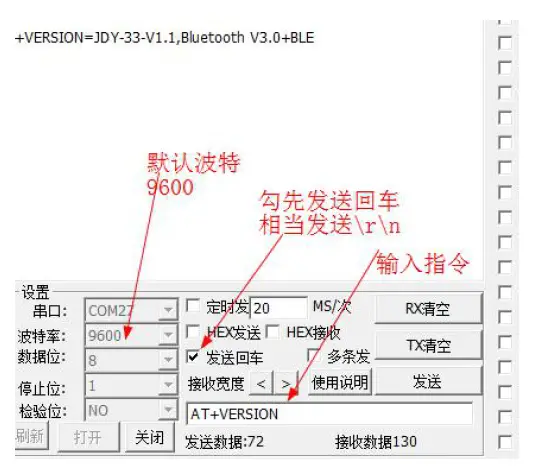
Instruction Response Parameter AT +OK None - Query version number
Instruction Response Parameter AT+VERSION +VERSION=JDY-33-V1.1,Bluetooth V3.0+BLE None - Query connection status
Instruction Response Parameter AT+STAT
+STAT=<Param>
Param(01-02) 01: Indicates BLE connected
02: Indicates SPP
connected
Connection status can be queried by this instruction in connection state.
- Setting deep sleep
Instruction Response Parameter AT+SLEEP +OK None No broadcasting after deep sleep, the current is about 3uA.
- Baud Rate Setting/Query
Instruction Response Parameter AT+BAUD<Param> +OK Param:(4 to 9) 2:2400 3:4800 AT+BAUD +BAUD=<Param> 4:9600 5:19200 6:38400 7:57600 8:115200 9:128000 JDY-33 supports 128000 baud rate continuous data transmission without losing packets, and the transmission speed can reach 16K bytes per second.
- SPP Broadcast Name Setting/Query
Instruction Response Parameter AT+NAME<Param> +OK Param:SPP Broadcast Name Maximum: 18 bytes Default broadcast name:
JDY-33-SPP
AT+NAME +NAME=<Param> - BLE Broadcast Name Setting/Query
Instruction Response Parameter AT+NAMB<Param> +OK Param:BLE Broadcast Name Maximum: 18 bytes Default broadcast name:
JDY-33-BLE
+NAME=<Param> - SPP Bluetooth Paired Password
Instruction Response Parameter AT+PIN<Param> +OK Param:4 bit password Defaulted PIN:1234
AT+PIN +PIN=<Param> - Bluetooth MAC address
Instruction Response Parameter AT+LADDR<Param> +OK Param:MAC address is a hexadecimal string
AT+LADDR +LADDR=<Param> Query MAC address: AT+LADDR\r\n
Setting MAC address: AT+LADDR112233445566\r\n Setting MAC address: AT+LADDR11:22:33:44:55:66\r\n - Reset
Instruction Response Parameter AT+RESET +OK None - Restore factory configuration
Instruction Response Parameter AT+DEFAULT +OK None - Disconnect
Instruction Response Parameter AT+DISC +OK None Effective after connection
- Setting/Query SPP Password Connection
Instruction Response Parameter AT+TYPE<Param> +OK Param(01-02) 1: SPP connection AT+TYPE +TYPE=<Param> with password 0: SPP connection with no password Default: 0 - Serial port state output enable setting/query
Instruction Response Parameter AT+ENLOG<Param> +OK Param:1 or 0 AT+ENLOG +ENLOG=<Param> 1: Open serial port status output 0: Close serial port status output Default: 1 - UUID Length Setting/Query
Instruction Response Parameter AT+UUIDLEN<Param> +OK Param:1 or 0 AT+UUIDLEN +UUIDLEN=<Param> 1:UUID length 128 0:UUID length 16 Default: 0 - BLE Service UUID Setting/Query
Instruction Response Parameter AT+SVRUUID<Param> +OK Param:UUID string Default: FFE0
AT+SVRUUID +SVRUUID=<Param> - BLE feature UUID Setting/Query
Instruction Response Parameter AT+CHRUUID<Param> +OK Param:UUID string Default: FFE1
AT+CHRUUID +CHUUUID=<Param> - BLE feature UUID Setting/Query
Instruction Response Parameter AT+CRXUUID<Param> +OK Param:UUID string Default: FFE2
AT+CRXUUID +CRXUUID=<Param> - Serial port parity bit setting and query
Instruction Response Parameter Param1:Fixed to 0 AT+UARTMODE<Param1>,<P +OK Param2:0 to 2 aram2> 0:No check bit 1:Odd 2:Even AT+UARTMODE +UARTMODE=<Param1>,<Pa Default: 0 ram2> - STAT pin function setting and query
| Instruction | Response | Parameter |
|
AT+STTS<Param> |
+OK | Param:0 to 1
0: STAT pins are low level when not connected, high level after connection, low level after disconnection |
|
AT+STTS |
+STTS=<Param> | |
| 1: STAT pins are low level when not connected, high level after connection, and output low level after receiving data. If no data is received, high level is output after delay of 1.5s, and low level is output after disconnect | ||
| Default: 0 |
Master-slave communication between JDY-18 and JDY-33
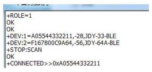
- JDY-18 is configured as a master: AT+ROLE1
- JDY-18 search slave: AT+INQ
- JDY-18 connection search gets slave machine: AT+CONNA05544332211
- Output slave MAC address after successful connection: +CONNECTED>>0xA05544332211
FCC statement
This device complies with Part 15 of the FCC rules. Operation is subject to the following two conditions: 1) this device may not cause harmful interference, and 2) this device must accept any interference received, including interference that may cause undesired operation.
Note: This equipment has been tested and found to comply with the limits for a Class B digital device, pursuant to part 15 of the FCC Rules. These limits are designed to provide reasonable protection against harmful interference in a residential installation. This equipment generates uses and can radiate radio frequency energy and, if not installed and used in accordance with the instructions, may cause harmful interference to radio communications. However, there is no guarantee that interference will not occur in particular installation. If this equipment does cause harmful interference to radio or television reception, which can be determined by turning the equipment off and on, the user is encouraged to try to correct the interference by one or more of the following measures:
- Reorient or relocate the receiving antenna.
- Increase the separation between the equipment and receiver.
- Connect the equipment into an outlet on a circuit different from that to which the receiver is connected.
- Consult the dealer or an experienced radio/TV technician for help.
Changes or modifications not expressly approved by the party responsible for compliance could void the user’s authority to operate the equipment.
FCC Radiation Exposure Statement
This device complies with FCC RF radiation exposure limits set forth for an uncontrolled environment. This transmitter must not be co-located or operating in conjunction with any other antenna or transmitter.
Integration instructions for host product manufacturers according to KDB 996369 D03 OEM Manual v01
List of applicable FCC rules
FCC Part 15.247.
Specific operational use conditions
This device is intended only for OEM integrators under the following conditions:
- The transmitter module may not be co-located with any other transmitter or antenna.
As long as the condition above is met. further transmitter test will not be required. However, the OEM integrator is still responsible for testing their end-product for any additional compliance requirements required with this module installed.
IMPORTANT NOTE: In the event that these conditions can not be met (for example certain laptop configurations or co-location with another transmitter), then the FCC authorization is no longer considered valid and the FCC ID can not be used on the final product. In these circumstances, the OEM integrator will be responsible for re-evaluating the end product (including the transmitter) and obtaining a separate FCC authorization. The OEM integrator has to be aware not to provide information to the end user regarding how to install or remove this RF module in the user’s manual of the end product which integrates this module. The end user manual shall include all required regulatory information/warning as show in this manual.
Limited module procedures
Additional testing and certification is necessary when specific host originally granted with this module.
Trace antenna designs
The module may be operated only with the PCB antenna with which it is authorized.
RF exposure considerations
Colocated issue shall be met as mentioned in “Specific operational use conditions”.
Product manufacturer shall provide below text in the end-product manual
“Radiation Exposure Statement:
The product comply with the US portable RF exposure limit set forth for an uncontrolled environment and are safe for intended operation as described in this manual. The further RF exposure reduction can be achieved if the product can be kept as far as possible from the user body or set the device to lower output power if such function is available.”
Antennas
| Model name | Antenna type | Antenna gain |
| JDY33 | PCB | -2dBi |
Label and compliance information
Product manufacturers need to provide a physical or e-label stating “Contains FCC ID: 2AXM8-JDY-33” with finished product
Information on test modes and additional testing requirements
Test tool: RF Test_V1.8.exe shall be used to set the module to transmit continuously
Additional testing, Part 15 Subpart B disclaimer
The module is only FCC authorized for the specific rule parts listed on the grant, and that the host product manufacturer is responsible for compliance to any other FCC rules that apply to the host not covered by the modular transmitter grant of certification. The final host product still requires Part 15 Subpart B compliance testing with the modular transmitter installed.
 Module Jdy-32 Bluetooth User Manual")


 Module User Manual")


