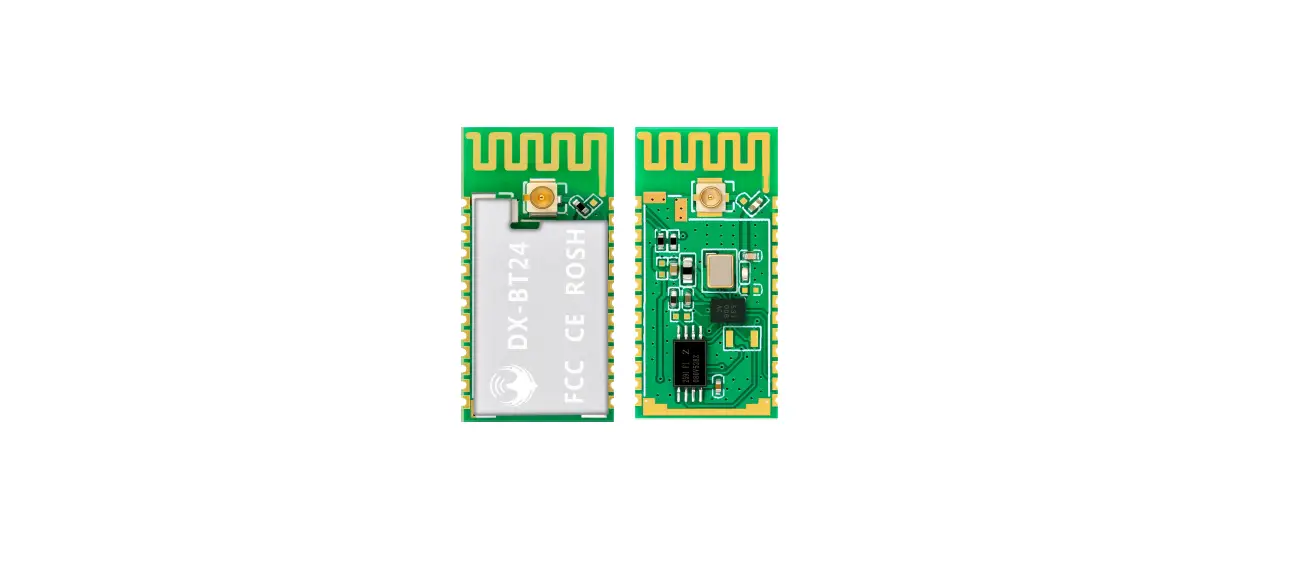
Shen Zhen Dx Smart Technology DX-BT24 Bluetooth Module
Overview
DX- BT24 5.1 Bluetooth module is built by Shenzhen DX- SMART Technology Co., Ltd. for intelligent wireless data transmission. It uses the British DAILOG 14531 chip, configures 256Kb space, and follows V5.1 BLE Bluetooth specifications. Support AT command, users can change the serial port baud rate, device name, pairing password and other parameters as needed, flexible use. This module supports UART interface and supports Bluetooth serial port transparent transmission. It has the advantages of low cost, small size, low power consumption, high sensitivity of sending and receiving, etc. It can realize its powerful functions with only a few peripheral components simple operation, high cost performance and technology leading edge.
Module default parameters
| Bluetooth Protocol | Bluetooth Specification V5.1 BLE |
| Working Frequency | 2.4GHz ISM band |
| Communication Interface | UART |
| Power Supply | 3.3V |
| Communication distance | 80M (Open and unobstructed environment) |
| Physical Dimension | 27(L)mm x 13 (W)mm x 2(H) mm |
| Bluetooth Authentication | FCC CE ROHS REACH |
| Bluetooth Name | BT24 |
| Serial Port Parameters | 9600、8 data bits、1 stop bit、No check、No flow control |
| Service UUID | FFE0 |
| Notify\Write UUID | FFE1 |
| Write UUID | FFE2 |
| Work temperature | MIN:-40℃ – MAX:+85℃ |
| Customized requirements | If you have other special function requirements, you can contact us to customize the module. |
Application area
DX-BT24 module supports BT5.1 BLE protocol, which can be directly connected to iOS devices that have BLE Bluetooth function, and supports background program resident operation. Successful application of BT24 module:
- Bluetooth wireless data transmission;
- Mobile phones, computer peripherals;
- Handheld POS device;
- Medical equipment wireless data transmission;
- Smart Home Control;
- Automotive Inspection OBD Equipment;
- Bluetooth printer;
- Bluetooth remote control toy;
- The anti-lost device, LED light control;
Power consumption parameters
| Broadcast interval: 540ms | |||
| Mode | Status | Current | Unit |
| Low power mode | Discoverable | 19 | uA |
| Connected | 341 | uA | |
| Normal working mode | Discoverable | 270 | uA |
| Connected | 341 | uA | |
| When transparently transmitting data(11520Bytes/s) | Connected | MIN:341uA MAX:3.5 (MIN is the minimum amount of data, MAX is the power consumption at the maximum amount of data) | mA |
Radio frequency characteristics
| Rating | Value | Unit |
| BLE Transmit power | -19.5~+2.5 | dBm |
| BLE Sensitivity | -94 | dBm |
Transparent transmission parameters
Data throughput
| Android ->BT24 -> UART | UART ->BT24 -> Android | ||
| Baud rate | 115200 | Baud rate | 115200 |
| Connection interval (ms) | 15 | Connection interval (ms) | 15 |
| Serial packet size (bytes) | 230 | Serial packet size (bytes) | 320 |
| Transmission interval (ms) | 20 | Transmission interval (ms) | 20 |
| Throughput (bytes/s) | 10120 | Throughput (bytes/s) | 10626 |
| Characteristic Write | Write without Response | Characteristic Notify | Notify |
| iPhone 6 ->BT24 -> UART | UART ->BT24 -> iPhone 6 | ||
| Baud rate | 115200 | Baud rate | 115200 |
| Connection interval (ms) | 30 | Connection interval (ms) | 30 |
| Serial packet size (bytes) | 140 | Serial packet size (bytes) | 180 |
| Transmission interval (ms) | 20 | Transmission interval (ms) | 50 |
| Throughput (bytes/s) | 5600 | Throughput (bytes/s) | 3240 |
| Characteristic Write | Write without Response | Characteristic Notify | Notify |
Note: This table parameter is for reference only and does not represent the maximum data throughput that the module can support.
Module pin description and minimum circuit diagram
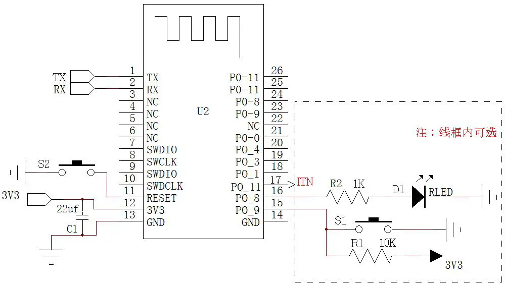
Pin function description
| Pin number | Pin name | Pin description |
| 1 | P0_6 | Serial data output |
| 2 | P0_7 | Serial data input |
| 3 | NC | NC |
| 4 | NC | NC |
| 5 | NC | NC |
| 6 | NC | NC |
| 7 | SWDIO | Debug data port |
| 8 | SWCLK | Debug clock port |
| 9 | SWDIO | Connected to pin 7, IO port can be customized |
| 10 | SWCLK | Connected to pin 8, IO port can be customized |
| 11 | Reset | Reset(Input 200ms low level pulse) |
| 12 | VCC | V3.3 |
| 13 | GND | Land |
| 14 | GND | Land |
|
15 |
P0_9 | Disconnect pin(200ms low power pulse disconnection) Low power mode wake up(200ms low power pulse wake up) |
| 16 | P0_8 | LED light pin(Not connected: 1s on, 1s off, connected: 3s on, 50ms off) |
| 17 | P0_11 | Bluetooth connection indicator (not connected low, connection high) |
| 18 | P0_1 | NC(Can only be left floating) |
| 19 | P0_3 | NC(Can only be left floating) |
| 20 | P0_4 | NC(Can only be left floating) |
| 21 | P0_0 | Programmable input and output |
| 22 | NC | NC |
| 23 | P0_9 | Connected to pin 15, IO port can be customized |
| 24 | P0_8 | Connected to pin 16, IO port can be customized |
| 25 | P0_11 | Connected to pin 17, IO port can be customized |
| 26 | P0_11 | Connected to pin 17, IO port can be customized |
Detailed description of function pins
16 feet (P0_8): LED indicator pin
Used to indicate the status of the Bluetooth module, the LED flashing mode corresponds to the status of the Bluetooth module, see the table below:
| Module | LED display | Module status |
| Slave module | Flashes slowly and evenly(1s-on,1s-off) | standby mode |
| Bright 3s Extinguish 50ms(3s-on,50ms-off) | Connection Status | |
| Light off in low power mode | ||
Pin 17 (P1_11): connection status indication pin
| Pin status | Module status |
| Output low | standby mode |
| Output high level | Connection Status |
Pin 15 (P0_9): connection interruption pin (the module is in the connected state is valid)
| Pin status | Module status |
| No action | Connection Status |
| Input 200ms low-level pulse from the module | The connection is interrupted and the module enters low power consumption mode(Enter the previously set working mode, if not set, it is the normal working mode) |
Pin15 (P0_9): low-power mode wake-up pin (the module is effective in low-power mode)
| Pin status | Module status |
| No action | Low power mode |
| Input 200ms low-level pulse from the module | Wake up from low power mode, the module enters the standby state |
Comparison of low power mode and normal working mode
| Normal working mode | Low power mode | |
| AT command | Send AT commands after power-on | P0_9:200ms low power pulse wake up to send AT command |
| Light status | Even slow blinking | light is not on |
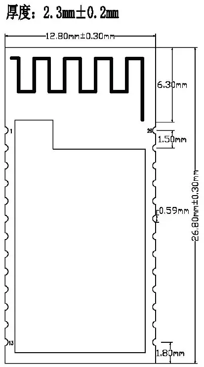
Dimensions
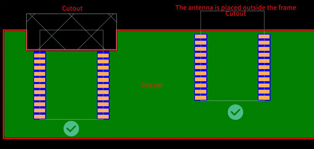
LAYOUT Precautions:
The DX-BT24 Bluetooth module works in the 2.4G wireless band. It should try to avoid the influence of various factors on the wireless transceiver. Pay attention to the following points:
- the product shell surrounding the Bluetooth module to avoid the use of metal, when using part of the metal shell, should try to make the module antenna part away from the metal part.
- The internal metal connecting wires or metal screws of the product should be far away from the antenna part of the module.
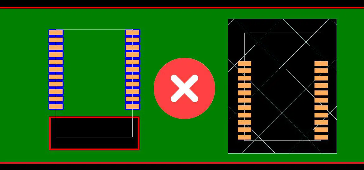
- The antenna part of the module should be placed around the PCB of the carrier board. It is not allowed to be placed in the board, and the carrier board under the antenna is slotted. The direction parallel to the antenna is not allowed to be copper or traced. It is also a good choice to directly expose the antenna part out of the carrier board.
- It is recommended to use insulating material for isolation at the module mounting position on the substrate. For example, put a block of screen printing (TopOverLay) at this position.
Recommend
Not recommend
AT COMMAND
(Note: AT command mode when the module is not connected)
- AT command, which belongs to the character line instruction, is parsed according to the line (that is, AT command must be returned by carriage return or \r\n, a hexadecimal number is 0D0A)
- The AT command supports case and the instruction prefix is AT+, which can be divided into parameter setting instructions and read instructions.
- Set the instruction format: AT+<CMD><PARAM> Operation returns successfully:+<CMD>=<PARAM>\r\n OK\r\n Failure does not return characters.In addition to the 9th and 10th settings, the other parameters need to be restarted after setting the parameters for the new parameters to take effect.
- Read instruction format: AT+<CMD>Operation succeeds: +<CMD>=<PARAM>\r\n Failure does not return a return character.
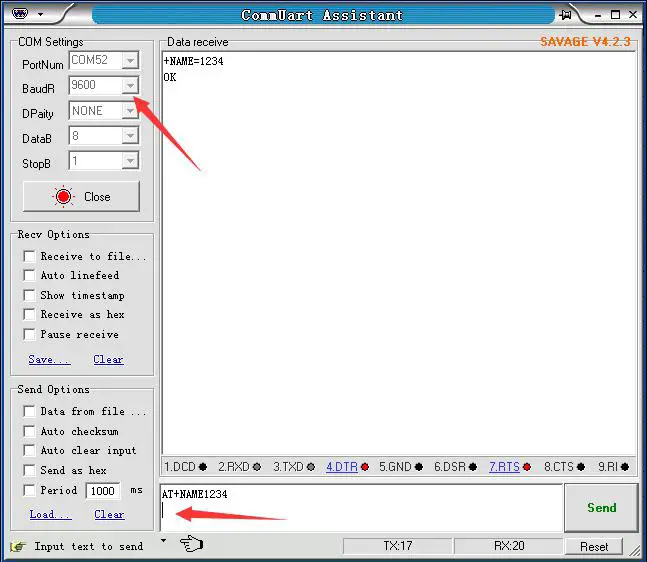
AT command format example (Figure 1 is AT test command, Figure 2 is to change the Bluetooth name to 1234):
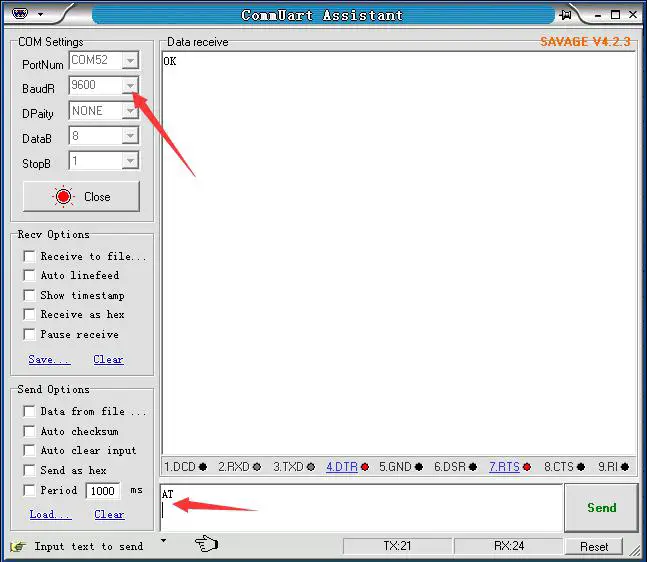
Test Command:
| Function | Command | Response | Description |
| Test instructions | AT \r\n | OK\r\n |
Get The Software Version:
| Function | Command | Response | Description |
| Query version number | AT+VERSION\r\n | +VERSION=<version>\r\n
OK\r\n | <version > Software
version number |
Note:The version will be different depending on different modules and customization requirements.
Query Module Bluetooth MAC:
| Function | Command | Response | Description |
| Query module MAC
address | AT+LADDR\r\n | +LADDR=<laddr>\r\n | <laddr> Bluetooth 12-bit
MAC Address Code |
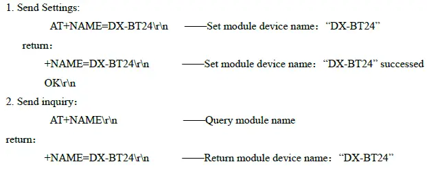
Set/Query Device Name:
| Function | Command | Response | Description |
| Query module Bluetooth
name | AT+NAME\r\n | +NAME=<name>\r\n | <name> Bluetooth name, up to 20 bytes Default name: BT24 |
| Set the module
Bluetooth name | AT+NAME<name
>\r\n | +NAME=<name>\r\n
OK |
Example:
Settings\Query—Bluetooth name suffix MAC:
| Function | Command | Response | Description |
| Query Bluetooth
name suffix MAC | AT+NAMAC\r\n | +NAMAC=<Param>\r\n | <Param >(0,1,2) 0: No MAC suffix after the name 1:Open name suffix 12-digit MAC。2:Open name suffix 6-digit MAC。 Default:0 |
| Set Bluetooth name suffix MAC | AT+NAMAC<Param>\r\n | +NAMAC=<Param>\r\n OK |
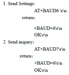
Set/Query – Serial Port Baud Rate:
| Function | Command | Response | Description |
| Query module baud | AT+BAUD\r\n | +BAUD=<baud>\r\n | <baud> Baud rate |
| Set the module baud | AT+BAUD<bau | +BAUD=<baud>\r\n | corresponding serial |
| number | |||
| d>\r\n | OK\r\n | 1:2400 | |
| 2:4800 | |||
| 3:9600 | |||
| 4:19200 | |||
| 5:38400 | |||
| 6:57600 | |||
| 7:115200 | |||
| Default:3(9600) |
Note: The module must be re-powered after setting the baud rate, enabling the new baud rate for data communication and AT command resolution.
Example:
Setting the Serial Port Baud Rate: 57600
Set/Query – Serial Port Stop Bit:
| Function | Command | Response | Description |
| Query module serial port | AT+STOP\r\n | +STOP=<Param>\r\n | < Param> Stop bit |
| stop bit | 0 -1 Stop bit | ||
| Set module serial port | AT+STOP<Param | +STOP=<Param>\r\n | 1 -2 Stop bit |
| stop bit | >\r\n | OK | Default:0 |
Set / Query – Serial Parity Bit:
| Function | Command | Response | Description |
| Query module serial
parity bit | AT+PARI\r\n | +PARI=<Param>\r\n | < Param> Check Digit 0 -1 No check 1 -2 Odd parity
2 -2 Even parity |
| Set the module serial
parity bit | AT+PARI<Param >\r\
n | +PARI=<Param>\r\n
OK |
Set/Query—Notify the host computer connection status : The connection success module returns OK+CONN:
| Function | Command | Response | Description |
| Query status | AT+NOTI\r\n | +NOTI=<Param>\r\n | < Param> Check Digit 0- Not notified 1- Notice Defaults:0 |
| Set status | AT+NOTI<Para
m>\r\n | +NOTI=<Param>\r\n
OK |
Set/Query—Notification connection with address code: The connection success module returns OK+CONN0x112233445566:
| Function | Command | Response | Description |
| Notification connection
with address code | AT+NOTP\r\n | +NOTP=<Param>\r\n | < Param> Check Digit 0- Not notified 1- Notice
Defaults:0 |
| Notification connection
with address code | AT+NOTP<Para
m>\r\n | +NOTP=<Param>\r\n
OK |
Settings\Query—SERVICE UUID:
| Function | Command | Response | Description |
| Query service UUID | AT+UUID\r\n | +UUID =<service>\r\n | <service> UUID |
| Set service UUID | AT+UUID<service | +UUID =<service>\r\n | Default service |
| >\r\n | OK | UUID:FFE0 | |
| (This UUID is a 4-digit | |||
| hexadecimal number) |
Example:
Set the service UUID to FE00
- Send Settings:
- AT+UUID0XFF00 \r\n return: +UUID=0XFF00 r\n OK
settings\Query—NOTIFY UUID\ WRITE UUID:
| Query module
notify\write UUID | AT+CHAR\r\n | +CHAR=<UUID >\r\n | <UUID>notify\write UUID Default:FFE1 (This UUID is a 4-digit hexadecimal number) |
| Set module notify \write UUID | AT+CHAR<UUID>
\r\n | +CHAR =<UUID>\r\n OK |
Note: This channel is a readable and writable channel (ie it can be read or written) Example: Set the notify \write UUID to:FE01
- Send settings:
- AT+CHAR0XFE01\r\n return: +CHAR= FE01r\n OK\r\n
Settings\Query—WRITE UUID:
| Function | Command | Response | Description |
| Query module write
UUID | AT+WRITE\r\n | +WRITE=<UUID >\r\n | <UUID> write UUID Default:FFE2 (This UUID is a 4-digit
hexadecimal number) |
| Set module write UUID | AT+WRITE<UUID
>\r\n | +WRITE=<UUID>\r\n
OK |
Settings\Query – Low Power Mode:
| Function | Command | Response | Description |
| Query module low
power mode | AT+PWRM\r\n | +PWRM=<Param>\r\n | < Param >(0 、 1) 0:Low power mode 1:working mode Default:1 |
| Set module low power
mode | AT+PWRM<Para
m>\r\n | +PWRM=<Param>\r\n
OK |
Settings\Query – Broadcast time interval:
| Function | Command | Response | Description |
| Query Broadcast time
interval | AT+ ADVI \r\n | + ADVI=<Param>\r\n | Param:0~F 0—100ms 1—152.5ms |
| Set Broadcast time interval | AT+ADVI<Param>\r\n | + ADVI=<Param>\r\n OK | 2—211.25ms 3—318.75ms 4—417.5ms 5—546.25ms 6—760ms 7—852.5ms 8—1022.5ms 9—1285ms A—2000ms B—3000ms C—4000ms D—5000ms E—6000ms F—7000ms Default:5 |
Note: This instruction can be used to reduce power consumption
Settings\Query – Module transmit power:
| Function | Command | Response | Description |
| Query module transmit | AT+POWE\r\n | +POWE=<POWE>\r\n | <POWE>: 1:-19.5 dB 2:-13.5 dB 3:-10dB 4:-7dB 5:-5dB 6:-3.5dB 7:-2dB 8:-1dB 9:0dB A:+1dB B:+1.5dB C:+2.5dB
Default:C |
| power | |||
| Set module transmit power | AT+POWE<POWE> | +POWE=<POWE>\r\n | |
| \r\n | OK\r\n |
Settings\Query—APP AT command:
| Function | Command | Response | Description |
| Query APP AT commands | AT+APPAT\r\n | +APPAT=<Param>\r\n | <Param >(0,1,2) 0:Close APP AT command |
| Set APP AT command | AT+APPAT<Param>\r\n | +APPAT=<Param>\r\n |
| OK | 1:Open APP AT command Default:0 |
Note: This command opens the user to send AT commands with APP (Note: APPAT command can only be enabled through UART; if you need to enter transparent transmission mode, you need to set to disable APP AT command.)
Settings\Query—Bluetooth device type:
| Function | Command | Response | Description |
| Query Bluetooth
device type | AT+TYPE\r\n | +TYPE=<Param>\r\n | <Param >: 0x0000:No types pecified 0x0040:Phone type 0x0080:Laptop type 0x03c1:Keyboard type 0x03c2:Mouse type … Default:0x0000 |
| Set Bluetooth device type | AT+TYPE<Param>\ r\n | +TYPE=<Param>\r\n OK |
Software restart:
| Function | Command | Response | Description |
| Software restart | AT+RESET\r\n | OK\r\n |
Restore default settings:
| Function | Command | Response | Description |
| Restore default settings | AT+DEFAULT \r\n | OK\r\n |
Contact us
Shen Zhen DX-SMART Technology Co., Ltd. Address:511,Building C, Yuxing Technology Park, Yuxing Chuanggu, Bao’an District, Shenzhen, China Tel: 0755-2997 8125 Fax: 0755-2997 8369
Website: http://www.szdx-smart.com/
FCC Statement
FCC standards: FCC CFR Title 47 Part 15 Subpart C Section 15.247 Integral antenna with antenna gain 2.5dBi This device complies with part 15 of the FCC Rules. Operation is subject to the following two conditions: (1) This device may not cause harmful interference, and (2) this device must accept any interference received, including interference that may cause undesired operation. Any Changes or modifications not expressly approved by the party responsible for compliance could void the user’s authority to operate the equipment. Note: This equipment has been tested and found to comply with the limits for a Class B digital device, pursuant to part 15 of the FCC Rules. These limits are designed to provide reasonable protection against harmful interference in a residential installation. This equipment generates, uses and can radiate radio frequency energy and, if not installed and used in accordance with the instructions, may cause harmful interference to radio communications. However, there is no guarantee that interference will not occur in a particular installation. If this equipment does cause harmful interference to radio or television reception, which can be determined by turning the equipment off and on, the user is encouraged to try to correct the interference by one or more of the following measures:
- Reorient or relocate the receiving antenna.
- Increase the separation between the equipment and receiver.
- Connect the equipment into an outlet on a circuit different from that to which the receiver is connected.—Consult the dealer or an experienced radio/TV technician for help.
FCC Radiation Exposure Statement
This modular complies with FCC RF radiation exposure limits set forth for an uncontrolled environment. If the FCC identification number is not visible when the module is installed inside another device, then the outside of the device into which the module is installed must also display a label referring to the enclosed module. This exterior label can use wording such as the following: “Contains Transmitter Module FCC ID: 2AKS8DX-BT24 Or Contains
FCC ID: 2AKS8DX-BT24”
When the module is installed inside another device, the user manual of the host must contain below warning statements;
- This device complies with Part 15 of the FCC Rules. Operation is subject to the following two conditions:
- This device may not cause harmful interference.
- This device must accept any interference received, including interference that may cause undesired operation.
Note: This equipment has been tested and found to comply with the limits for a Class B digital device, pursuant to part 15 of the FCC Rules. These limits are designed to provide reasonable protection against harmful interference in a residential installation. This equipment generates, uses and can radiate radio frequency energy and, if not installed and used in accordance with the instructions, may cause harmful interference to radio communications.
However, there is no guarantee that interference will not occur in a particular installation. If this equipment does cause harmful interference to radio or television reception, which can be determined by turning the equipment off and on, the user is encouraged to try to correct the interference by one or more of the following measures:
- Reorient or relocate the receiving antenna.
- Increase the separation between the equipment and receiver.
- Connect the equipment into an outlet on a circuit different from that to which the receiver is connected.—Consult the dealer or an experienced radio/TV technician for help.
Changes or modifications not expressly approved by the party responsible for compliance could void the user’s authority to operate the equipment. The devices must be installed and used in strict accordance with the manufacturer’s instructions as described in the user documentation that comes with the product. Any company of the host device which installs this modular with single modular approval should perform the test of radiated & conducted emission and spurious emission, etc. according to FCC part 15C: 15.247 and 15.209 & 15.207,15B Class B requirement, Only if the test result complies with FCC part 15C: 15.247 and 15.209 & 15.207,15B Class B requirement, then the host can be sold legally.


