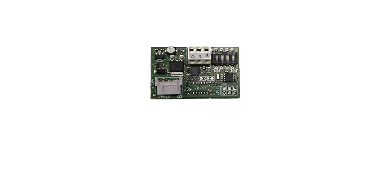
BFt P111468 Board
These boards are compatible only with control panels using the U-link protocol.
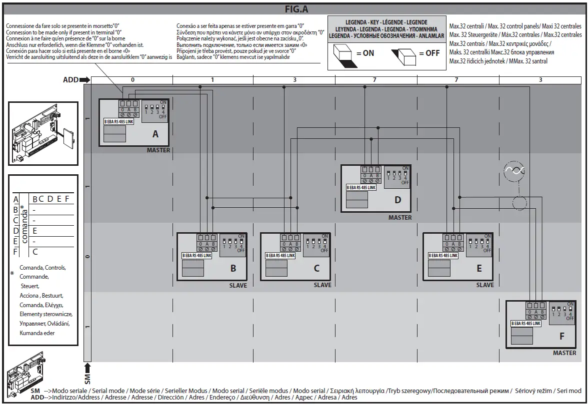
1) Fig.A. Serial connection of Control panels via B EBA RS 485 LINK board This connection involves connecting a number of control panels and can be used for the centralized operation of a number of automated devices. That way, all the automated devices connected to the same Address can be opened or closed with a single command received from the Master control panel. The Address number allows you to create groups of automated devices, each of which answers to its own Master. Each Address can have only one Master. The Master of Address 0 also controls the Masters and Slaves of the other Addresses. Caution: the first control panel in the network must be a Master. The maximum number of control panels that can be connected in a single network is 32. See example in Fig.A.
WIRING REQUIRED FOR OPERATION:
The control panels are connected to each other with 3 wires relating to the B EBA RS 485 LINK interface boards.Use twisted pair cabling only. When using a telephone cable with more than one pair, it is essential to use wires from the same pair (A-B). The length of the cable between one module and the next must not be greater than 250 m.
| SETTINGS REQUIRED FOR OPERATION: | ||
| Logic on control panels | Dip switch settings on B EBA RS 485 LINK | |
| First control panel in network: Master |
Serial mode =1. Address = “assigned address number”. | DIP1=ON DIP2=ON DIP3=ON DIP4=ON |
| Master control panels within network | DIP1=OFF DIP2=OFF DIP3=OFF DIP4=OFF | |
| Slave control panels | Serial mode=0. Address = “assigned address number”. | DIP1=OFF DIP2=OFF DIP3=OFF DIP4=OFF |
| Control panel furthest away | Serial mode =0 (if slave) and 1 (if Master). Address = “assigned address number”. | DIP1=OFF DIP2=OFF DIP3=ON DIP4=ON |
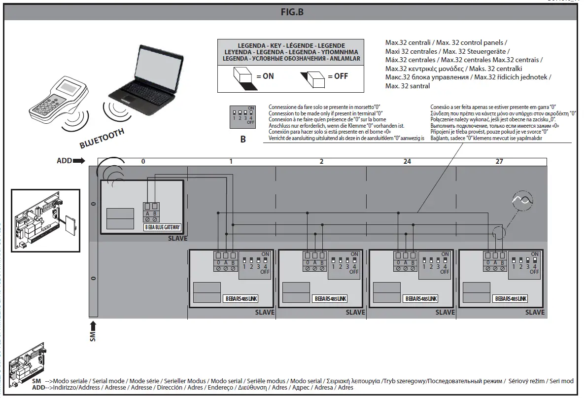
Fig.B/C. U-Link serial connection
The B EBA BLUE GATEWAY and B EBA RS 485 GATEWAY modules allow you to connect a supervisor* to the local network of compatible BFT U-link devices by means of wireless Bluetooth technology for UNI-BLUE and by means of RS-485 twisted pair cabling for UNI-SER. B EBA BLUE GATEWAY and B EBA RS 485 GATEWAY must be connected to the only local network device with the address 0. Each network device must have a different address.
Using a U-link supervisor*, you can address each device in the local U-link network and manage parameters, settings, transmitters and diagnostics.
For information on the features of the supervisor and available functions, refer to the relevant manual.
The network is made up of a device with a B EBA BLUE GATEWAY / B EBA RS 485 GATEWAY module to which all the other devices are connected using twisted pair cabling in a U-link serial connection. The smallest possible network is made up of a single device with the address 0 with a B EBA BLUE GATEWAY / B EBA RS 485 GATEWAY module.
WIRING REQUIRED FOR OPERATION:
The control panels are connected to each other with 3 wires relating to the B EBA RS 485 LINK interface boards. Use twisted pair cabling only. When using a telephone cable with more than one pair, it is essential to use wires from the same pair (A-B). The length of the cable between one module and the next must not be greater than 250 m.
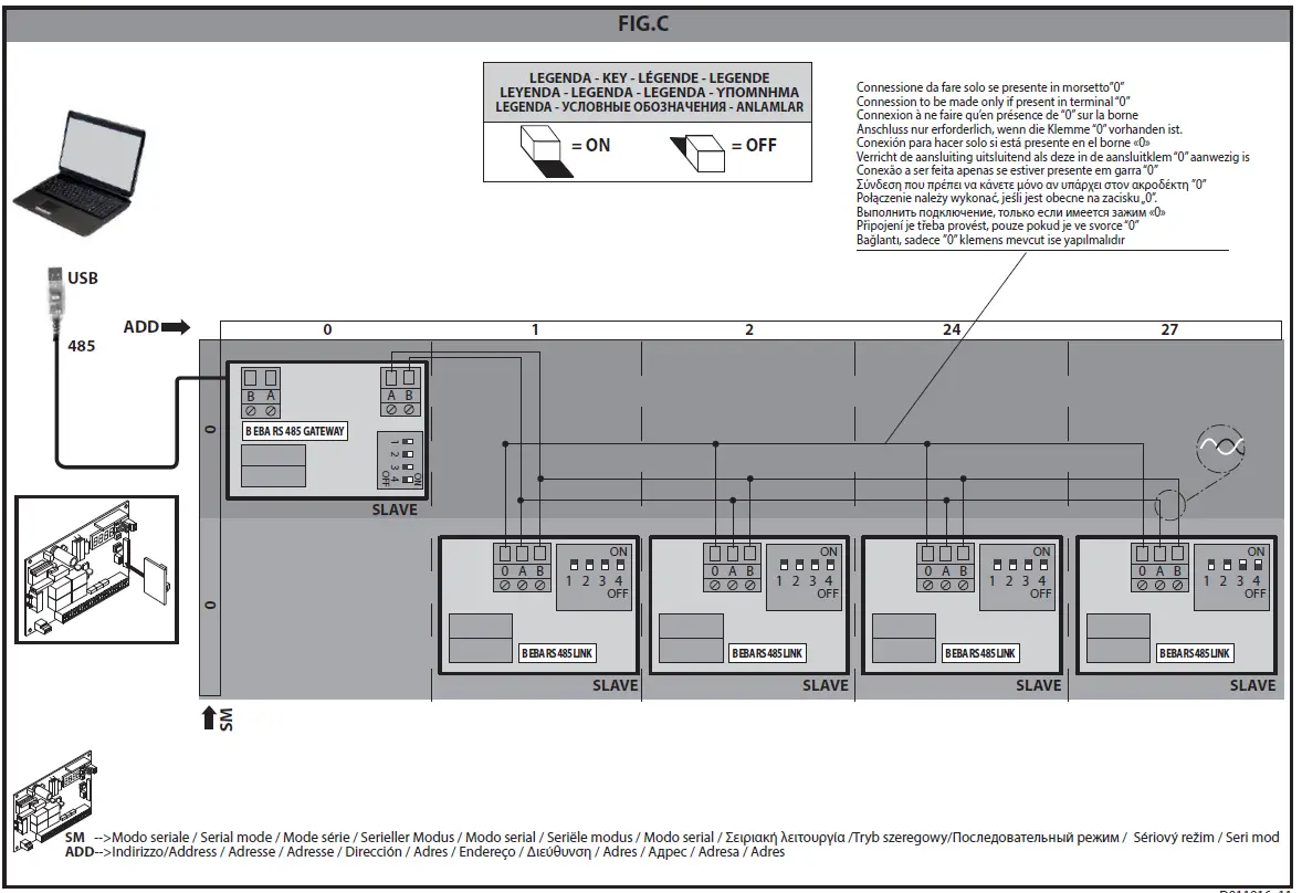
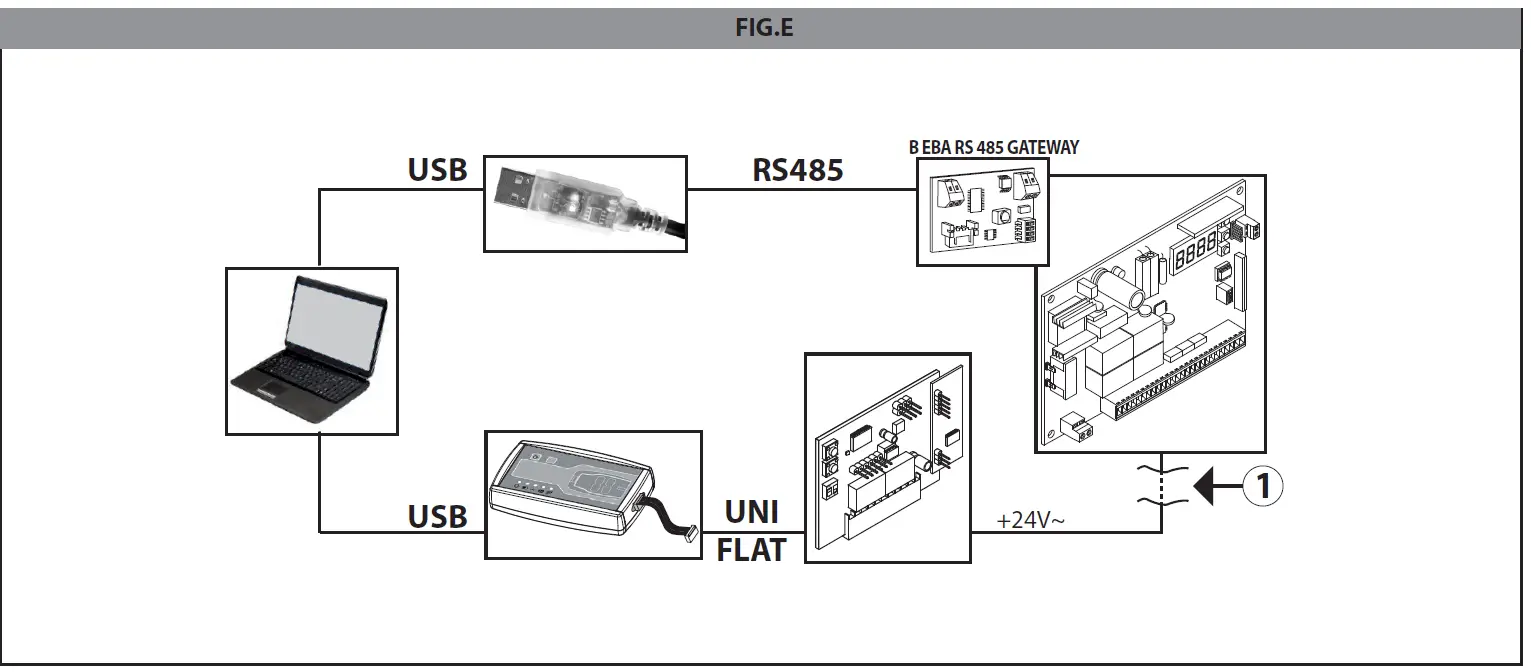
Warning: if a control panel is simultaneously connected to:
- a B EBA RS 485 GATEWAY board and
- an external receiver and simultaneous communications are required:
- from the PC to the B EBA RS 485 GATEWAY board via 485 adapter
- from the same PC to the external receiver board using U-Prog, disconnect the external receiver from the 24V control pa-nel power supply (Fig. E).
| SETTINGS REQUIRED FOR OPERATION: | ||
| Logic on control panels | Dip switch settings | |
| First control panel in | ||
| network with B EBA BLUE | ||
| GATEWAY | Serial mode = 0. Address = 0. | |
| First control panel in network with B EBA RS 485 GATEWAY module | DIP1=ON DIP2=ON DIP3=ON DIP4=ON | |
| Control panels with mo- | Serial mode =0. Address = from 1 to 127 (each control panel must have a different address from the others). | DIP1=OFF DIP2=OFF |
| dule B EBA RS 485 LINK | DIP3=OFF DIP4=OFF | |
| Control panel furthest away with B EBA RS 485 LINK | DIP1=OFF DIP2=OFF DIP3=ON DIP4=ON |
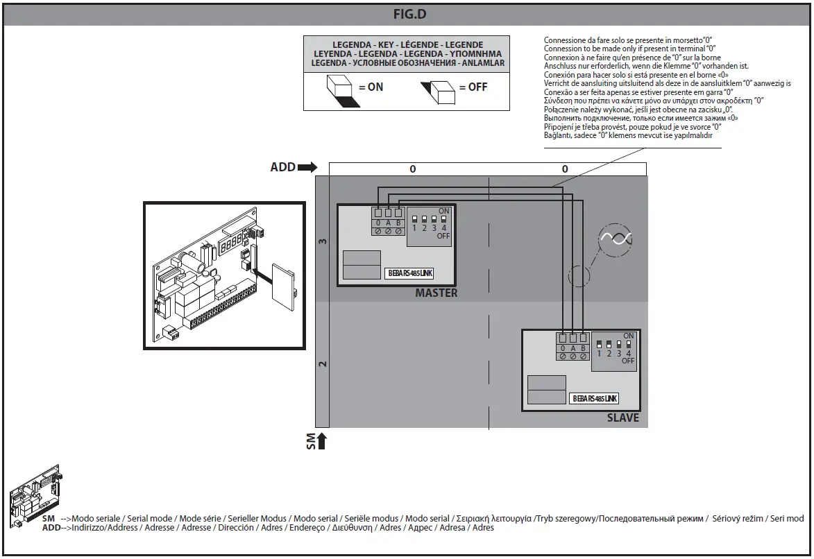
3) Fig.D. Serial connection for Opposite leaves.
This connection involves connecting two control panels for the centralized control of two opposite barriers/gates.
In this case, the Master control panel will simultaneously control the closing and opening of the Slave control panel.
WIRING REQUIRED FOR OPERATION:
- The Master control panel and Slave control panel are connected to each other with 3 wires relating to the B EBA RS 485 LINK interface boards. Use twisted pair cabling only. When using a telephone cable with more than one pair, it is essential to use wires from the same pair (A-B). The length of the cable between one module and the next must not be greater than 250 m. All activation commands, as well as remote commands, must refer to the Master board;
- All photocells (tested or otherwise) must be connected to the Master;
- The safety edges (tested or otherwise) of the Master leaf must be connected to the Master control panel;
- The safety edges (tested or otherwise) of the Slave leaf must be connected to the Slave control panel.
SETTINGS REQUIRED FOR OPERATION:
- On the Master control panel, logic must be set as follows: Serial mode = 3 and Address = 0
- On the B EBA RS 485 LINK board connected to the Master control panel, all Dip switches must be set to ON
- On the Slave control panel, logic must be set as follows: Serial mode = 2 and Address = 0
- On the B EBA RS 485 LINK board connected to the Slave control panel, Dip switches 1 and 2 must be set to OFF and Dip switches 3 and 4 set to ON
| SETTINGS REQUIRED FOR OPERATION: | ||
| Logic on control panels | Dip switch settings on B EBA RS 485 LINK | |
| Master control panel | Serial mode=3. Address = 0 | DIP1=ON DIP2=ON DIP3=ON DIP4=ON |
| Slave control panel | Serial mode=2. Address = 0. | DIP1=OFF DIP2=OFF DIP3=ON DIP4=ON |
SPECIFICATIONS
| SPECIFICATIONS | |
| Operating temperature range | -20°/+50°c |
| Max. Bluetooth connection distance: Between B EBA BLUE GATEWAY and wireless programmer | 20 m |
| Max. connection distance with cable: Between B EBA BLUE GATEWAY/B EBA RS 485 GATEWAY and B EBA RS 485 LINK – Between B EBA RS 485 LINK and B EBA RS 485 LINK | 250 m |
| Max. network length | 500 m*1 |
| Max. N° of devices on 485 network | 32*2 |
| B EBA BLUE GATEWAY band | 2400 – 2483,5 MHz |
| B EBA BLUE GATEWAY power | Max average 30mW EIRP |
| Dimensions | 42 x 29 mm (HxL) |
- Supervisor means either a palmtop programmer or control software.
- the max. network length can be extended using an RS 485 repeater.
- the number of devices can be increased to 128 using an RS 485 repeater.
SCRAPPING Materials must be disposed of in accordance with the regulations in force. Do not throw away your discarded equipment or used batteries with household waste. You are responsible for taking all your waste electrical and electronic equipment to a suitable recycling centre.