
SAMSUNG ELECTRONICS AX211D730QED Intel Wi-Fi 6E
FCC ID: A3LAX211D730QED(Change in ID, Original/ID: PD9AX211D2)
Module specification
- Supported Band list
- 802.11abgn+acR2+axR2 MIMO 2×2 – Supports Wi-Fi 6E and includes the new 6GHz band
- Bluetooth® 5.2
- Environment Specification
Item Spec. Storage Temperature -40 ℃ ~ +70 ℃ (external direct temperture) Operating Temperature 0 ℃ ~ 50 ℃ - Pin assignment: M. module / CNVI interface
Figure of the pin arrangementPin# Functionality Arrow Marking Drawing Figure ANT1: Aux Wifi+Bluetooth White(Blank) D2W (1216) 
ANT2 (ANT3): Main Wifi Only Black(Fill) Pin Description
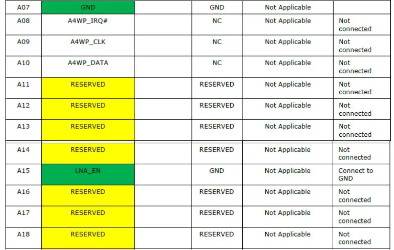
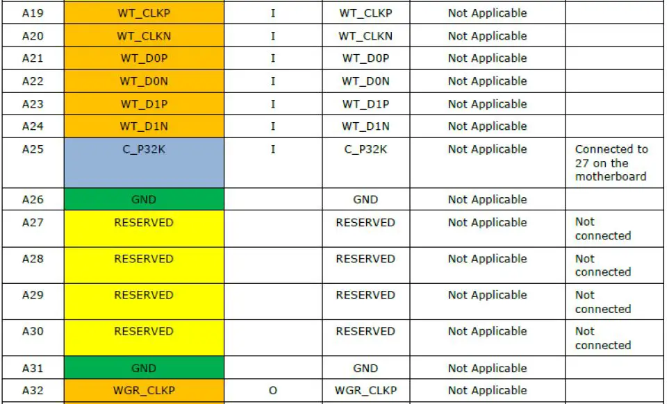
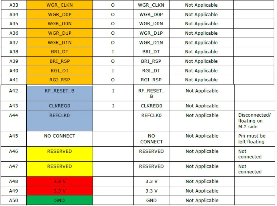
Pin No. Pin name In / Out Pin Voltage Description 1 UIM_POWER_ SRC/GPIO1 2 UIM_POWER_ SNK 3 UIM_SWP 4 3.3V 3.3V 5 3.3V 3.3V 6 GND 7 NFC_RESET# 8 ALERT# 9 I2C_CLK 10 I2C_DATA 11 COEX1 1.8V Coexistence with intel LTE 12 COEX2 1.8V Coexistence with intel LTE 13 COEX3 14 SYSCLK/GNSS0 15 TX_BLANKING/GNSS1 1.8V 16 RESERVED/VDDIO18 17 GND 18 RESERVED/ISH2_UART_RXD 19 RESERVED/ISH2_UART_TXD 20 GND 21 ISH1_UART_CTS 1.8V ISH-UART 22 ISH1_UART_RTS 1.8V ISH-UART 23 GND 24 ISH1_UART_RXD 1.8V ISH-UART 25 ISH1_UART_TXD 1.8V ISH-UART 26 GND 27 SUSCLK(32kHz) 3.3V 28 W_DISABLE1# 3.3V Wi-Fi On/Off 29 PEWAKE# 3.3V 30 CLKREQ# 3.3V PCI Clock Request 31 PERST# 3.3V PCI Reset 32 GND 33 REFCLKN0 PCI Reference Clock 34 REFCLKP0 PCI Reference Clock 35 GND 36 PETn0 PCI Tx 37 PETp0 PCI Tx 38 GND 39 PERn0 PCI Rx 40 PERp0 PCI Rx 41 GND 42 CLink_CLK Intel’s proprietary Wi-Fi host I/F for purpose of Active Manageability
43 CLink_DATA 44 CLink_RESET 3.3V 45 SDIO_RESET# SDIO not support in AX210 46 SDIO_WAKE# SDIO not support in AX210 47 SDIO_DATA3/WIGIG_UART_RXD SDIO not support in AX210 48 SDIO_DATA2/WIGIG_UART_TXD SDIO not support in AX210 49 SDIO_DATA1/WIGIG_UART_RTS SDIO not support in AX210 50 SDIO_DATA0/WIGIG_UART_CTS SDIO not support in AX210 51 SDIO_CMD SDIO not support in AX210 52 SDIO_CLK SDIO not support in AX210 53 UART_WAKE# UART not support in AX210 54 LPSS_UART_CTS UART not support in AX210 55 LPSS_UART_TXD UART not support in AX210 56 LPSS_UART_RXD UART not support in AX210 57 LPSS_UART_RTS UART not support in AX210 58 PCM_SYNC/I2S_WS PCM not support in AX210 59 PCM_IN/I2S_SD_IN PCM not support in AX210 60 PCM_OUT/I2S_SD_OUT PCM not support in AX210 61 PCM_CLK/I2S_SCK PCM not support in AX210 62 GND 63 W_DISABLE2# Bluetooth On/Off 64 LED2# Bluetooth Activity 65 LED1# Wi-Fi Activity 66 RESERVED/ISH2_UART_RTS 67 RESERVED/ISH2_UART_CTS 68 GND 69 USB_D- Bluetooth USB 70 USB_D+ Bluetooth USB 71 GND 72 3.3V 73 3.3V 74 GND 75 GND 76 GND 77 RESERVED 78 RESERVED 79 RESERVED 80 RESERVED 81 RESERVED 82 RESERVED 83 RESERVED 84 RESERVED 85 RESERVED 86 RESERVED 87 RESERVED 88 RESERVED 89 RESERVED 90 RESERVED 91 RESERVED 92 RESERVED 93 RESERVED 94 RESERVED 95 RESERVED 96 RESERVED A07~A50 NC Not used G1~G4 GND GG1~72 GND + Thermal Pad 


Power supply:
Requirement of Input Voltage is refer to the below table
| No | Item | Pin NO | Min | Typ | Max | Unit | Comments | |
| 1 | Supply Voltage | VCC | 4, 5 ,72, 73 | 3.135 | 3.3 | 3.465 | V | |
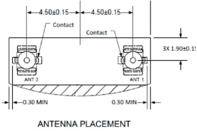
Antenna port
This is a description of the signal line of the antenna interface of this product.
| Pin number | Name | Functionality | ||
| Chain A | ANT 1 | SISO1 | Aux | Wifi+Bluetooth |
| Chain B | ANT 2 (ANT 3) | SISO2 | Main | Wifi Only |
Safety precautions:
This module should be used at authorized places or environments due to frequency jamming possibility while operating. If occur any issues when the module operates at not authorized places or environments, Samsung Electronics does not have any responsibility.
FCC Part 15 Information and Notices
This device complies with Part 15 of the FCC Rules. Operation is subject to the following two conditions:
- This device may not cause harmful interference, and
- this device must accept any interference received, including interference that may cause undesired operation.
This equipment has been tested and found to comply with the limits for a Class B digital device, pursuant to Part 15 of the FCC Rules. These limits are designed to provide reasonable protection against harmful interference in a residential installation. This equipment generates, uses and can radiate radio frequency energy and, if not installed and used in accordance with the instructions, may cause harmful interference to radio communications. However, there is no guarantee that interference will not occur in a particular installation. If this equipment does cause harmful interference to radio or television reception, which can be determined by turning the equipment off and on, the user is encouraged to try to correct the interference by one of the following measures:
- Reorient or relocate the receiving antenna.
- Increase the separation between the equipment and receiver.
- Connect the equipment into an outlet on a circuit different from that to which the receiver is connected.
- Consult the dealer or an experienced radio/TV technician for help. Any changes or modifications not expressly approved by the party responsible for compliance could void the user’s authority to operate this equipment. This transmitter must not be co-located or operating in conjunction with any other antenna or transmitter.
Important Notice to integrators
- This module is limited to OEM installation ONLY.
- This module is limited to installation in mobile or fixed applications, according to Part 2.1091(b).
- The separate approval is required for all other operating configurations, including portable configurations with respect to Part 2.1093 and different antenna configurations
- For FCC Part 15.31 (h) and (k): The host manufacturer is responsible for additional testing to verify complianceas a composite system. When testing the host device for compliance with Part15 Subpart B, the host manufacturer is required to show compliance with Part 15 Subpart B while the transmitter module(s) are installed and operating. The modules should be transmit and the evaluation should confirm that the module’s intentional emissions are compliant (i.e. fundamental and out of band emissions). The host manufacturer must verify that there are no additional unintentional emissions other than what is permitted in Part 15 Subpart B or emissions are complaint with the transmitter(s) rule(s). The Grantee will provide guidance to the host manufacturer for Part 15 B requirements if needed
End Product Labeling:
Due to the very small size of the AX211D2W, the marking has been placed in this user manual because theproduct label on the devices is considered too small to be readable. FCC ID : A3LAX211D730QED / IC : 649E-AX211730QED
Host system must be labeled with “Contains FCC ID : A3LAX211D730QED”, FCC ID displayed on label.and “Contains IC : 649E-AX211730QED, IC no. displayed on label.
Antenna Installation:
Only antennas of the same type and with equal or less gains as 3dBi for the 2.4GHz band and 5dBi for the5GHz require additional authorization for operation. For testing purposes the following dual band antenna that approximates closely the above limits was used:
Conditions To Be Observed By Use of 6 GHz Bands (5.925 GHz – 7.125GHz)
An indoor client device (6XD), where a client device is defined in FCC Part. 15.202, is limited to indoor locations and is under control of a low-power indoor access point (6ID) or subordinate(6PP). It is only possible to operate the client device can only operate under the control of a low-power indoor access point and subordinate. A client may initiate brief messages to associate with a low-power indoor access point or subordinate and establish a connection only after receiving a confirmation signal confirming that an AP is present and operating on a particular channel. After being associated, the indoor client can only initiate transmission with that access point. Indoor client devices (6XD) are prohibited from making a direct air interface connection to other clients. An indoor client device cannot have a direct connection to the internet.
Manual Information to the End User
The OEM integrator has to be aware not to provide information to the end user regarding how to install orremove this RF module in the user’s manual of the end product which integrates this module. The end usermanual shall include all required regulatory information/warning as show in this manual.
List of applicable FCC rules
This wireless adapter is restricted to indoor use due to its operation in the 5.15 to 5.25 and 5.470to 5.75GHz frequency ranges. No configuration controls are provided for Intel® wireless adapters allowing any change in the frequency of operations outside the FCC grant of authorization for U.S. operation according to Part 15.407 of the FCC rules.
- wireless adapters are intended for OEM integrators only.
- wireless adapters cannot be co-located with any other transmitter unless approved by the FCC
This device is intended only for OEM integratorsunder the following conditions: (For module device use)
- The antenna must be installed such that 20 cm is maintained between the antenna and users, and
- The transmitter module may not be co-located with any other transmitter or antenna. As long as 2 conditions above are met, further transmitter test will not be required. However, theOEM integrator is still responsible for testing their end-product for any additional compliance requirements required with this module installed.
RF Exposure Statement
The FCC with its action in ET Docket 96-8 has adopted a safety standard for human exposure to radio frequency(RF)electromagnetic energy emitted by FCC certified equipment. The wireless adapter meets the Human Exposure requirements found in FCC Part 2, 15C, 15E along with guidance from KDB 447498, KDB 248227 and KDB 616217. Proper operation of this radio according to the instructions found in this manual will result in exposure substantially below the FCC’s recommended limits.
The following safety precautions should be observed:
- Do not touch or move antenna while the unit is transmitting or receiving.
- Do not hold any component containing the radio such that the antenna is very close or touching any exposed parts of the body, especially the face or eyes, while transmitting.
- Do not operate the radio or attempt to transmit data unless the antenna is connected; this behavior may cause damage to the radio.
- Use in specific environments:
- The use of wireless adapters in hazardous locations is limited by the constraints posed by the safety directors of such environments.
- The use of wireless adapters on airplanes is governed by the Federal Aviation Administration (FAA).
- The use of wireless adapters in hospitals is restricted to the limits set forth by each hospital. This module will be installed into any host and SAR re-assessment might be needed for host product. The OEM or integrator is responsible to perform the required additional host regulatory testing and/or obtaining the required host approvals for compliance.


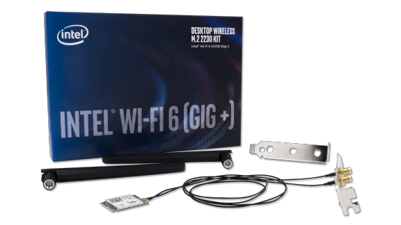
 Desktop Kit User Guide")


