![]()
MINiBOX 0-10V X3
Multifunction Actuator with 3 fold 0-10V analog input/output
ZIO3X010
USER MANUAL
INTRODUCTION
1.1 MINiBOX 0-10V X3
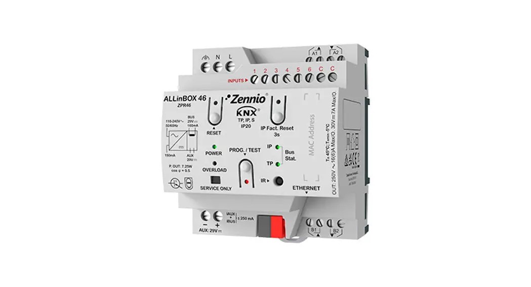
MINiBOX 0-10V X3 from Zennio is a KNX actuator that aims at fulfilling the climate control needs of KNX environments with integrated fan coil units where the valves in the pipes are controlled through analog 0-10 VDC signals. The actuator provides three analog outputs, which permit controlling one fan coil drive consisting of two or four pipes (each with its own valve) and a fan system.
- 1 fan coil analog module to control 2 and 4 pipes units with 0-10V fan or valves.
- 3 independent 0-10V analog voltage outputs configurable as fan or valve of a fan coil unit or another adjustable load between these voltage levels.
- 3 independent thermostats.
- 10 customizable, multi-operation logic functions.
- Manual operation/supervision of the outputs 0-10V through the onboard pushbuttons and LEDs.
- Heartbeat or periodical “still-alive” notification.
1.2 INSTALLATION
MINiBOX 0-10V X3 connects to the KNX bus through the onboard KNX connector.
Once the device is provided with power from the KNX bus, both the individual address and the associated application program may be downloaded.
This device does not need any additional external power since it is entirely powered through the KNX bus.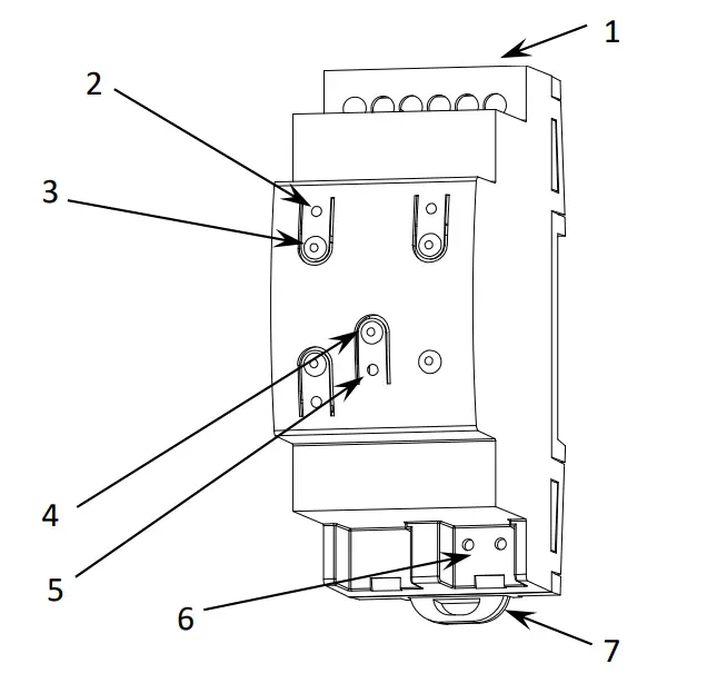
- Inputs/Outputs.
- 0-10V Output LED Indicator.
- 0-10V Output Manual Control Button
- Prog./Test Button.
- Prog./Test LED.
- KNX Connector.
- Fixing Clamp.
The main elements of the device are described next.
Test/Prog. Button (4): a short press on this button sets the device into the programming mode, making the associated LED (5) light in red.
Note: if this button is held while plugging the device into the KNX bus, the device will enter into safe mode. In such a case, the LED will blink in red every 0.5 seconds.
Outputs (1): output ports for the insertion of the stripped cables of the systems being controlled by the actuator (see section 2.3). Please secure the connection by means of the onboard screws.
To get detailed information about the technical features of this device, as well as on the installation and security procedures, please refer to the corresponding Datasheet, bundled with the original package of the device and also available at www.zennio.com.
1.3 START-UP AND POWER LOSS
Depending on the configuration, some specific actions will be performed during the startup. For example, the integrator can set whether the output channels should switch to a particular state and whether the device should send certain objects to the bus after the power recovery. Please consult the next sections of this document for further details.
On the other hand, when a bus power failure takes place, MINIBOX 0-10V X3 will interrupt any pending actions and will save its state so it can be recovered once the power supply is restored. Also, after failure recovery, the analog outputs and fan coil module will switch to the specific state configured in ETS (if any).
CONFIGURATION
2.1 GENERAL
After importing the corresponding database in ETS and adding the device into the topology of the project, the configuration process begins by entering the Parameters tab of the device.
ETS PARAMETERISATION
The only parameterisable screen that is always available is “General”. From this screen, it is possible to activate/deactivate all the required functionality.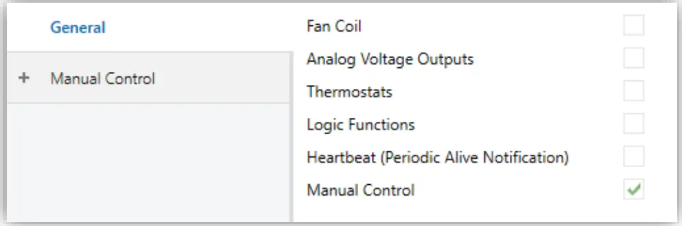
- Fan Coil [disabled/enabled]1: enables o disables the “Fan Coil” tab on the left menu. See section 2.2 for more details.
- Analog Voltage Outputs [disabled/enabled]: enables o disables the “Analog Voltage Outputs” tab on the left menu. See section 2.3 for more details.
- Thermostats [disabled/enabled]: enables o disables the “Thermostats” tab on the left menu. See section 2.4 for more details.
- Logic Functions [disabled/enabled]: enables o disables the “Logic Functions” tab on the left menu. See section 2.5 for more details
- MINiBOX 0-10V X3 Heartbeat (Periodical Alive Notification) [disabled/enabled]: this parameter lets the integrator incorporate a one-bit object to the project (“[Heartbeat] Object to Send `1′”) that will be sent periodically with value “1” to notify that the device is still working (still alive).
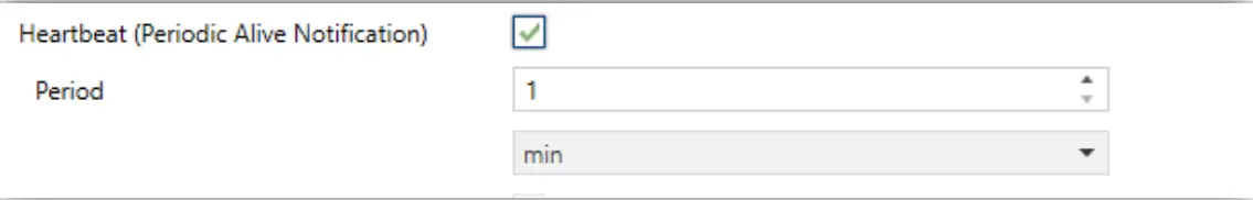
Figure 3. Heartbeat (Periodical Alive Notification).
Note: The first sending after download or bus failure takes place with a delay of up to 255 seconds, to prevent bus overload. The following sendings match the period set. Manual Control [disabled/enabled]: enables o disables the “Manual Control” tab on the left menu. See section 2.6 for more details.
2.2 FAN COIL
MINiBOX 0-10V X3 incorporates a module to control the fan and valves of a 2 or 4 pipes fan coil unit via its 0-10V analog voltage outputs.
Please refer to the specific user manual “Fan Coil `Analog'”, available in the MINiBOX 0-10V X3 product section, at the Zennio website (www.zennio.com) for detailed information about the functionality and the configuration of the related parameters.
2.3 ANALOG VOLTAGE OUTPUTS
The MINiBOX 0-10V X3 incorporates three 0-10V analog outputs which can be used to control fans and valves of a fan coil unit or other adjustable loads or generic outputs between these voltage levels.
Please refer to the specific user manual “Analog Voltage Output”, available in the MINiBOX 0-10V X3 product section, at the Zennio website (www.zennio.com) for detailed information about the functionality and the configuration of the related parameters.
2.4 THERMOSTATS
MINiBOX 0-10V X3 implements three Zennio thermostats which can be enabled and configured independently. Please refer to the specific “Zennio Thermostat” user manual (available in the MINiBOX 0-10V X3 product section at the Zennio homepage, www.zennio.com) for detailed information about the functionality and the configuration of the related parameters.
2.5 LOGIC FUNCTIONS
This module makes it possible to perform numeric and binary operations to incoming values received from the KNX bus, and to send the results through other communication objects specifically enabled for this purpose.
MINiBOX 0-10V X3 can implement up to 10 different and independent functions, each of them entirely customizable and consisting of up to 4 consecutive operations each.
The execution of each function can depend on a configurable condition, which will be evaluated every time the function is triggered through specific, parameterizable communication objects. The result after executing the operations of the function can also be evaluated according to certain conditions and afterward sent (or not) to the KNX bus, which can be done every time the function is executed, periodically or only when the result differs from the last one.
Please refer to the specific “Logic Functions” user manual (available in the MINiBOX 0-10V X3 product section at the Zennio homepage, www.zennio.com) for detailed information about the functionality and the configuration of the related parameters.
2.6 MANUAL CONTROL
MINiBOX 0-10V X3 enables manual control of the status of its output relays through the respective pushbuttons on the top of the device. A specific pushbutton is therefore available per output.
Manual operation can be done in two different ways, named as Test On Mode (for testing purposes during the configuration of the device) and Test Off Mode (for a normal use, anytime). Whether both, only one, or none of these modes can be accessed needs to be parameterised in ETS. Moreover, it is possible to enable a specific binary object for locking and unlocking the manual control in runtime.
Note:
- The Test Off mode will be active (unless it has been disabled by parameter) after a download or a reset with no need of a specific activation the pushbuttons will respond to user presses from the start.
- On the contrary, switching to the Test On mode (unless disabled by parameter) needs to be done by long-pressing the Prog./Test button (for at least three seconds), until the LED is no longer red and turns yellow. From that moment, once the button is released, the LED light will remain green to confirm that the device has switched from the Test Off mode to the Test On mode. After that, an additional press will turn the LED yellow and then off, once the button is released. This way, the device leaves the
- Test On mode. Note that it will also leave this mode if a bus power failure takes place or if a manual control lock is sent from the KNX bus.
Test Off Mode
Under the Test Off Mode, the outputs can be controlled through both their communication objects and the actual pushbuttons located on the top of the device.
When one of these buttons is pressed, the output will behave as if an order had been received through the corresponding communication object.
Individual voltage output: only the status of analog outputs configured as “generic outputs” can be controlled manually.
When the button is pressed, the device will act over the output according to the length of the button press and to the current state:
- Long press: action equivalent to a 0% or 100% control command in the output control object. The status is sent via the associated status object.
- Short press: initiates an increasing regulation if the output status is 0% at that time, or a decreasing regulation if it is 100%. For values between 0 and 100%, the control of regulation is switched with each long press. The status object will be sent to the bus after stopping the press or reaching the minimum or maximum value.
In Test Off mode, and press on the buttons of the outputs disabled by parameter will have no effect.
Test On Mode
After entering the Test On mode, it will only be possible to control the outputs through the on-board pushbuttons. Orders received through communication objects will be ignored, with the independence of the channel or the output they are addressed to.
- Individual output: the action performed on the output by pressing the physical buttons will be the same as described in the Test Off mode except that the status objects will not be affected.
Note: unlike in test on mode, in test off mode any type of output can be controlled, not only the generic ones.
Under the Test On mode, short and long presses will cause the same effect for disabled outputs as for analog voltage outputs.
As described previously if the device is in Test On mode, any command sent from the KNX bus to the actuator will not affect the outputs and no status objects will be sent (only periodically timed objects such as Heartbeat or logic functions will continue to be sent to the bus) while Test ON mode is active.
Important: the device is factory delivered with all the output channels configured as disabled outputs, and with both manual modes (Test Off and Test On) enabled.
ETS PARAMETERISATION
The Manual Control is configured from the “Configuration” sub-tab itself under “Manual Control”.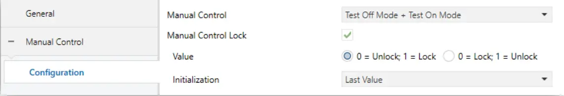
Figure 4. Manual control.
Manual Control [Disabled / Only Test Off Mode / Only Test On Mode / Test Off Mode + Test On Mode]: Depending on the selection, the device will permit using the manual control under the Test Off, the Test On, or both modes.
Note that, as stated before, using the Test Off mode does not require any special action, while switching to the Test On mode does require long-pressing the Prog./Test button.
Lock Manual Control [disabled /enabled]: unless the above parameter has been “Disabled”, the Lock Manual Control parameter provides an optional procedure for locking the manual control in runtime. When this checkbox is enabled, object “Manual Control Lock” turns visible, as well as two more parameters:
Value [0 = Lock; 1 = Unlock / 0 = Unlock; 1 = Lock]: defines whether the manual control lock/unlock should take place respectively upon the reception (through the aforementioned object) of values “0” and “1”, or the opposite.
Initialization [Unlocked / Locked / Last Value]: sets how the manual control should remain after the device start-up (after an ETS download or a bus power failure). “Last Value” (default; on the very first start-up, this will be Unlocked.
ANNEX I. COMMUNICATION OBJECTS
“Functional range” shows the values that, with the independence of any other values permitted by the bus according to the object size, may be of any use or have a particular meaning because of the specifications or restrictions from both the KNX standard or the application program itself.
| Number | Size | I/O | Flags | Data type (DPT) | Functional Range | Name | Function |
| 1 | 1 Bit | C – – T – | DPT_Trigger | 0/1 | [Heartbeat] Object to Send ‘1’ | Sending of ‘1’ Periodically | |
| 2 | 1 Bit | I/O | C R W – – | DPT_Enable | 0/1 | Manual Control Lock | 0 = Unlock; 1 = Lock |
| 1 Bit | I/O | C R W – – | DPT_Enable | 0/1 | Manual Control Lock | 0 = Lock; 1 = Unlock | |
| 3 | 1 Bit | I | C – W T U | DPT_Switch | 0/1 | [FCx] On/Off | 0 = Off; 1 = On |
| 4 | 1 Bit | O | C R – T – | DPT_Switch | 0/1 | [FCx] On/Off (Status) | 0 = Off; 1 = On |
| 5 | 1 Bit | I | C – W T U | DPT_Heat_Cool | 0/1 | [FCx] Mode | 0 = Cool; 1 = Heat |
| 6 | 1 Bit | O | C R – T – | DPT_Heat_Cool | 0/1 | [FCx] Mode (Status) | 0 = Cool; 1 = Heat |
| 7 | 1 Byte | I | C – W T U | DPT_Scaling | 0% – 100% | [FCx] Control Variable (Cooling) | 0 – 100% |
| 8 | 1 Byte | I | C – W T U | DPT_Scaling | 0% – 100% | [FCx] Control Variable (Heating) | 0 – 100% |
| 9 | 1 Byte | O | C R – T – | DPT_Scaling | 0% – 100% | [FCx] Cooling Valve: Control | 0 – 100% |
| 1 Byte | O | C R – T – | DPT_Scaling | 0% – 100% | [FCx] Valve: Control | 0 – 100% | |
| 10 | 1 Bit | O | C R – T – | DPT_Switch | 0/1 | [FCx] Cooling Valve: Anti-Seize Protection (Status) | 0 = Not Active; 1 = Active |
| 1 Bit | O | C R – T – | DPT_Switch | 0/1 | [FCx] Valve: Anti-Seize Protection (Status) | 0 = Not Active; 1 = Active | |
| 11 | 1 Byte | O | C R – T – | DPT_Scaling | 0% – 100% | [FCx] Heating Valve: Control | 0 – 100% |
| 12 | 1 Bit | O | C R – T – | DPT_Switch | 0/1 | [FCx] Heating Valve: Anti-Seize Protection (Status) | 0 = Not Active; 1 = Active |
| 13 | 1 Bit | I | C – W T U | DPT_Enable | 0/1 | [FCx] Fan: Manual/Automatic | 0 = Automatic; 1 = Manual |
| 1 Bit | I | C – W T U | DPT_Enable | 0/1 | [FCx] Fan: Manual/Automatic | 0 = Manual; 1 = Automatic | |
| 14 | 1 Bit | O | C R – T – | DPT_Enable | 0/1 | [FCx] Fan: Manual/Automatic (Status) | 0 = Automatic; 1 = Manual |
| 1 Bit | O | C R – T – | DPT_Enable | 0/1 | [FCx] Fan: Manual/Automatic (Status) | 0 = Manual; 1 = Automatic | |
| 15 | 1 Byte | O | C R – T – | DPT_Scaling | 0% – 100% | [FCx] Fan: Speed Control | 0 – 100% |
| 16 | 1 Byte | I | C -WTU | DPT_Scaling | 0% – 100% | [FCx] Manual Fan: Speed | 0 – 100% |
| 17 | 2 Bytes | I | C -WTU | DPT_TimePeriodMin | 0 – 65535 | [FCx] Manual Fan: Manual Control Duration | 0 = Endless; 1 – 1440 min |
| 2 Bytes | I | C – WTU | DPT_TimePeriodHrs | 0 – 65535 | [FCx] Manual Fan: Manual Control Duration | 0 = Endless; 1 – 24 h | |
| 18 | 1 Byte | I | C – WTU | DPT_Scaling | 0% – 100% | [FCx] Fan: Automatic Air Recirculation Speed | 0 – 100% |
| 19, 28, 37 | 1 Bit | I | C – W – – | DPT_Switch | 0/1 | [AOx] On/Off | 0 = Off; 1 = On |
| 20, 29, 38 | 1 Bit | O | C R – T – | DPT_Switch | 0/1 | [AOx] On/Off (Status) | 0 = Off; 1 = On |
| 21, 30, 39 | 4 Bit | I | C – W – – | DPT_Control_Dimming | 0x0 (Stop) 0x1 (Dec. by 100%) …0x7 (Dec. by 1%) 0x8 (Stop)0xD (Inc. by 100%) …0xF (Inc. by 1%) | [AOx] Relative Control | 4-bits dimmer control |
| 22, 31, 40 | 1 Byte | I | C – W T U | DPT_Scaling | 0% – 100% | [AOx] Absolute Control | 0 – 100 % |
| 23, 32, 41 | 1 Byte | O | C R – T – | DPT_Scaling | 0% – 100% | [AOx] Output (Status) | 0 – 100 % |
| 24, 33, 42 | 1 Bit | I | C – W – – | DPT_Switch | 0/1 | [AOx] Custom On/Off | 0 = Off; 1 = On |
| 25, 34, 43 | 1 Bit | I | C – W – – | DPT_Start | 0/1 | [AOx] Simple Timer | 0 = Deactivate; 1 = Activate |
| 26, 35, 44 | 1 Bit | I | C – W – – | DPT_Start | 0/1 | [AOx] Flashing | 0 = Deactivate; 1 = Activate |
| 27, 36, 45 | 1 Bit | I | C – W T U | DPT_Enable | 0/1 | [AOx] Lock | 0 = Unlock; 1 = Lock |
| 46 | 1 Byte | I | C – W – – | DPT_SceneControl | 0-63; 128-191 | [Thermostat] Scene Input | Scene Value |
| 47, 85, 123 | 2 Bytes | I | C – W T U | DPT_Value_Temp | -273.00º – 670433.28º | [Tx] Temperature Source 1 | External Sensor Temperature |
| 48, 86, 124 | 2 Bytes | I | C – W T U | DPT_Value_Temp | -273.00º – 670433.28º | [Tx] Temperature Source 2 | External Sensor Temperature |
| 49, 87, 125 | 2 Bytes | O | C R – T – | DPT_Value_Temp | -273.00º – 670433.28º | [Tx] Effective Temperature | Effective Control Temperature |
| 50, 88, 126 | 1 Byte | I | C – W – – | DPT_HVACMode | 1=Comfort 2=Standby 3=Economy 4=Building Protection | [Tx] Special Mode | 1-Byte HVAC Mode |
| 51, 89, 127 | 1 Bit | I | C – W – – | DPT_Ack | 0/1 | [Tx] Special Mode: Comfort | 0 = Nothing; 1 = Trigger |
| 1 Bit | I | C – W – – | DPT_Switch | 0/1 | [Tx] Special Mode: Comfort | 0 = Off; 1 = On | |
| 52, 90, 128 | 1 Bit | I | C – W – – | DPT_Ack | 0/1 | [Tx] Special Mode: Standby | 0 = Nothing; 1 = Trigger |
| 1 Bit | I | C – W – – | DPT_Switch | 0/1 | [Tx] Special Mode: Standby | 0 = Off; 1 = On | |
| 53, 91, 129 | 1 Bit | I | C – W – – | DPT_Ack | 0/1 | [Tx] Special Mode: Economy | 0 = Nothing; 1 = Trigger |
| 1 Bit | I | C – W – – | DPT_Switch | 0/1 | [Tx] Special Mode: Economy | 0 = Off; 1 = On | |
| 54, 92, 130 | 1 Bit | I | C – W – – | DPT_Ack | 0/1 | [Tx] Special Mode: Protection | 0 = Nothing; 1 = Trigger |
| 1 Bit | I | C – W – – | DPT_Switch | 0/1 | [Tx] Special Mode: Protection | 0 = Off; 1 = On | |
| 55, 93, 131 | 1 Bit | I | C – W – – | DPT_Window_Door | 0/1 | [Tx] Window Status (Input) | 0 = Closed; 1 = Open |
| 56, 94, 132 | 1 Bit | I | C – W – – | DPT_Trigger | 0/1 | [Tx] Comfort Prolongation | 0 = Nothing; 1 = Timed Comfort |
| 57, 95, 133 | 1 Byte | O | C R – T – | DPT_HVACMode | 1=Comfort 2=Standby 3=Economy 4=Building Protection | [Tx] Special Mode Status | 1-Byte HVAC Mode |
| 58, 96, 134 | 2 Bytes | I | C – W – – | DPT_Value_Temp | -273.00º – 670433.28º | [Tx] Setpoint | Thermostat Setpoint Input |
| 2 Bytes | I | C – W – – | DPT_Value_Temp | -273.00º – 670433.28º | [Tx] Basic Setpoint | Reference Setpoint | |
| 59, 97, 135 | 1 Bit | I | C – W – – | DPT_Step | 0/1 | [Tx] Setpoint Step | 0 = Decrease Setpoint; 1 = Increase Setpoint |
| 60, 98, 136 | 2 Bytes | I | C – W – – | DPT_Value_Tempd | -671088.64º – 670433.28º | [Tx] Setpoint Offset | Float Offset Value |
| 61, 99, 137 | 2 Bytes | O | C R – T – | DPT_Value_Temp | -273.00º – 670433.28º | [Tx] Setpoint Status | Current Setpoint |
| 62, 100, 138 | 2 Bytes | O | C R – T – | DPT_Value_Temp | -273.00º – 670433.28º | [Tx] Basic Setpoint Status | Current Basic Setpoint |
| 63, 101, 139 | 2 Bytes | O | C R – T – | DPT_Value_Tempd | -671088.64º – 670433.28º | [Tx] Setpoint Offset Status | Current Setpoint Offset |
| 64, 102, 140 | 1 Bit | I | C – W – – | DPT_Reset | 0/1 | [Tx] Setpoint Reset | Reset Setpoint to Default |
| 1 Bit | I | C – W – – | DPT_Reset | 0/1 | [Tx] Offset Reset | Reset Offset | |
| 65, 103, 141 | 1 Bit | I | C – W – – | DPT_Heat_Cool | 0/1 | [Tx] Mode | 0 = Cool; 1 = Heat |
| 66, 104, 142 | 1 Bit | O | C R – T – | DPT_Heat_Cool | 0/1 | [Tx] Mode Status | 0 = Cool; 1 = Heat |
| 67, 105, 143 | 1 Bit | I | C – W – – | DPT_Switch | 0/1 | [Tx] On/Off | 0 = Off; 1 = On |
| 68, 106, 144 | 1 Bit | O | C R – T – | DPT_Switch | 0/1 | [Tx] On/Off Status | 0 = Off; 1 = On |
| 69, 107, 145 | 1 Bit | I/O | C R W – – | DPT_Switch | 0/1 | [Tx] Main System (Cool) | 0 = System 1; 1 = System 2 |
| 70, 108, 146 | 1 Bit | I/O | C R W – – | DPT_Switch | 0/1 | [Tx] Main System (Heat) | 0 = System 1; 1 = System 2 |
| 71, 109, 147 | 1 Bit | I | C – W – – | DPT_Enable | 0/1 | [Tx] Enable/Disable Secondary System (Cool) | 0 = Disable; 1 = Enable |
| 72, 110, 148 | 1 Bit | I | C – W – – | DPT_Enable | 0/1 | [Tx] Enable/Disable Secondary System (Heat) | 0 = Disable; 1 = Enable |
| 73, 79, 111, 117, 149, 155 | 1 Byte | O | C R – T – | DPT_Scaling | 0% – 100% | [Tx] [Sx] Control Variable (Cool) | PI Control (Continuous) |
| 74, 80, 112, 118, 150, 156 | 1 Byte | O | C R – T – | DPT_Scaling | 0% – 100% | [Tx] [Sx] Control Variable (Heat) | PI Control (Continuous) |
| 1 Byte | O | C R – T – | DPT_Scaling | 0% – 100% | [Tx] [Sx] Control Variable | PI Control (Continuous) | |
| 75, 81, 113, 119, 151, 157 | 1 Bit | O | C R – T – | DPT_Switch | 0/1 | [Tx] [Sx] Control Variable (Cool) | 2-Point Control |
| 1 Bit | O | C R – T – | DPT_Switch | 0/1 | [Tx] [Sx] Control Variable (Cool) | PI Control (PWM) | |
| 76, 82, 114, 120, 152, 158 | 1 Bit | O | C R – T – | DPT_Switch | 0/1 | [Tx] [Sx] Control Variable (Heat) | 2-Point Control |
| 1 Bit | O | C R – T – | DPT_Switch | 0/1 | [Tx] [Sx] Control Variable (Heat) | PI Control (PWM) | |
| 1 Bit | O | C R – T- | DPT_Switch | 0/1 | [Tx] [Sx] Control Variable | 2-Point Control | |
| 1 Bit | O | C R – T- | DPT_Switch | 0/1 | [Tx] [Sx] Control Variable | PI Control (PWM) | |
| 77, 83, 115, 121, 153, 159 | 1 Bit | O | C R – T- | DPT_Switch | 0/1 | [Tx] [Sx] PI State (Cool) | 0 = PI Signal 0%; 1 = PI Signal Greater than 0% |
| 78, 84, 116, 122, 154, 160 | 1 Bit | O | C R – – | DPT_Switch | 0/1 | [Tx] [Sx] PI State (Heat) | 0 = PI Signal 0%; 1 = PI Signal Greater than 0% |
| 1 Bit | O | C R – T – | DPT_Switch | 0/1 | [Tx] [Sx] PI State | 0 = PI Signal 0%; 1=PISignal Greater than | |
| 161, 162, 163, 164, 165166, 167, 168, 169, 170,171, 172, 173, 174, 175,176, 177, 178, 179, 180,181, 182, 183, 184, 185,186, 187, 188,189,190,191, 192 | 1 Bit | I | C – W – – | DPT_Bool | 0/1 | [LF] (1-Bit) Data Entry x | Binary Data Entry (0/1) |
| 193, 194, 195, 196, 197,198, 199, 200, 201, 202,203, 204, 205, 206, 207,208 | Byte | I | C – W – – | DPT_Value_1_Ucount | 0 – 255 | [LF] (1-Byte) Data Entry | 1-Byte Data Entr (-255) |
| 209, 210,211,212,213,214, 215, 216, 217, 218,219, 220, 221, 222, 223,224 | 2 Bytes | I | C – W – – | DPT_Value_2_Ucount | 0 – 65535 | [LF] (2-Byte) Data Entry x | 2-Byte Data Entry |
| 225, 226, 227, 228, 229,230, 231, 232 | 4 Bytes | I | C – W – – | DPT_Value_4_Count | -2147483648 -2147483647 | [LF] (4-Byte) Data Entry x | 4-Byte Data Entry |
| 233, 234, 235, 236, 237, 238, 239, 240, 241, 242 | 1 Bit | O | C R – T – | DPT_Bool | 0/1 | [LF] Function x – Result | (1-Bit) Boolean |
| 1 Byte | O | C R – T – | DPT_Value_1_Ucount | 0 – 255 | [LF] Function x – Result | (1-Byte) Unsigned | |
| 2 Bytes | O | C R – T – | DPT_Value_2_Ucount | 0 – 65535 | [LF] Function x – Result | (2-Byte) Unsigned | |
| 4 Bytes | O | C R – T – | DPT_Value_4_Count | -2147483648 – 2147483647 | [LF] Function x – Result | (4-Byte) Signed | |
| 1 Byte | O | C R – T – | DPT_Scaling | 0% – 100% | [LF] Function x – Result | (1-Byte) Percentage | |
| 2 Bytes | O | C R – T- | DPT_Value_2_Count | -32768 – 32767 | [LF] Function x – Result | (2-Byte) Signed | |
| 2Bytes | O | C R – T- | 9.xxx | -671088.64 – 670433.28 | [LF] Function x – Result | (2-Byte) Float |
https://www.zennio.com
Technical Support: https://support.zennio.com 18
Join and send us your inquiries about Zennio devices: https://support.zennio.com
Zennio Avance y Tecnología S.L. C/ Río
Jarama, 132. Nave P-8.11 45007
Toledo (Spain).
Tel. +34 925 232 002.
www.zennio.com
i[email protected]


