![]() 3-Way Mixing Valve and 58131 Actuator Installation
3-Way Mixing Valve and 58131 Actuator Installation
www.heatlink.com
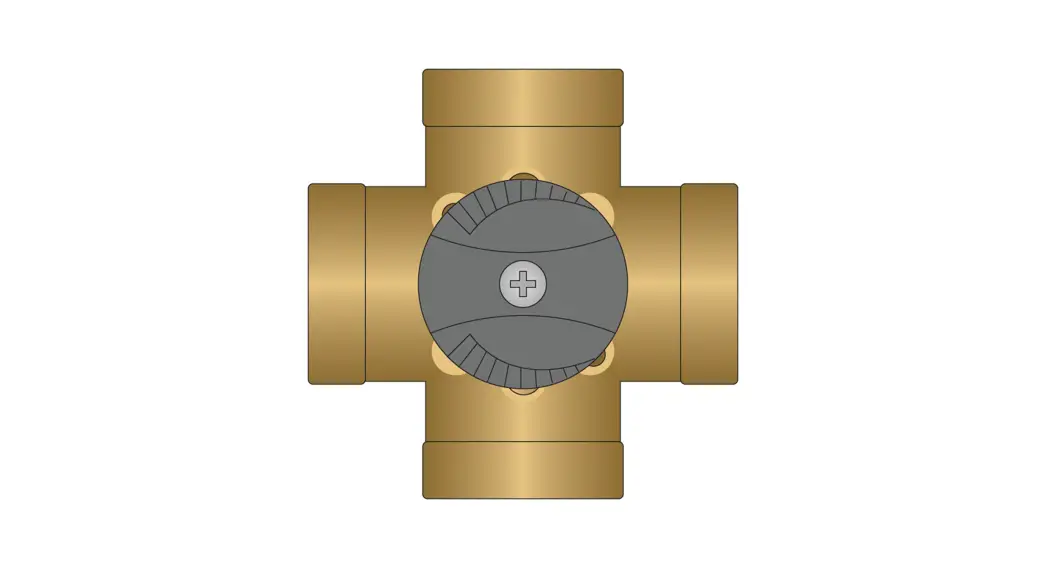
Mixing Valve Installation The 3-way valve can be used for mixing or diverting. This guide is for mixing applications only.
- In 3-way mixing applications, there are two inlets (supply from the boiler, return from a slab) and a single outlet (mixed fluid). See diagram for details.
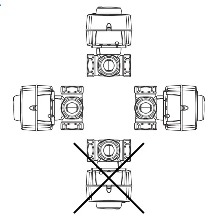
- The valve can be mounted horizontally or vertically.
Note: The valve must not be mounted upside down as this can cause actuator malfunctions in the event of a leaky valve. 
 Determine the orientation that best suits your system piping.
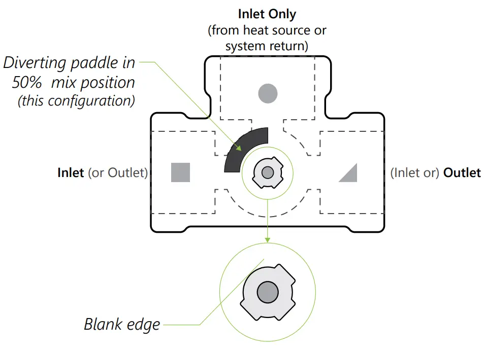
- Set the valve to the 50% mix position, with the indicator on the knob (or the blank edge of the stem) facing halfway between the two inlets. You can use the markings on the valve as a reference when piping.
Use these diagrams as an example of possible valve orientations and to see how the piping and valve orientation affects the diverting paddle position. Schematic simplified for illustration purposes; not all components are shown.All information is subject to change without notice.
Please check our website to ensure you have the latest version of this document.
Mounting the 58131 Actuator
3-Way Mixing Valve and 58131 Actuator Installation - Check that you have the proper actuator: 58131 (ESBE part# ARA663)
- Check all accessories are included with the actuator.
 Remove and dispose of the factory-mounted knob. Ensure position is still at 50% mix.
Proper orientation with “flat” top of the valve stem at 50% mix position.
Note: The position of your valve may be different depending on piping.
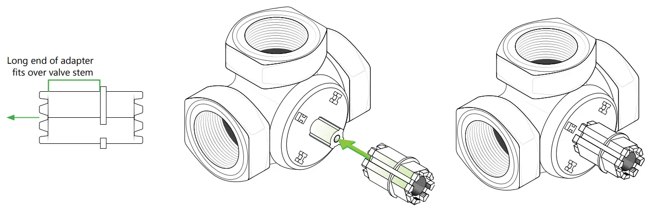
- Attach the plastic adapter included in the 58131 package to the valve stem. The flat spot on the adapter will line up with the flat spot on the stem.

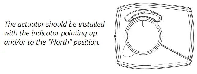
- Mount the 58131 actuator motor onto the valve – for readability, it is best to mount the actuator motor as shown in the diagrams, (with the indicator at the “north” position) regardless of the valve orientation. The factory setting is at 50% mix. DO NOT change the position of the knob as this may lead to improper operation of the valve.
 a. Remove the knob by pulling it straight out.
b. Secure the actuator motor to the valve using the included screw.
c. Replace the indicator knob. d. Ensure the correct indicator tab is installed on the actuator.
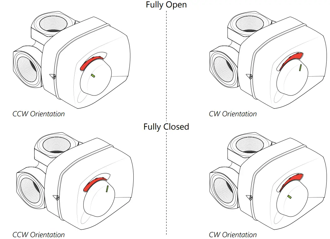
Choose the Clockwise indicator tab if the diverting paddle must rotate right (clockwise) to close the Return inlet. Choose the Counterclockwise indicator tab if the diverting paddle must rotate left (counterclockwise) to close the Return inlet.
From Heat Source Return from Slab Mix|
Illustrations are to be used as reference; not all valve orientations are represented.
e. Ensure the knob is in the AUTO position. If not, turn the knob and push in until it “clicks” into place – no red should be visible around the base.
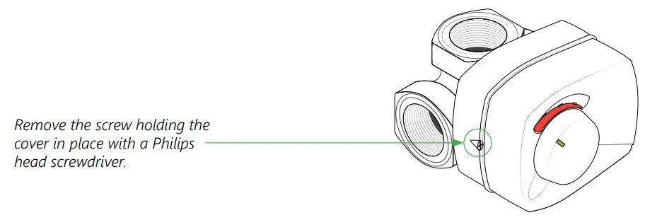
- Remove the cover.

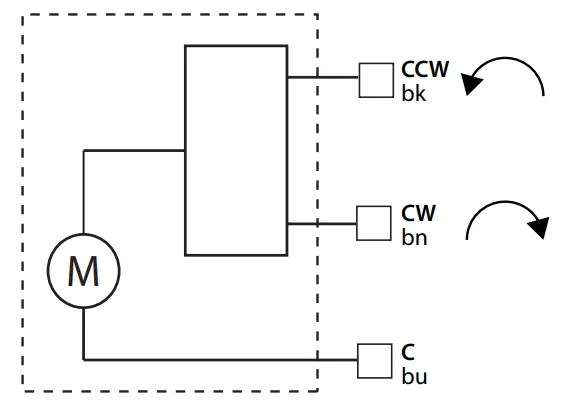
- Wire the actuator to the controller (no power)
a. Black = CCW
b. Brown = CW
c. Blue = C - Power up the controller and the actuator.
Note: Do Not apply power to the actuator until it has been properly mounted to the valve as this may damage the internal workings of the actuator.
- The actuator will move to fully open or fully closed from the default 50% open position depending on what the controller requests. Fully Open
 Determine the orientation that best suits your system piping.
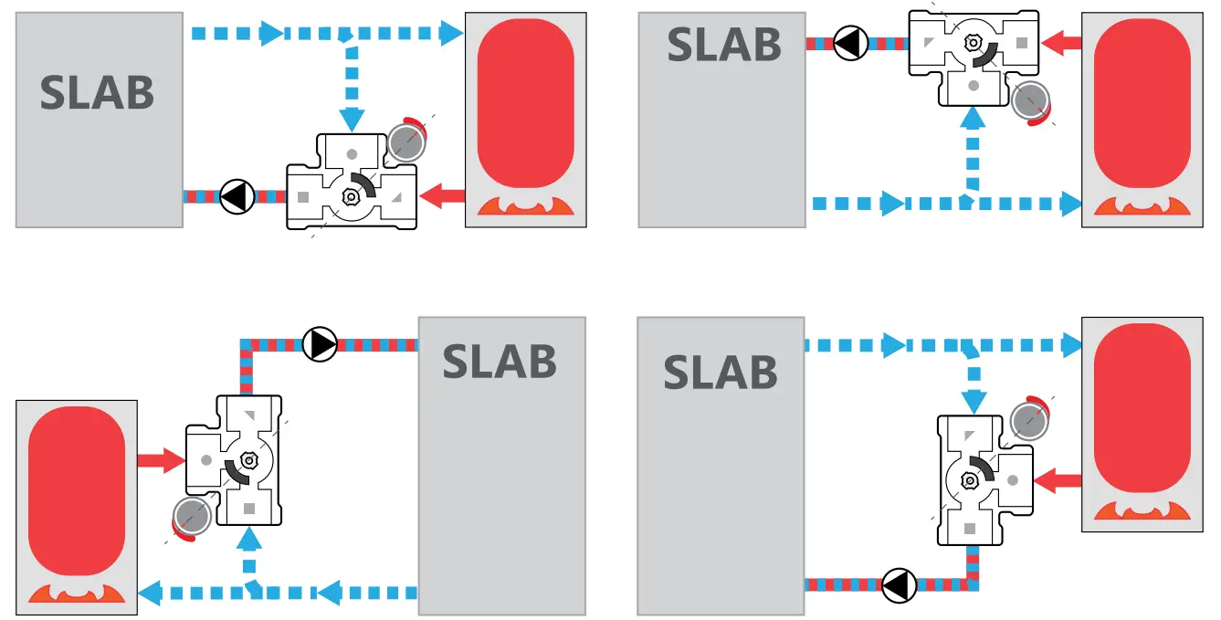 Schematic simplified for illustration purposes; not all components are shown.All information is subject to change without notice.
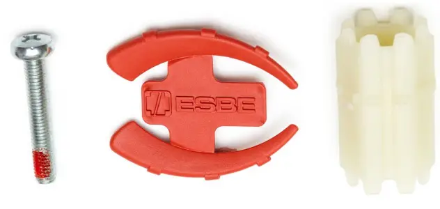 Remove and dispose of the factory-mounted knob. Ensure position is still at 50% mix.
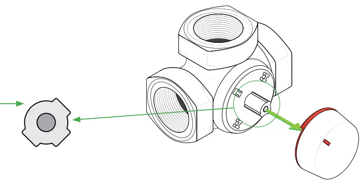
 a. Remove the knob by pulling it straight out.
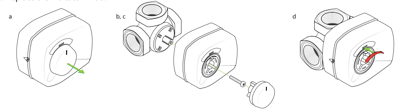 d. Ensure the correct indicator tab is installed on the actuator.
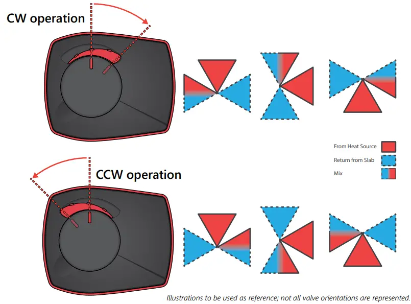 Choose the Counterclockwise indicator tab if the diverting paddle must rotate left (counterclockwise) to close the Return inlet.
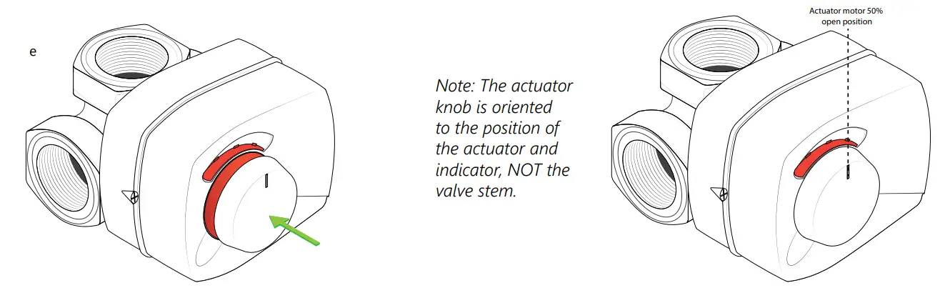
All information is subject to change without notice.
Please check our website to ensure you have the latest version of this document.
L6581313W
March 30, 2021


