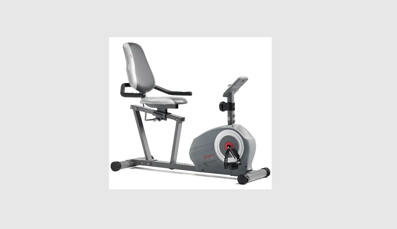
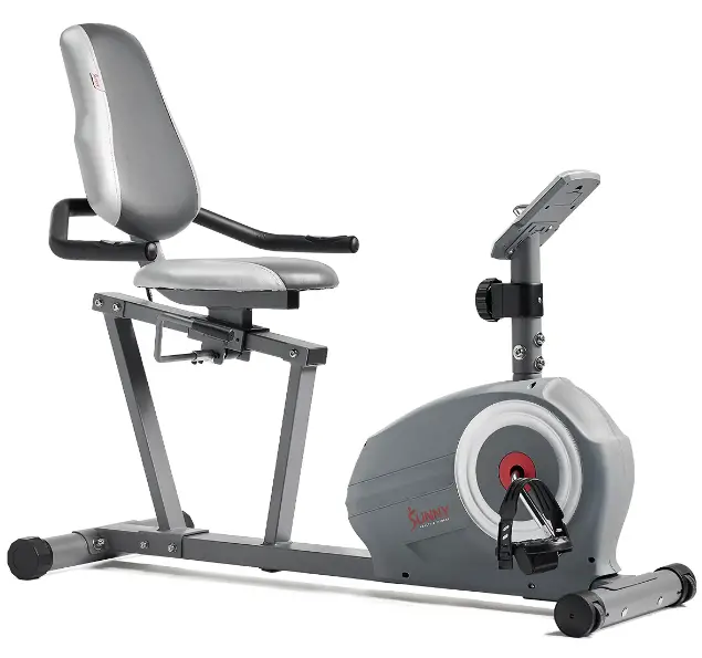
SUNNY SF-RB422003 ESSENTIAL INTERACTIVE RECUMBENT BIKE
IMPORTANT! Please retain owner’s manual for maintenance and adjustment instructions. Your satisfaction is very important to us, PLEASE DO NOT RETURN UNTIL YOU HAVE CONTACTED US: [email protected] or 1- 877 – 90SUNNY (877-907-8669).
IMPORTANT SAFETY INFORMATION
We thank you for choosing our product. To ensure your safety and health, please use this equipment correctly. It is important to read this entire manual before assembling and using the equipment. Safe and effective use can only be achieved if the equipment is assembled, maintained and used properly. It is your responsibility to ensure that all users of the equipment are informed of all warnings and precautions.
- Before starting any exercise program you should consult your physician to determine if you have any medical or physical conditions that could put your health and safety at risk, or prevent you from using the equipment properly. Your physician’s advice is essential if you are taking medication that affects your heart rate, blood pressure or cholesterol level.
- Be aware of your body’s signals. Incorrect or excessive exercise can damage your health. Stop exercising if you experience any of the following symptoms: pain, tightness in your chest, irregular heartbeat, shortness of breath, lightheadedness, dizziness or feelings of nausea. If you do experience any of these conditions, you should consult your physician before continuing with your exercise program.
- Keep children and pets away from the equipment. The equipment is designed for adult use only.
- Use the equipment on a solid, flat level surface with a protective cover for your floor or carpet. To ensure safety, the equipment should have at least 4 feet (1.2 M) of free space all around it.
- Ensure that all nuts and bolts are securely tightened before using the equipment. The safety of the equipment can only be maintained if it is regularly examined for damage and/or wear and tear.
- Always use the equipment as indicated. If you find any defective components while assembling or checking the equipment, or if you hear any unusual noises coming from the equipment during exercise, discontinue use of the equipment immediately and do not use until the problem has been rectified.
- Wear suitable clothing while using the equipment. Avoid wearing loose clothing that may become entangled in the equipment.
- Do not place fingers or objects into the moving parts of the equipment
- The maximum weight capacity of this unit is 220 pounds (100 KG).
- The equipment is not suitable for therapeutic use.
- Use caution when lifting and moving the equipment. Always use proper lifting technique and seek assistance if necessary.
- Your product is intended for use in cool, dry conditions. You should avoid storage in extreme cold, hot or damp areas as this may lead to corrosion and other related problems.
- This equipment is designed for indoor and home use only! It is not intended for commercial use!
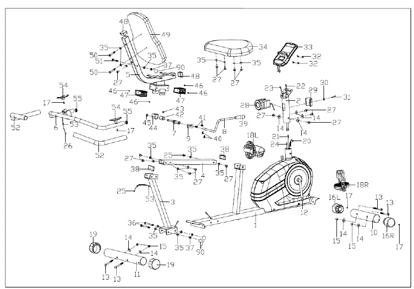
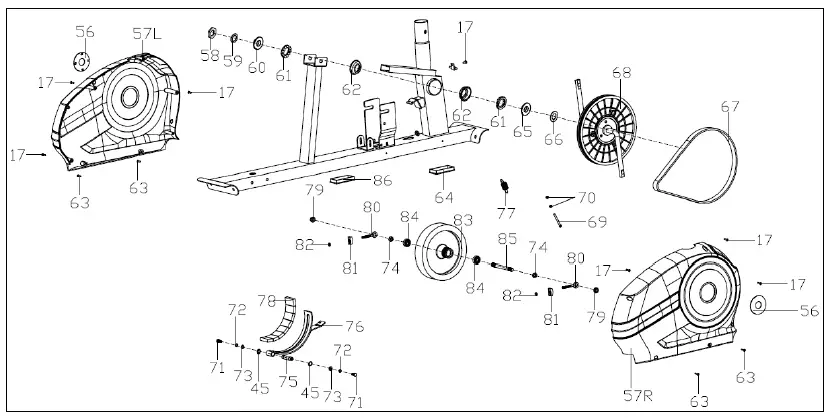
EXPLODED DIAGRAM
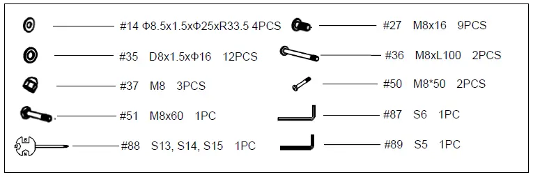
HARDWARE PACKAGE
Ordering Replacement Parts (U.S. and Canadian Customers only)
Please provide the following information in order for us to accurately identify the part(s) needed:
- The model number (found on cover of manual)
- The product name (found on cover of manual)
- The part number found on the “EXPLODED DIAGRAM” and “PARTS LIST” (found near the front of the manual)
Please contact us at [email protected] or 1.-.877.-.90SUNNY (877-907-8669).
PARTS LIST
| No. | Description | Spec. | Qty. | No. | Description | Spec. | Qty. | |
| 1 | Main Frame | 1 | 46 | Cross Pan Head Self-Drilling Screw | ST3.5×8 | 4 | ||
| 2 | Handlebar Post | 1 | 47 | Bushing | 2 | |||
| 3 | Rear Support Tube | 1 | 48 | Square Bushing | 2 | |||
| 4 | Slide Rail | 1 | 49 | Backrest | 1 | |||
| 5 | Seat Tube | 1 | 50 | Hex Socket Pan Head Screw | M8x50 | 2 | ||
| 6 | Handlebar | 1 | 51 | Carriage Bolt | M8x60 | 1 | ||
| 7 | Adjustment Block Axle | 1 | 52 | Foam Grip | 2 | |||
| 8 | Adjustment Handle | 1 | 53 | Wire Plug | 2 | |||
| 9 | Fixed Plate 3 | 1 | 54 | Pulse Plate | 2 | |||
| 10 | Front Stabilizer | 1 | 55 | Round Plug | 2 | |||
| 11 | Rear Stabilizer | 1 | 56 | Crank Cover | 2 | |||
| 12 | Crank | 1 | 57L/R | Chain Cover | 1pr. | |||
| 13 | Carriage Bolt | M8xL74 | 4 | 58 | Nut | 1 | ||
| 14 | Arc Washer | Ф8.5×1.5xФ25xR 33.5 | 8 | 59 | Washer | 1 | ||
| 15 | Cap Nut | M8 | 4 | 60 | Two-Slot Nut | 1 | ||
| 16L/R | Front End Cap | 1pr. | 61 | Ball Rack | 2 | |||
| 17 | Cross Pan Head Self-Drilling Screw | ST4.2×18 | 11 | 62 | Axle Bowl | 2 | ||
| 18L/R | Pedal | 1pr. | 63 | Hex Socket Pan Head Screw | ST5x20 | 4 | ||
| 19 | Rear End Cap | 2 | 64 | Square Plug | 1 | |||
| 20 | Tension Hook | 1 | 65 | Three-Slot Nut | 1 | |||
| 21 | Sensor Wire | 1 | 66 | Big Flat Washer | 1 | |||
| 22 | Sensor Connecting Wire | 1 | 67 | Belt | 1 | |||
| 23 | Pulse Connecting Wire 1 | 1 | 68 | Belt Pulley | 1 | |||
| 24 | Pulse Connecting Wire 2 | 1 | 69 | Hex Bolt | M5x60 | 1 | ||
| 25 | Pulse Connecting Wire 3 | 1 | 70 | Hex Screw | M5 | 2 | ||
| 26 | Pulse Wire | 1 | 71 | Hex Bolt | M6xL15 | 2 | ||
| 27 | Screw | M8x16 | 15 | 72 | Spring Washer | Ф6 | 2 | |
| 28 | Tension Controller | 1. | 73 | Flat Washer | D6 | 2 | ||
| 29 | Rear Cover | 1 | 74 | Conical Thin Nut | M10x1 | 2 | ||
| 30 | Flat Washer | 1 | 75 | Magnetic Board Axle | 1 | |||
| 31 | Screw | 1 | 76 | Magnetic Board | 1 | |||
| 32 | Screw | 4 | 77 | Tension Spring | 1 | |||
| 33 | Meter | 1 | 78 | Square Magnet | 8 | |||
| 34 | Seat | 1 | 79 | Flange Nut | M10x1 | 2 | ||
| 35 | Flat Washer | D8x1.5xФ16 | 18 | 80 | Adjustment Chain Bolt | M6x50 | 2 | |
| 36 | Hex Socket Pan Head Screw | M8x100 | 2 | 81 | Adjustment Chain U Mat | 2 | ||
| 37 | Nylon Nut | M8 | 3 | 82 | Hex Screw | M6 | 2 | |
| 38 | Square Cap | 2 | 83 | Flywheel | 1 | |||
| 39 | Fixed Handlebar Glove | 1 | 84 | Bearing | 6000 | 2 | ||
| 40 | Screw | M6x10 | 2 | 85 | Flywheel Axle | 1 | ||
| 41 | Screw | M6x16 | 2 | 86 | Square Plug | 1 | ||
| 42 | Eccentric Wheel | 1 | 87 | Allen Wrench | S6 | 1 | ||
| 43 | Screw | M8x10 | 1 | 88 | Spanner | S13,S14,S15 | 1 | |
| 44 | Upper Block | 1 | 89 | Allen Wrench | S5 | 1 | ||
| 45 | Axle Spring Washer | D12 | 3 | 90 | Cap | S13 | 3 |
ASSEMBLY INSTRUCTIONS
We value your experience using Sunny Health and Fitness products. For assistance with parts or troubleshooting, please contact us at [email protected] or 1-877-90SUNNY (877-907- 8669).
STEP 1
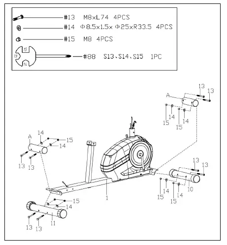
Remove the preassembled 4 Carriage Bolts (No. 13), 4 Arc Washers (No. 14) and 4 Cap Nuts (No. 15) from 2 Paper Tubes (No. A) with Spanner (No. 88)
Attach the Front Stabilizer (No. 10) and the Rea r Stabilizer (No. 11) to the Main Frame (No. 1) with 4 Carriage Bolts (No. 13), 4 Arc Washers (No. 14) and 4 Cap Nuts (No. 15) that were just removed using Spanner (No. 88).
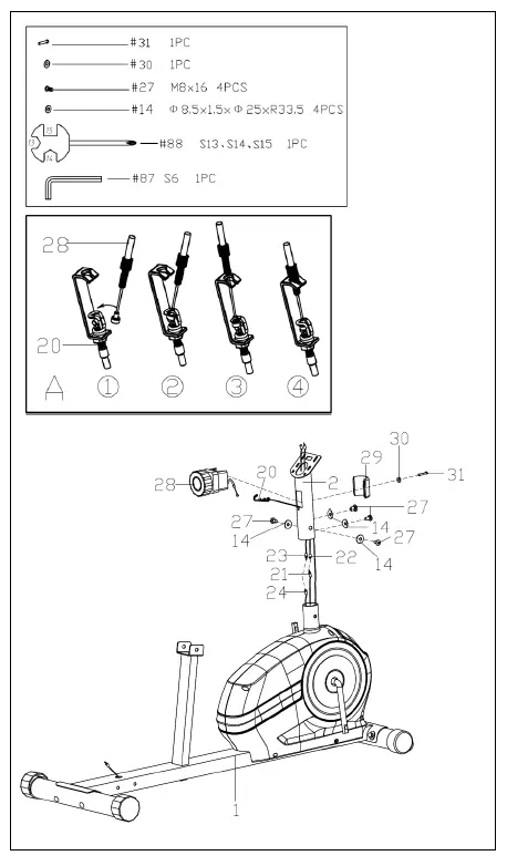
STEP 2
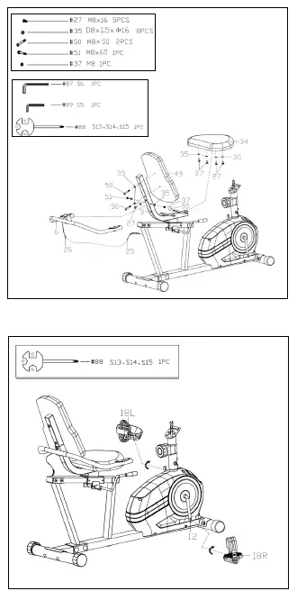
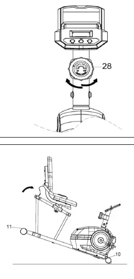
 Connect the Pulse Connecting Wire 1 (No. 23) to the Pulse Connecting Wire 2 (No. 24) and connect the Sensor Wire (No. 21) to the Sensor Conne cting Wire (No. 22). Insert the Tension Hook (No. 20) from the Main Frame (No. 1) to the inside tube of the Han dlebar Post (No. 2), then pull it out of the hole on the Handlebar Post (No. 2). Finally connect Tension Hook (No. 20) with Tension Controller (No. 28) as shown in Diagram A.
Note: Make sure the Tension Controller (No. 28) is at the lowest level before you connect the cable. This ensures the wires are at their longest point. We recommend the assistance of a second person to help hold the Handlebar Post (No. 2). This will make the connection easier when you are attaching Tension Hook (No. 20) to the cable.- Remove the preassembled Rear Cover (No. 29), Flat Washer (No. 30) and Screw (No. 31) from the Tension Controller (No. 28) with Spanner (No. 88). Lock the Tension Controller (No. 28) to the Handlebar Post (No. 2) with the Rear Cover (No. 29), Flat Washer (No. 30) and Screw (No. 31) with Spanner (No. 88).
- Insert the Handlebar Post (No. 2) into the post of the Main Frame (No. 1); secure with 4 Arc Washers (No. 14) and 4 Screws (No. 27) with Allen Wrench (No. 87).
Note: Ensure that all bolts and washers are in place and partially threaded in before completely tightening any of them.
 Connect the Pulse Connecting Wire 1 (No. 23) to the Pulse Connecting Wire 2 (No. 24) and connect the Sensor Wire (No. 21) to the Sensor Conne cting Wire (No. 22). Insert the Tension Hook (No. 20) from the Main Frame (No. 1) to the inside tube of the Han dlebar Post (No. 2), then pull it out of the hole on the Handlebar Post (No. 2). Finally connect Tension Hook (No. 20) with Tension Controller (No. 28) as shown in Diagram A.
STEP 3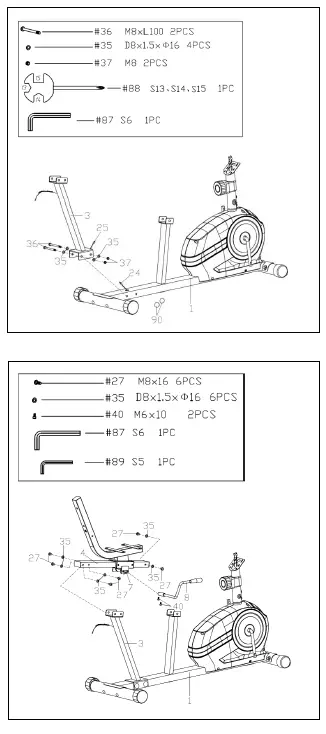
Connect the Pulse Connecting Wire 2 (No. 24) and Pulse Connecting Wire 3 (No. 25).
Lock the Rear S upport Tube (No. 3) to the Main Frame (No. 1) with 2 Hex Socket Pan Head Screws (No. 36), 4 Flat Washers (No. 35) and 2 Nylon Nuts (No. 37) with the Spanner (No. 88) and Allen Wrench (No. 87). Then cover with 2 Caps (No. 90)
Note: Do not damage any wires when locking the Rear Support Tube (No. 3) to the Main Frame (No. 1).
STEP 4
Remove the preassembled 6 Screws (No. 27) and 6 Flat Washers (No. 35) from the Slide Rail (No. 4) using Allen Wrench (No. 87). Then lock the Slide Rail (No. 4) to the Rear Support Tube (No. 3) and the Main Frame (No. 1) with 6 Screws (No. 27) and 6 Flat Washers (No. 35) that were just removed using Allen Wrench (No. 87).
Remove 2 Screws (No. 40) from the Adjustment Handle (No. 8) using Allen Wrench (No. 89), then lock the Adjustment Handle (No. 8) to the Adjustment Block Axle (No. 7) with 2 Screws (No. 40) using Allen Wrench (No. 89).
STEP 5
Lock the Seat (No. 34) to the Seat Tube (No. 5) with 4 Screws (No. 27) and 4 Flat Washers (No. 35) using Allen Wrench (No. 87).
Lock the Handlebar (No. 6) to the Seat Tube (No. 5) with the Carriage Bolt (No. 51), 2 Flat Washers (No. 35), Screw (No. 27) and Nylon Nut (No. 37) using Allen Wrench (No. 87) and Spanner (No. 88). Then cover with the Cap (No. 90).
Connect the Pulse Connecting Wire 3 (No. 25) to the Pulse Wire (No. 26).
Lock the Backrest (No. 49) to the Seat Tube (No. 5) with 2 Hex Socket Pan Head Screws (No. 50), 2 Flat Washers (No. 35) using Allen Wrench (No. 89).
STEP 6
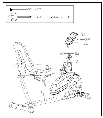
Attach the Pedals (No. 18L/R) to the Crank (No. 12) using the Spanner (No. 88).
NOTE: Make sure to attach Right Pedal (No. 18R), marked (R), to the right side of the Crank (No. 12). It should be tightened clockwise. Attach the Left Pedal (No. 18L), marked (L), to the left side of the Crank (No.12).
STEP 7
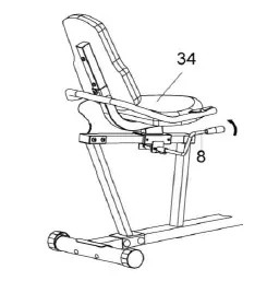
Remove the preassembled 4 Screws (No. 32) from the Meter (No. 33) using Spanner (No. 88).
Connect the Sensor Connecting Wire (No. 22) and Pulse Connecting Wire 1 (No. 23) to the relative wires of Meter (No. 33), th en lock the Meter (No. 33) to the bracket of Handlebar Post (No. 2) using 4 Screws (No. 32) that were just removed with Spanner (No. 88).
Note: To avoid damaging the wires, please push them into the Handlebar Post (No. 2) before secure the Meter (No. 33) onto the bracket.
THE ASSEMBLY IS COMPLETE!
ADJUSTMENT GUIDE
ADJUSTING THE SEAT POSITION
 To move the Seat (No. 34) forward or b ackward, while seated on the bike, put your feet on the floor. Shift the Adjustment Handle (N o. 8) down to loosen. Move the Seat (No. 34). Shift the Adjustment Handle (No. 8) up to secure.
ADJUSTING THE LEVEL
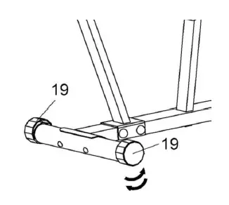 If at any point the bike does not feel level, you can adjust the Rear End Caps (No. 19).
ADJUSTING THE TENSION
Adjust the tension by rotating the Tension Controller (No. 28) clockwise to increase the level of resistance. Rotate the Tension Controller (No. 28) counter-clockwise to decrease the level of resistance.
Tension levels are set at Level 1 being the lowest and Level 8 being the highest.
MOVING THE BIKE
Lift the bike by the Rear Stabilizer (No. 11) until the wheels on the Front Stabilizer (No. 10) touch the floor. You can now move the bike to your desired location with ease.
BATTERY INSTALLATION & REPLACEMENT
BATTERY INSTALLATION
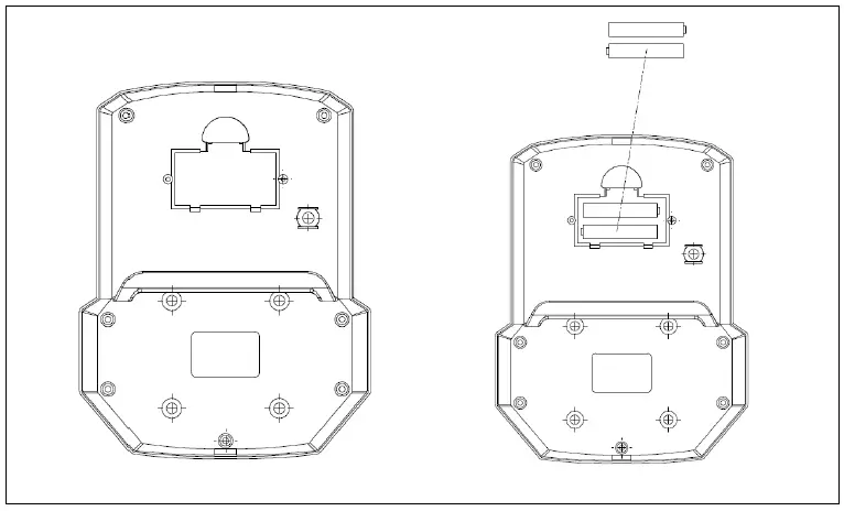
The meter uses 2 AAA 1.5V batteries. Open the battery cover from the back of meter, then put 2 batteries into the battery compartment. Make sure the (+) and (-) ends of the batteries are in the correct position. Put the battery cover back.
BATTERY REPLACEMENT
Open the battery cover, remove the old batteries, and replace with new batteries. Make sure the (+) and (-) ends of the batteries are in the correct position. Put the battery cover back. When changing batteries, always replace both with new batteries. Do not mix old and new batteries.
EXERCISE METER
FUNCTION BUTTONS: 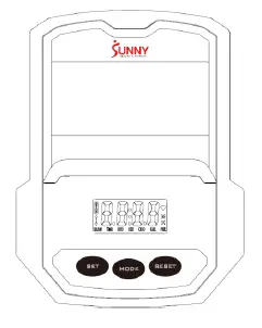
MODE: Press the button to select TIME, DISTANCE, and CALORIES to preset. Press the button for selection function display value on LCD or enter after setting. Press the button and hold for 3 seconds to reset all values except odometer to zero. (When user replaces the batteries, all the values will reset to ZERO automatically).
SET: To set up the target value of TIME, DISTANCE, and CAL. Press the button and hold for 2 seconds to speed up the increment.
RESET: Press the button to reset function value when setting. Press the button and hold for 3 seconds to reset all values except odometer to zero (When the user replaces batteries, all the values will reset to ZERO automatically).
FUNCTIONS & OPERATIONS:
- BATTERY INSTALLATION:
Please install 2 AAA 1.5V batteries in the battery case on the back of computer.(Whenever batteries are removed, all the function values will be reset to zero.) - AUTO ON/OFF:
Once the user begins to exercise, the computer will show the workout value automatically. After about 4 minutes of inactivity, the computer will turn off. Odometer value does not reset to 0 when the computer turns off. When the user starts to exercise again, the workout value of odometer will accumulate continuously. - AUTO SCAN:
After the computer is powered on, press MODE button and the LCD will display all function values from TIME-SPEED-DISTANCE-CALORIES-ODOMETER-PULSE. Each value will be held for 6 seconds. - SPEED:
Displays the current training speed from 0.0 to 99.9 MPH (Miles per hour). - DISTANCE:
Accumulates total distance from 0.0 up to 9999 M (miles). The user may preset target distance by pressing the SET & MODE buttons. Each increment is 0.1 M (Miles). Automatically counts down from targeting value during exercise. - TIME:
Accumulates total time from 00:00 up to 99:59. The user may preset target time by pressing SET & MODE buttons. Each increment is 1 minute.
Automatically counts down from targeting value during exercise. - CALORIES:
Accumulates calories burned during training from 0 to 9999 (Cal). The user may also preset the target calories before training by pressing the SET & MODE buttons. Each setting increment is 1 Cal.
Automatically counts down from targeting value during exercise.
Note: This data is a rough guide which cannot be used in medical treatment. - ODOMETER:
Displays the total accumulated distance from 0 to 9999 M (miles). User can also press MODE button to display the odometer value. - PULSE:
The computer will display the user’s heart rate in beats per minute (BPM) during training. Note: This data is a rough guide which cannot be used in medical treatment. - RESET:
Press the button and hold for 3 seconds to reset all values except odometer to zero.
NOTE:
- If the computer display is abnormal, please re-install the new batteries and try again. Always change both batteries at the same time. Do not mix battery types and do not mix old and new batteries.
- Battery Spec: 1.5V UM-4 or AAA (2PCS).
- Dispose the batteries safely, according to your state and regional guidelines.
APP CONNECTION
- Scan below QR code to enter the app store and download the Sunny Health & Fitness app to your mobile phone.
- Press the Bluetooth switch to connect. T hen you can use the app through your mobile phone.