![]() RVSC 12000 BTU DC 12V RV Air Conditioning
RVSC 12000 BTU DC 12V RV Air Conditioning
Instruction Manual
WHAT’S INSIDE THE BOX:
MABRU 12V AC
INSTALLATION ACCESSORIES KIT:
- Extension cable with in-lined 80 amps fuse
- L Bracket Positioning plates
- Return grilles
- Flexible external Gasket
- Positioning plates
- Plastic bag with nut and bolts
- Plastic bag with LED lights -cover for nuts with LED harness
- Remote wireless control (AAA batteries not included)
- Tie wraps
- Drain hoses
- Extra plastic angle for specific buses or other kind of vehicles.
- Extra positioning rubber shock absorber in case you want to add more compression resistance to the compressible gasket.
- Paper template
RECOMMENDED ADDITIONAL ITEMS FOR INSTALLATION:
Cable gland
UV rated sealant
Anti-rust paint
PARAMETERS
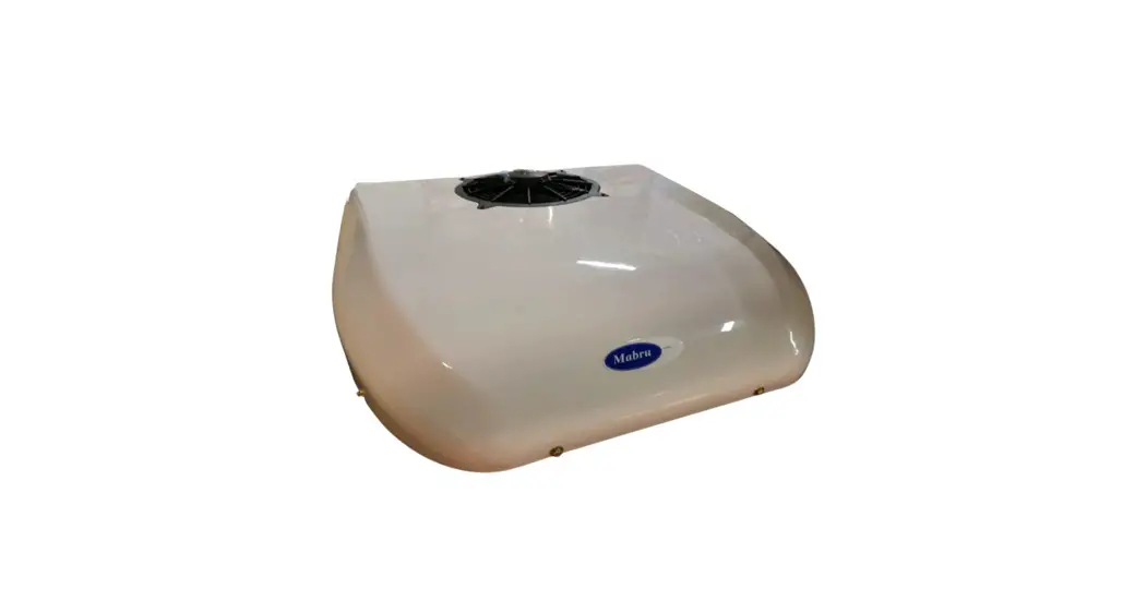
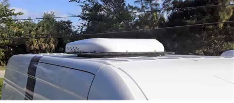
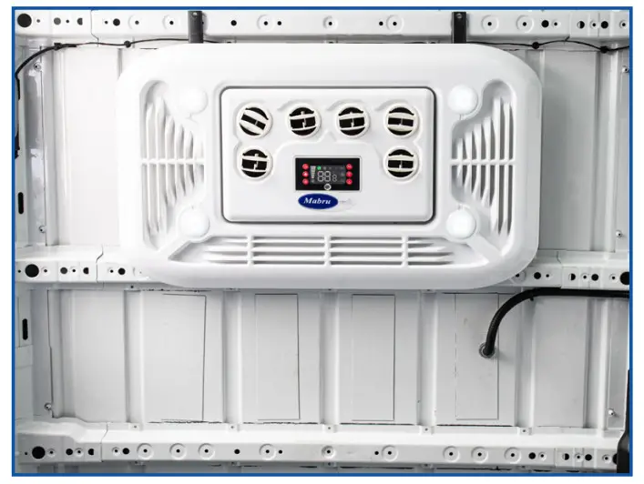
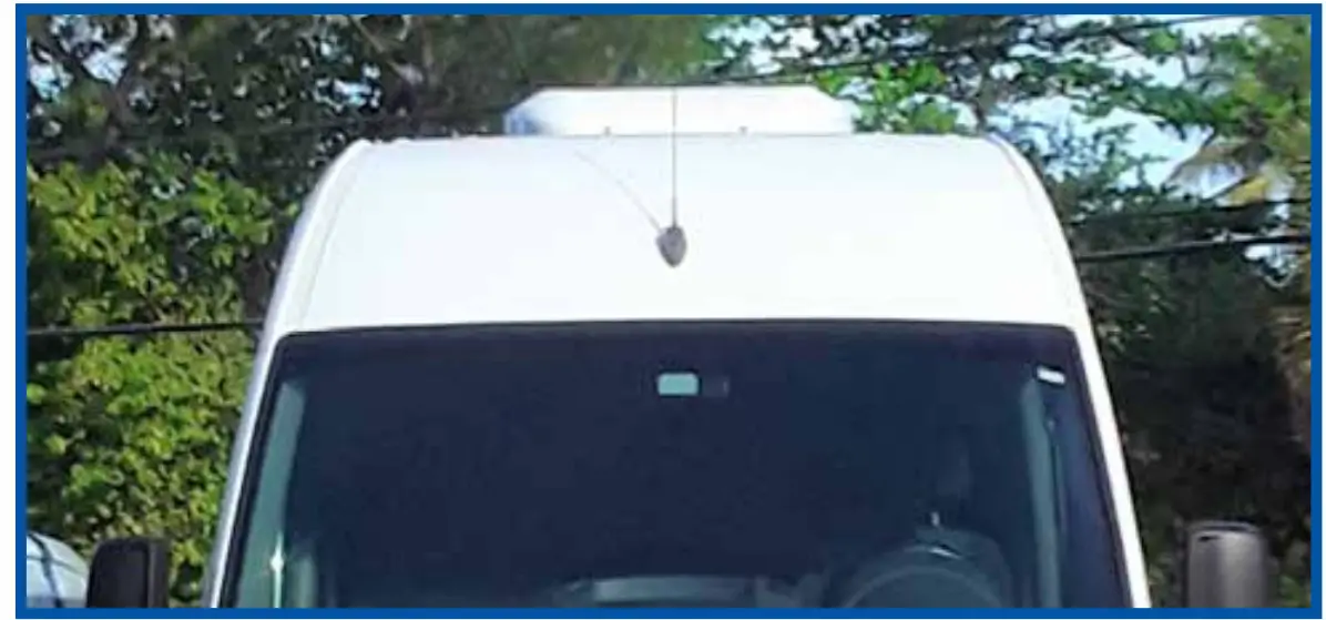
The Mabru Power Systems 12V rooftop air conditioning unit is the ideal unit for RVs, trucks, vans, buses, and motorhomes. Our unit has been designed to be low profile, efficient, and reliable.
| Rated Voltage | 12V | Size (roof) | 38.19L x 33.78W x 6.5H |
| Evaporation Air Voltage | 380 CFM | Max Size | 36.61L x 21.26W |
| BTU | 12000 | Min Size | 18.11L x 11.42W |
| Condenser Air Voltage | 3.65 CFM | Min Size Hole | 14″x14″ or 14 5/8″ x 20 1/8″ |
| Rated Wattage | 700W | Weight | 59lb |
| Refrigerant | R134 | Shipping weight | 76lb |
CURRENT CONSUMPTION AT 12V
- High speed (max 52Amp, Medium 43Amp, Low 32Amp (eco)
STANDARD INSTALLATIONS:
OPTION 1:
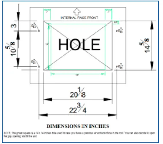
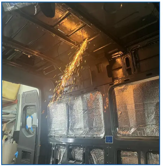
The standard procedure to install the unit is by creating a new opening using the template size: 20 1/8 Inches x 14 5/8 Inches
STEPS:
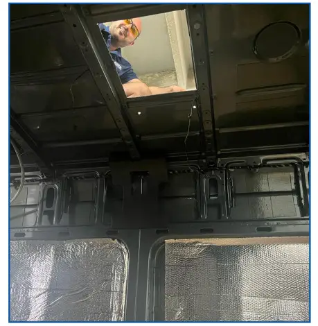
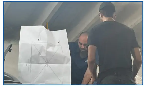
- Mark your cutout from the top of the roof.

- Drill the 4 holes for the pass-thru bolts.
(For easier fit, use a unibit drill to oversize the holes)
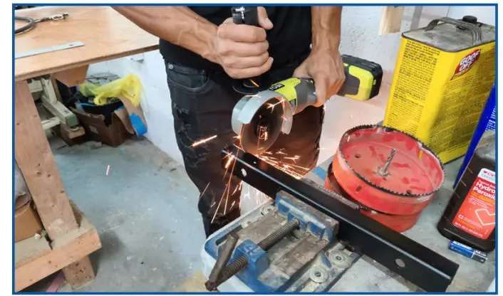
- Once the opening is cut you must smooth the edges and paint it with anti-rust paint.
- Clean the surface thoroughly of any debris, dirt and/or grease to allow the gasket seal properly.
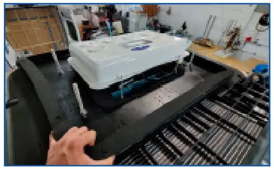
- Carefully carry the unit in the box, still facing up to have access to the black plastic Mounting plate (Outdoor and indoor unit separator)
- Peel the sticker from the foam gasket gradually while sticking it on the mounting plate, making sure it’s outside the 4 screws to prevent water leaks.
Manually shape it to square shape while positioning.
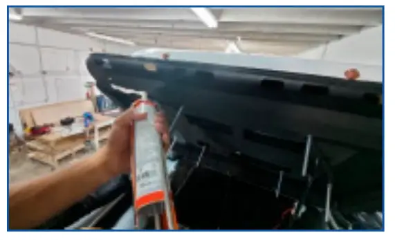
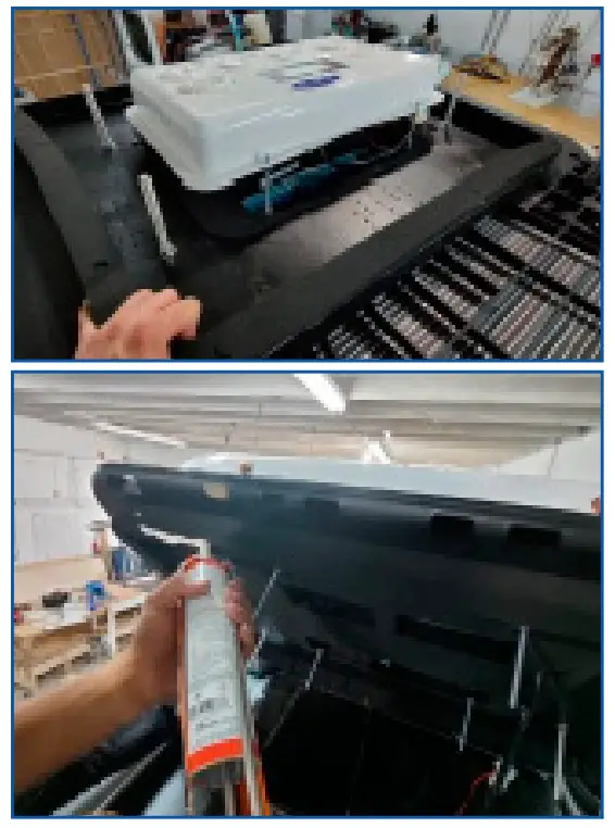
- Once the gasket is positioned, we recommend using a UV rated sealant before lifting, orient the unit facing the roof of the vehicle.

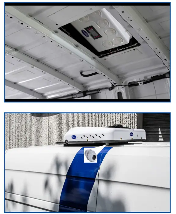
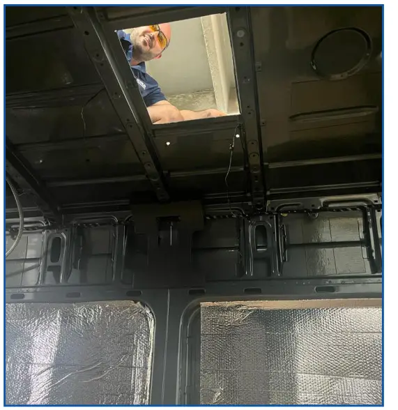
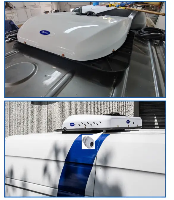
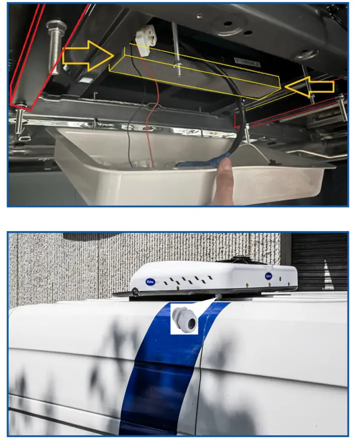
- Once the unit is sitting on top of the roof, take the wire harness and drill a hole in the selected location to pass it thru the roof, using a Cable Gland, well sealed with the same sealant used for the gasket to prevent water leaks.

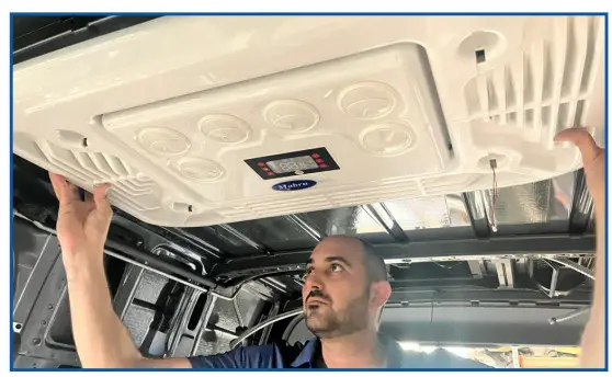
- From inside the vehicle, you will have the unit upside down and ready to tighten the mounting screws on the nuts using the L bracket positioning plates provided. If necessary, adjust the plates to distribute the stress on the roof surface. Don’t exceed more than 15Nm torque.

- Take the return grille and connect the wire harnesses to do a series wire connection for the LED lights. Once the cables are located, screw the nuts to hold and adjust panel

- Finish the installation by plugging the Led Lights and clip it on its location to cover the nuts.

- To complete your installation, connect the Mabru air conditioner to a 12V power supply house battery bank and enjoy.

CUSTOMIZED INSTALLATION INSTRUCTIONS:
OPTION 2:
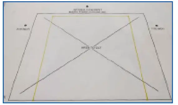
Using a pre-existing 14×14 inches opening OR creating a New 14×14 inches opening using the template provided.
STEPS:
- Place the template over the pre-existing 14×14 hole to determine screw hole placement.


- Drill the 4 holes for the pass-thru bolts. (For easier fit, use a unibit drill to oversize the holes)

- Once the opening is cut you must smooth the edges and paint it with anti-rust paint.

- Clean the surface thoroughly of any debris, dirt and/or grease to allow the gasket seal properly.
- Carefully carry the unit in the box, still facing up to have access to the black plastic Mounting plate (Outdoor and indoor unit separator)
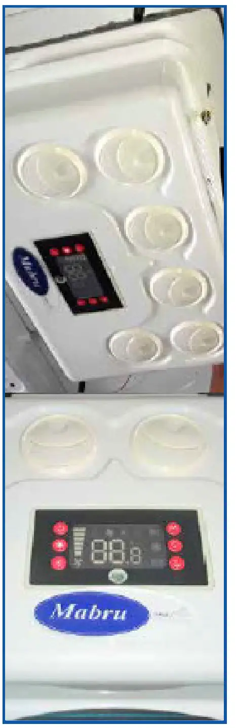
- Unscrew the white plastic vent face taking out the 4 adjustable nuts.
IMPORTANT: Make sure not to pull the wires from the back of the circuit control panel. If you are not careful, you could disconnect some of the wires and the sealed circuit board compartment will not be easily accessible.
It is highly recommended to use enough temporary tape to keep it taut while handling the face while hanging.
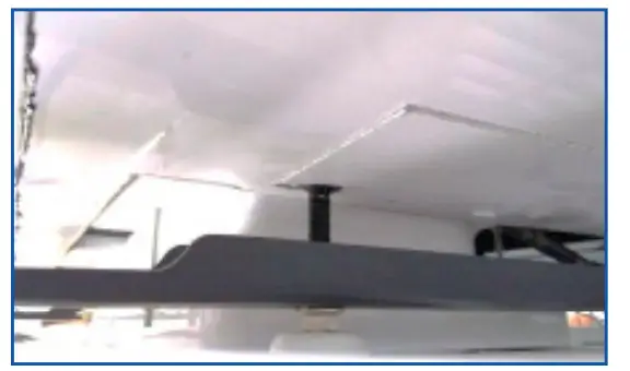
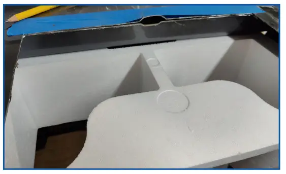
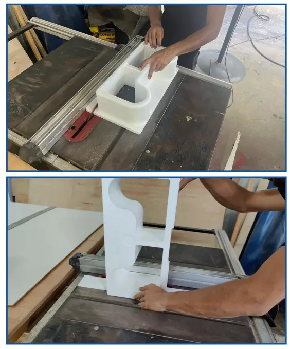
NOTE: This is not a standard installation procedure, so we recommend being careful when fitting the unit into a 14×14 hole. - Take out the remaining 2 nuts holding the Styrofoam conduit in order to pull it out and make any necessary cuts to mold it to size.

- From inside the vehicle, lay the Styrofoam on the surface and mark the cutouts in the Styrofoam duct to fit the smaller area you are trying to fit. (You may encounter some obstructions, such as roof rails.) Keep in mind that you are adding extra inches between the unit and the internal face of the unit, so the Styrofoam needs to be adjusted on its depth measures as well.

- After having the Styrofoam already molded, go back to the roof and peel the sticker from the foam gasket gradually while sticking it on the mounting plate, making sure its outside the 4 screws to prevent water leaks. Manually shape it to a square shape while positioning.

- Once the gasket is positioned, we recommend using a UV rated sealant before lifting, orient the unit facing the roof of the vehicle.

- Once the unit is sitting on top of the roof, take the wire harness and drill a hole in the selected location to pass it thru the roof,using a Cable Gland, well-sealed with the same sealant used for the gasket to prevent water leaks.

- From inside the vehicle, you will have the unit upside down and ready to tighten the Fixing screws on the nuts using the locating plates provided. If necessary,adjust the plates to distribute the stress on the roof surface Don’t exceed more than 15Nm torque.

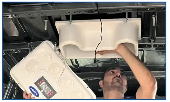
- Now it’s time to position the Styrofoam from the inside. Due to the Non-Standard unit adjustment, it will be necessary to fill the separation between the unit and the Styrofoam ventilation duct. By using insulation material, such as high-density foam, foam gasket material or similar, fill in the empty (missing) space maintaining the separation between the discharge duct and the return duct. If this step is not followed, the machine will read an erroneous temperature by allowing cold air to pass directly to the return temperature sensor and this will cause the unit to perform very frequent recess cycles, causing the equipment to malfunction.

- Take the return grille and connect the wire harnesses to do a series wire connection for the LED lights. Once the cables are located, screw the nuts to hold and adjust pane
- Finish the installation by plugging the Led Lights and clip it on its location to cover the nuts.
- Connect the Mabru air conditioner to a 12V power supply house battery bank and enjoy.
TROUBLESHOOTING…ERROR CODES
| DIGITAL DISPLAY | FAULT DESCRIPTION | FAULT DESCRIPTION |
| E2 | Outside Fan Failure Condenser Air Restriction High Pressure | Check to see if pressure is too high and if the fan is running |
| E3 | Battery wires not adequate for this unit | High Pressure |
| E4/LU | Undervoltage protection | Low battery |
| E6 | Condensing coil fan failure or air circulation | Short circuit of motor poor contact of plug |
| E7 | Compressor malfunction | Compressor terminals failure, compressor short |
| E9/PER | Pressure switch protection | Pressure switch Failure |
| OPE | Bad temperature sensor, open circuit | Check plug is disconnected or wire is broken/damaged |
| SHr | Temperature sensor, short circuit | Replacement of temperature sensor |
| AC | Cooling failure | Low refrigerant |
| CS | Defrost | Defrost necessary |
TROUBLESHOOTING
NOTES
To clear the fault turn the power o° for 5 seconds.
LOW VOLTAGE FAULT AND UNDERVOLTAGE VALUE ADJUSTMENT
The undervoltage value can be adjusted between the range of 9-28 volts. When the battery voltage is lower than the under voltage protection values the system will stop working and the error code LU will be displayed on the main display.
STEPS TO ADJUST UNDER VOLTAGE PROTECTION VALUES
- Power on unit.
- Press and hold powerbutton for 6 sec.
- Press temperature button up or down.
- To save the settings press the power button and the system will exit the undervoltage adjustment mode.
WARRANTY
Mabru Power Systems offers a one year limited warranty. If the product is installed as original equipment on a vehicle, the warranty period shall begin on the date of the original purchase of the vehicle. In all other instances, the warranty shall begin on the date of the products purchase. The Consumer must establish these dates by presenting legible papers at the time the warranty claim is made showing the applicable purchase date Any defective parts will be repaired. All replacements and exchanges will be made using new, remanufactured or refurbished parts or components at the option of Mabru Power Systems. This warranty does not cover damage caused by mishandling, neglect, lightning, corrosive atmosphere, improper installation,improper application or improper energy supply. This warranty does not cover damages or equipment failure caused by the use of non Mabru Power Systems parts or components.
For full warranty information visit our website. To file a claim call or send an email to [email protected]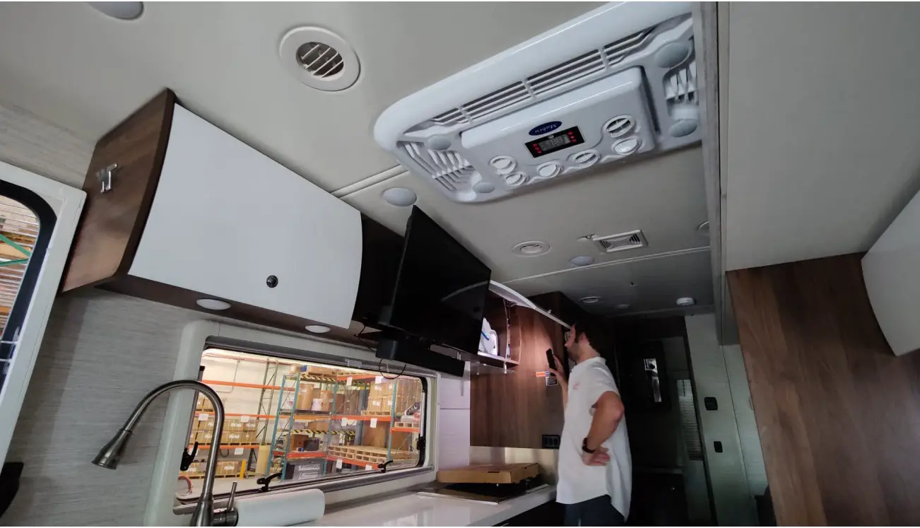
RV AIR CONDITIONING
Mabru Rooftop Installation Manual
1-888-818-2814
www.MabruStore.com
[email protected]


