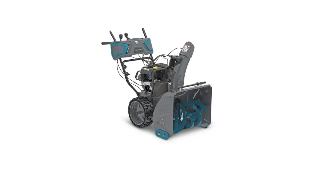
![]() 13144 Snowblower Champion Power Equipment
13144 Snowblower Champion Power Equipment
User Manual
06013144 Snowblower Champion Power Equipment
model number 060-1314-4
contact us: 1.866.523.5218
IMPORTANT: Please read this manual carefully before operating this snowblower and save it for reference.![]() WARNING: Machine is without engine oil. Properly fill engine oil prior to use to prevent engine damage.
WARNING: Machine is without engine oil. Properly fill engine oil prior to use to prevent engine damage.![]() For problems or questions, DO NOT ReTURN TO STORe.
For problems or questions, DO NOT ReTURN TO STORe.
Please contact one of our Customer Service Agents
who would be happy to assist you.
For Customer Assistance Please Call:![]() 1.866.523.5218
1.866.523.5218
SAFETY INSTRUCTIONS
SAFETY DEFINITIONS
The purpose of safety symbols is to attract your attention to possible dangers. The safety symbols, and their explanations, deserve your careful attention and understanding. The safety warnings do not by themselves eliminate any danger. The instructions or warnings they give are not substitutes for proper accident prevention measures.![]() DANGER indicates a hazardous situation which, if not avoided, will result in death or serious injury.
DANGER indicates a hazardous situation which, if not avoided, will result in death or serious injury.![]() WARNING indicates a hazardous situation which, if not avoided, could result in death or serious injury.
WARNING indicates a hazardous situation which, if not avoided, could result in death or serious injury.![]() CAUTION indicates a hazardous situation which, if not avoided, could result in minor or moderate injury.
CAUTION indicates a hazardous situation which, if not avoided, could result in minor or moderate injury.![]() NOTICE indicates information considered important, but not hazard-related (e.g., messages relating to property damage).
NOTICE indicates information considered important, but not hazard-related (e.g., messages relating to property damage).
GENERAL SAFTEY
– Read the operating and service instruction manual carefully. Be thoroughly familiar with the controls and the proper use of the equipment. Know how to stop the unit and disengage the controls quickly.
– Never allow children under 16 years old to operate the equipment. Never allow adults to operate the equipment without proper instruction.
– Thrown objects can cause serious injury. Keep the area of operation clear of all persons, particularly small children, and pets. Plan your snow discharge pattern to prevent throwing material toward cars, structures, roads and people.
– Exercise caution to avoid slipping or falling, especially when operating in reverse.
– Keep in mind that the operator or user is responsible for accidents or hazards occurring to other people or their property.
– Never use the snowblower under the influence of alcohol, medication, or recreational drugs, or if you are tired or ill.
PREPARATION FOR USE
– Thoroughly inspect the area where the equipment is to be used and remove all doormats, sleds, boards, wires, and other foreign objects.
– Disengage all clutch handles before starting the motor.
– Do not operate the equipment without wearing adequate winter garments. Wear footwear which will improve footing on slippery surfaces.
– Adjust the auger housing height to clear gravel or crushed rock surface.
– Never attempt to make any adjustments while the engine is running (except where specifically recommended in the manual).
– Let engine and machine adjust to outdoor temperatures before starting to clear snow.
– The operation of any powered machine can result in foreign objects being thrown into the eyes. Always wear safety glasses or eye shields during operation, or while performing an adjustment or repair.
– Inspect the auger and impeller before starting to ensure that there is no ice build up.
SAFE HANDLING OF GASOLNE
To avoid severe injury or property damage use high levels of care while handling gasoline. Gasoline is an extremely flammable substance and the vapours are explosive. Serious personal injury can occur when gasoline is spilled on yourself or your clothes, which can ignite. If you come into contact with gasoline, wash affected areas of skin and change clothing immediately.
– Use only an approved gasoline container.
– Extinguish all cigarettes, cigars, pipes and other sources of ignition prior to working with or near gasoline.
– Never refuel machine within closed spaces.
– Never remove gas cap or add fuel while the engine is hot or running.
– Allow engine to cool at least two minutes before refueling.
– Do not over fill fuel tank. Keep fuel level at least ½” (1.27 cm) below bottom of filler neck to provide space for fuel expansion.
– Replace gasoline cap and tighten securely.
– If gasoline is spilled, wipe it off the engine and equipment. Move machine to another area. Wait 5 minutes before starting the engine.
– Never store the machine or fuel container inside where there is an open flame, spark or pilot light (e.g., furnace, water heater, space heater, clothes dryer etc.).
– Allow machine to cool at least 5 minutes before storing.
– Never fill containers inside a vehicle or on a truck or trailer bed with a plastic liner. Always place containers on the ground away from your vehicle before filling.
– If possible, remove gas-powered equipment from the truck or trailer and refuel it on the ground. If this is not possible, then refuel such equipment on a trailer with a portable container, rather than from a gasoline dispenser nozzle.
– Keep the nozzle in contact with the rim of the fuel tank or container opening at all times until fueling is complete. Do not use gas cans with nozzle lockopen devices.
OPERATION
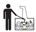
– Do not put hands or feet near or under rotating parts. Keep clear of the discharge opening at all times.
– Exercise extreme caution when operating on or crossing gravel drives, walks, or roads. Stay alert for hidden hazards or traffic.
– After striking a foreign object, stop the engine, remove the spark plug, thoroughly inspect the snowblower for any damage, and repair the damage before restarting and operating the snowblower.
– If the unit should start to vibrate abnormally, stop the engine and check immediately for the cause. Vibration is generally a warning of trouble. Vibration typically indicates a mechanical problem has occurred.
– Stop the engine whenever you leave the operating position, before unclogging the auger housing or discharge guide, and when making any repairs, adjustments, or inspections.
– Before cleaning, inspecting or repairing any parts of the snowblower, ensure the auger has stopped moving. Disconnect the spark plug wire and keep it away from the plug to prevent accidental starting.
– Before leaving the machine unattended, disengage all control levers, stop the engine and remove the safety key.
– Do not run the engine indoors. Exhaust fumes are dangerous.
– Do not clear snow across the face of slopes. Exercise extreme caution when changing direction on slopes. Do not attempt to clear steep slopes.
– Never operate the snowblower without proper guards, plates or other safety protective devices in place.
– Never operate the snowblower near glass enclosures, automobiles, window wells, etc., without proper adjustment of the snow discharge angle. Keep children and pets away. – Do not overload the machine capacity by attempting to clear snow at too fast a rate.
– Never operate the machine at high transport speeds on slippery surfaces. Use care when reversing.
– Never direct discharge at bystanders or allow anyone in front of the unit.
– Disengage power to the impeller when snowblower is transported or not in use.
– Use only attachments and accessories approved by the manufacturer of snowblower.
– Never operate the snowblower without good visibility or light. Always be sure of your footing, and keep a firm hold on the handles. Walk; never run.
– Take all possible precautions when leaving the machine unattended. Disconnect the power take-off and stop the engine.
– Keep all nuts, bolts and screws tight to be sure the equipment is in safe working condition.
– Replace worn or damaged parts for safety. Use only genuine replacement parts and accessories.
– This snowblower is not intended for use by persons (including children) with reduced physical, sensory or mental capabilities, or lack of experience and knowledge, unless they have been given supervision or instruction concerning use of the appliance by a person responsible for their safety.
– Be careful while working on the machine or clearing a blockage in the auger or impeller to ensure that fingers and hands do not become crushed or cut.
– Do not touch hot engine components like the muffler, muffler guard or engine block during operation of the snowblower as they will cause burns.
– Should the unit stop discharging snow for any reason, release the controls to stop and inspect for any lodged items or damaged parts in the auger housing.
CLEARING A CLOGGED DISCHARGE CHUTE
Hand contact with the rotating impeller inside the discharge chute is the most common cause of injury associated with snowblowers. Never use your hand to clean out the discharge chute or auger assembly.
To clear the chute:
– SHUT THE ENGINE OFF!
– Wait 10 seconds to be sure the impeller blades have stopped rotating.
– Always use a clean-out tool. DO NOT use your hands.
MAINTENANCE AND STORAGE
– Check shear bolts, engine mounted bolts, etc., at frequent intervals for proper tightness to sure the equipment is in safe, working condition.
– Never store the machine with fuel in the fuel tank inside a building where ignition sources are present such as hot water heaters, space heaters, clothes dryers or any open flame sources. Allow the engine to cool before storing in any enclosure.
– Always refer to owner’s guide instructions for important details if the snowblower is to be stored for an extended period.
– Maintain or replace safety and instructions labels, as necessary.
– Run the snowblower for one minute to clear out packed snow and ice to prevent freeze-up during storage.
SAFETY SYMBOLS
Some of the following symbols may be used on this product. Please study them and learn their meaning. Proper interpretation of these symbols will allow you to more safely operate the product.
| Symbol | Meaning |
 | Read Operator’s Manual. To reduce the risk of injury, user must read and understand operator’s manual before using this product. |
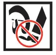
| eye and ear Protection. Always wear safety goggles or safety glasses with side shields, and as necessary a full face-shield as well as full ear protection when operating this product. | |
 | Safety Alert. Precautions that involve your safety. |
 | Risk of fire/explosion. Fuel and its vapours are extremely flammable and explosive. Fire can cause severe burns or death. Do not add fuel while the product is operating or still hot. Open flame Alert. Fuel and its vapours are extremely flammable and explosive. Keep fuel away from smoking, open flames, sparks, pilot lights, heat, and other ignition sources. |
 | electric Shock. Failure to use the starter in dry conditions and to observe safe practices can result in electric shock. |
 | Toxic fumes. The engine exhaust from this product contains chemicals known to cause cancer and birth defects and other reproductive harm. Risk of Asphyxiation. This engine emits carbon monoxide, an odourless, colourless poison gas. Breathing carbon monoxide can cause nausea, fainting or death. Use only in a well-ventilated area. |
| Symbol | Meaning |
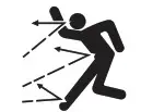 | Thrown Objects. This machine may pick up and throw objects which can cause serious personal injury. |
 | Always Use Chute Tool. Never use your hands to clear a clogged chute assembly. Shut OFF engine and remain behind handles until all moving parts have stopped before unclogging. |
 | Hot Surface. To reduce the risk of injury or damage, avoid contact with any hot surface. |
 | Risk of Fire. Fuel and its vapours are extremely flammable and explosive. Fire can cause severe burns or death. Do not add fuel while the product is operating or still hot. |
 | Rotating Auger. DANGER: Avoid injury from rotating auger keep feet away. |
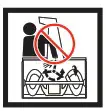 | Rotating Blades. Never put your hand in the chute. Contact with rotating parts can amputate fingers and hands. |
Some of the following symbols may be used on this product. Please study them and learn their meaning. Proper interpretation of these symbols will allow you to more safely operate the product.
Operation Symbols
Symbol | Meaning |
 | Check Oil Level. Recommended oil is OW-30. The engine can be seriously damaged without oil. Always check the oil level before using. The machine must be resting firmly on level ground when checking. |
 | Check Fuel Level. Use clean, fresh, regular unleaded gasoline with a minimum octane rating of 87 and an ethanol content of less than 10% by volume. |
 | Minimum Octane. Use clean, fresh, regular unleaded gasoline with a minimum octane rating of 87 and an ethanol content of less than 10% by volume. |
 | Valve: ON. Move the fuel valve lever to the on position. |
 | Choke: ON. To start a cold engine, move the choke lever to the choke position. |
 | Throttle: Full Speed. Move the throttle lever to full speed to start the engine. |
| Low Speed. Lowers the speed of the engine. | |
 | Engine Key. Make sure the engine safety key is inserted into the key hole. |
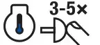 | Cold Prime. To start a cold engine, prime 3-5 times. |
| Symbol | Meaning |
 | Warm Prime. To start a warm engine, DO NOT prime. |
 | Recoil Start. Pull the recoil starter grip to start manually. |
 | Choke: Off. When the engine starts, move the choke to run position. |
 | fuel Valve: Off. Move the fuel valve lever to the OFF position. |
 | Remove engine Key. Remove the engine key. |
 | engine Start. To use the electric start feature, see this Operator’s manual for further instructions. |
 | engine Stop. |
 | Gasoline Tank: full |
 | Gasoline Tank: empty |
SPECIFICATIONS
SNOWBLOWER
| Stages | 2 |
| Speed Control | 6 forward/2 reverse |
| Clearing Width | 24″ (61 cm) |
| Clearing Depth | 23″ (58.4 cm) |
| Impeller Diameter | 12″ (30.5 cm) |
| Wheel Diameter | 15″ (38 cm) |
| Auger Diameter | 14″ (35.6 cm) |
ENGINE
| brand | Champion Power Equipment |
| Displacement | 224 cc |
| engine Model | R225S |
| Start Type | Electric, Recoil |
OIL
| Oil Capacity | 16.9 fl. oz. (0.5 L) |
| Oil Type | 0W-30 |
FUEL
Use clean, fresh, regular unleaded gasoline with a minimum octane rating of 87 and an enthanol content of less than 10% by volume.
Fuel Capacity : 0.7 gal. (2.6 L)
SPARK PLUGS
| OeM Spark Plug | F6RTC |
| Replacement Spark Plug | NGK BPR6ES or equivalent |
| Make certain the spark plug gap is 0.028 | 0.031″ (0.7 – 0.8 mm). |
BELTS
| OeM Auger belt | Gates 5LXA935E (L × W × H = 935 × 16.6 × 8.2) |
| OeM Drive belt | Megadyne HTD 840-5M15 (L × W = 840 × 15 / Pitch = 5 mm) |
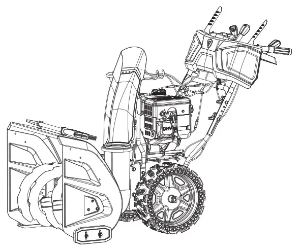
SNOWBLOWER
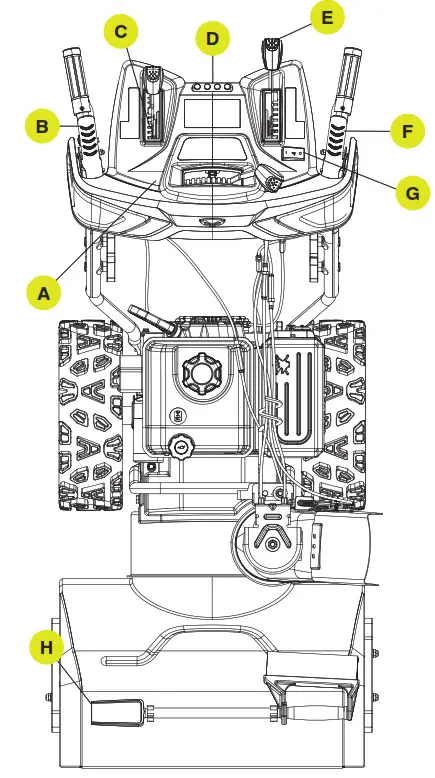 | 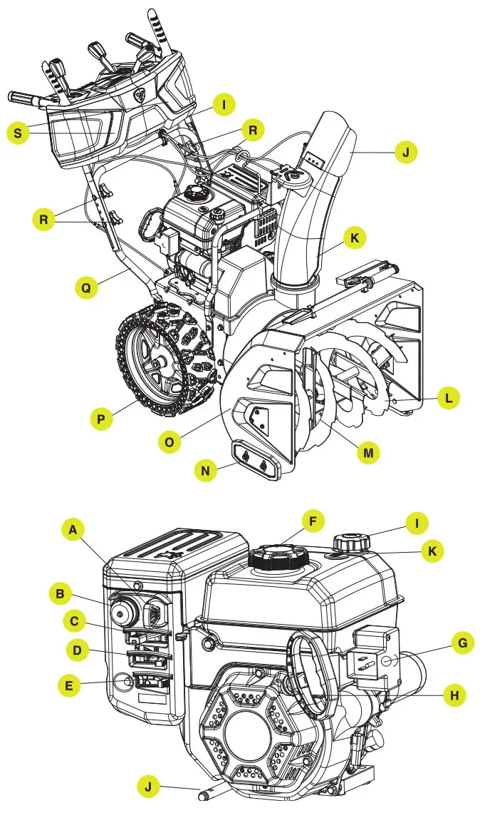 |
| A. Discharge Chute Rotation Lever B. Auger Control Lever C. Speed Control Lever D. Shear Pin Storage E. Discharge Chute Deflector Lever F. Self-drive Control Lever G. Grip Heat Warmer Switch H. Clean-out Tool and Brush I. Upper Handle J. Discharge Chute Deflector | K. Discharge Chute L. Auger M. Shave Plate N. Skid Shoes O. Auger Housing P. Wheels Q. Lower Handle R. Handle Locking Knobs S. Lights |
ENGINE
| A. Key (Safety Lock Out) B. Primer Bulb C. Throttle Lever D. Choke Lever E. Fuel Valve (On/Off) F. Fuel Cap | G. Electric Start Button H. Recoil Starter Grip I. Oil Fill and Level Check Cap J. Oil Drain Plug K. Fuel Level Gauge |
ASSEMBlY
UNPACKING
- Set the shipping carton on a solid, flat surface.
- Remove everything loose from the carton.
- Cut down the bottom carton to allow a flat surface area to install the assembly parts without scratching parts or cutting tires.
- Now you are ready for assembly.
TOOlS REQUIRED
| Part | Size |
| Wrench (included) | 13,16 |
ADDITIONAl PARTS
| Part | Part Qty. | Usage |
| Shear Pins | 4 | Spare part (preassembled) |
| Clip (for auger) | 4 | Spare part (preassembled) |
| Starter Electric Cord | 1 | Accessory |
| Engine Oil | 1 |
ASSEMBLY PARTS
| Part | Part Qty. | Description | Hardware Qty. | Hardware Reference | Tool(s) Needed |
| Discharge Chute | 1 | M10 Hexagon Lock Nut | 1 |  | 16 mm wrench |
| Large Washer | 1 | 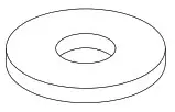 | N/A | ||
| Support Rod | 1 | 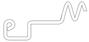 | N/A | ||
| Lower Handle | 1 | M8 x 16 Self-tapping Bolt | 4 | 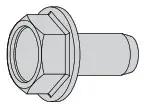 | 13 mm wrench |
| Cord Clamp (preassembled) | 1 | 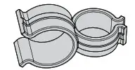 | N/A | ||
| Upper Handle | M8 x 50 Half Round Bolt | 4 | 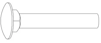 | N/A | |
| Curved Washer | 4 | 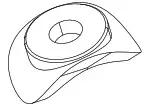 | N/A | ||
| Rotating Knob | 4 | 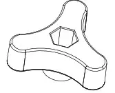 | N/A | ||
| Cable Tie | 3 | 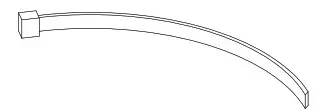 | N/A |
HANDLE
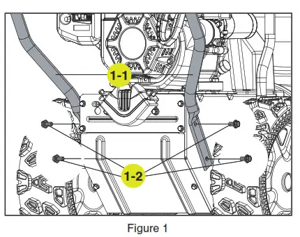
- Attach the lower handle (1-1) onto the unit body with 4 self-tapping bolts (1-2) using included tool or your own 13mm wrench (Fig. 1).

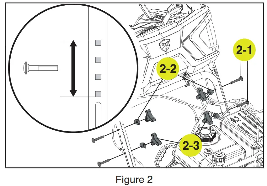
- Connect the upper and lower handle with bolts (2-1), washers (2-2) and locking knobs (2-3) (Fig. 2). The top handle can adjust to 4 positions. You can come back later and adjust to a more comfortable height.

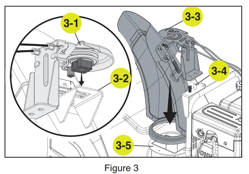
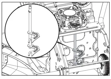
- Remove the chute pivot assembly (3-1) from the bubble wrap and attach to the bracket on the chute (3-2). Align the round and square connector on the underside of the chute pivot assembly to the bracket. The square connector snaps in place. Then, place the entire chute (3-3) over the two posts (3-4) aligning the chute with the base (3 5). The chute will just rest on the base and rotate at this point (Fig. 3).
 NOTICE: Make sure the chute pivot assembly snaps securely into thechute bracket as shown in Step 3.
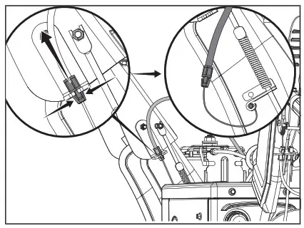
 - Put the snow discharge chute cable wire form on the snow discharge support using the washer (4-1) and nut (4-2). Securely tighten the assembly (Fig. 4) using included tool or your own 16mm wrench. This will be the guide that channels all the cables over the engine from the chute area.

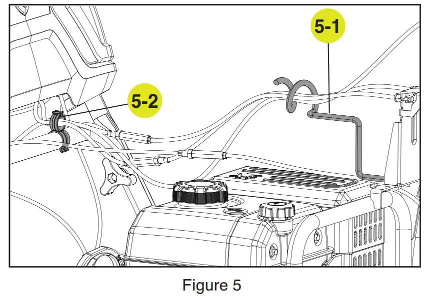
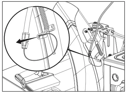
- Route the cables through the support rod wire form (5-1) and cord clamp (5-2) on the lower handle. Additional cable ties are included to neaten up the cables. Keep loose before first use and adjust. When comfortable all the cabling is in proper position, tighten up the cable ties (Fig. 5).

 NOTICE: Make sure the chute pivot assembly snaps securely into thechute bracket as shown in Step 3.
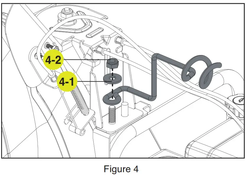
CHECK/ADD ENGINE OIL
Capacity of engine oil: 16.9 fl. oz. (0.5 L)
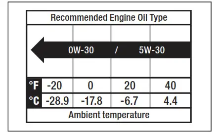
Use 0W-30, but in some cases, depending on weather, 5W-30 will work. See chart for oil type recommendations.
Weather will affect engine oil and engine performance. Change the type of engine oil used based on weather conditions to suit the engine needs.
Synthetic oil may be used after the 5-hour initial break-in period. Using synthetic oil does not increase the recommended oil change interval.
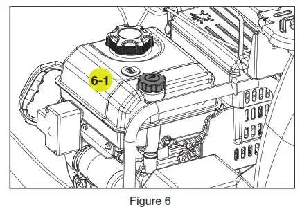
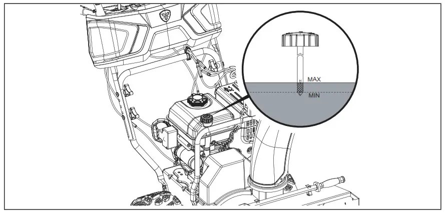
- Check the oil with engine stopped and level.
- Remove the oil cap/dipstick (6-1) and wipe it clean (Fig. 6).

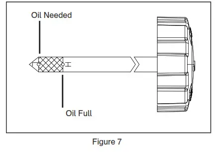
- Insert the oil cap/dipstick into the oil filler neck but do not screw it in, then remove it to check the oil level. Oil Full
- If the oil level is near or below the lower limit mark on the dipstick, remove the oil cap/dipstick, and fill with the recommended oil to the upper limit mark. Do not overfill (Fig. 7).

- Reinstall the oil cap/dipstick
![]() WARNING: Machine is shipped without engine oil, properly fill engine oil prior to use to prevent engine damage.
WARNING: Machine is shipped without engine oil, properly fill engine oil prior to use to prevent engine damage.
ADD FUEL
Fuel tank capacity: 0.7 gal. (2.6 L)
Use clean, fresh, regular unleaded gasoline with a minimum octane rating of 87 and an ethanol content of less than 10% by volume.
SAFE HANDLING OF GASOLINE
To avoid severe injury or property damage use high levels of care while handling gasoline.
Gasoline is an extremely flammable substance and the vapours are explosive. Serious personal injury can occur when gasoline is spilled on yourself or your clothes, which can
ignite. If you come into contact with gasoline, wash affected areas of skin and change clothing immediately.
- Use only an approved gasoline container.
- Extinguish all cigarettes, cigars, pipes and other sources of ignition prior to working with or near gasoline.
- Never refuel machine within closed spaces.
- Never remove gas cap or add fuel while the engine is hot or running.
- Allow engine to cool at least two minutes before refueling.
- Do not over fill fuel tank. Keep fuel level at least ½” (1.27 cm) below bottom of filler neck to provide space for fuel expansion.
- Replace gasoline cap and tighten securely.
- If gasoline is spilled, wipe it off the engine and equipment. Move machine to another area. Wait 5 minutes before starting the engine.
- Never store the machine or fuel container inside where there is an open flame, spark or pilot light (e.g., furnace, water heater, space heater, clothes dryer etc.).
- Allow machine to cool at least 5 minutes before storing.
- Never fill containers inside a vehicle or on a truck or trailer bed with a plastic liner. Always place containers on the ground away from your vehicle before filling.
 WARNING: Gasoline is highly flammable and explosive, and you can be burned or seriously injured when refueling.
– Stop engine and keep heat, sparks, and flame away.
– Refuel only outdoors.
– Gasoline is poisonous, be careful not to touch or breathe in the vapour. - If possible, remove gas-powered equipment from the truck or trailer and refuel it on theground. If this is not possible, then refuel such equipment on a trailer with a portable container, rather than from a gasoline dispenser nozzle.
- Keep the nozzle in contact with the rim of the fuel tank or container opening at all times until fueling is complete. Do not use gas cans with nozzle lock-open devices.
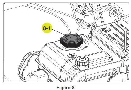
- Remove the fuel tank cap (8-1) (Fig. 8).
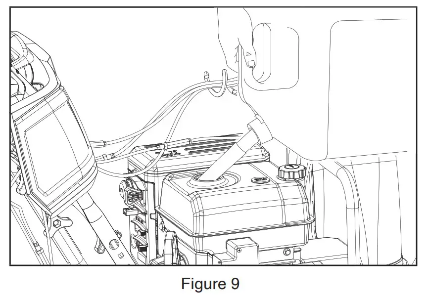
- Add fuel to the bottom of the fuel level limit in the neck of the fuel tank.B Do not overfill. Wipe up spilled fuel before starting the snowblower (Fig. 9).

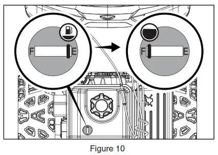
- The approximate fuel level is shown on the fuel gauge on top of the fuel tank. (Fig. 10).

OPERATION
GENERAL SAFETY
- Read the operating and service instruction manual carefully. Be thoroughly familiar with the controls and the proper use of the equipment. Know how to stop the unit and disengage the controls quickly.
- Never allow children under 16 years old to operate the equipment. Never allow adults to operate the equipment without proper instruction.
- Thrown objects can cause serious injury. Keep the area of operation clear of all persons, particularly small children, and pets. Plan your snow discharge pattern to prevent throwing material toward cars, structures, roads and people.
- Exercise caution to avoid slipping or falling, especially when operating in reverse.
- Keep in mind that the operator or user is responsible for accidents or hazards occurring to other people or their property.
- Never use the snowblower under the influence of alcohol or medication, or if you are tired or ill.
PREPARATION FOR USE
- Thoroughly inspect the area where the equipment is to be used and remove all doormats, sleds, boards, wires, and other foreign objects.
- Disengage all clutch handles before starting the motor.
- Do not operate the equipment without wearing adequate winter garments. Wear footwear which will improve footing on slippery surfaces.
- Adjust the auger housing height to clear gravel or crushed rock surface.
- Never attempt to make any adjustments while the engine is running (except where specifically recommended in the manual).
- Let engine and machine adjust to outdoor temperatures before starting to clear snow.
- The operation of any powered machine can result in foreign objects being thrown into the eyes. Always wear safety glasses or eye shields during operation, or while performing an adjustment or repair.
- Inspect the auger and impeller before starting to ensure that there is no ice buildup. operation
OPERATION
- Do not put hands or feet near or under rotating parts. Keep clear of the discharge opening at all times.
- Exercise extreme caution when operating on or crossing gravel drives, walks, or roads. Stay alert for hidden hazards or traffic.
- After striking a foreign object, stop the engine, remove the spark plug, thoroughly inspect the snowblower for any damage, and repair the damage before restarting and operating the snowblower.
- If the unit should start to vibrate abnormally, stop the engine and check immediately for the cause. Vibration is generally a warning of trouble. Vibration typically indicates a mechanical problem has occurred.
- Stop the engine whenever you leave the operating position, before unclogging the auger housing or discharge guide, and when making any repairs, adjustments, or inspections.
- Before cleaning, inspecting or repairing any parts of the snowblower ensure the auger has stopped moving. Disconnect the spark plug wire and keep it away from the plug to prevent accidental starting.
- Before leaving the machine unattended, disengage all control levers, stop the engine and remove the safety key.
- Do not run the engine indoors. Exhaust fumes are dangerous.
- Do not clear snow across the face of slopes. Exercise extreme caution when changing direction on slopes. Do not attempt to clear steep slopes.
- Never operate the snowblower without proper guards, plates or other safety protective devices in place.
- Never operate the snowblower near glass enclosures, automobiles, window wells, etc., without proper adjustment of the snow discharge angle. Keep children and pets away.
- Do not overload the machine capacity by attempting to clear snow at too fast a rate.
- Never operate the machine at high transport speeds on slippery surfaces. Use care when reversing.
- Never direct discharge at bystanders or allow anyone in front of the unit.
- Disengage power to the impeller when snowblower is transported or not in use.
- Use only attachments and accessories approved by the manufacturer of snowblower.
- Never operate the snowblower without good visibility or light. Always be sure of your footing, and keep a firm hold on the handles. Walk; never run. operation
- Take all possible precautions when leaving the machine unattended. Stop the engine and remove the safety key.
- Keep all nuts, bolts and screws tight to be sure the equipment is in safe working condition.
- Replace worn or damaged parts for safety. Use only genuine replacement parts and accessories.
- This snowblower is not intended for use by persons (including children) with reduced physical, sensory or mental capabilities, or lack of experience and knowledge, unless they have been given supervision or instruction concerning use of the appliance by a person responsible for their safety.
- Be careful while working on the machine or clearing a blockage in the auger or impeller to ensure that fingers and hands do not become crushed or cut.
- Do not touch hot engine components like the muffler, muffler guard or engine block during operation of the snowblower as they will cause burns.
- Should the unit stop discharging snow for any reason, release the controls to stop and inspect for any lodged items or damaged parts in the auger housing.
CLEARING A CLOGGED DISCHARGE CHUTE
Hand contact with the rotating impeller inside the discharge chute is the most common cause of injury associated with snowblowers. Never use your hand to clean out the discharge chute or auger assembly.
To clear the chute:
- SHUT THE ENGINE OFF!
- Wait 10 seconds to be sure the impeller blades have stopped rotating.
- Always use a clean-out tool. DO NOT use your hands.
BEFORE OPERATION
CHECK THE GENERAL CONDITION:
– Look around and underneath the engine for signs of oil or gasoline leaks.
– Remove any excessive dirt or debris, especially around the muffler and recoil starter.
– Look for signs of damage.
– Check that all shields and covers are in place, and all nuts, bolts, and screws are tightened.
CHECK THE ENGINE:
- There is no fuel or oil in the engine. Fill with fuel and add 0W-30 prior to first use.
- Check the fuel level (see ADD FUEL section).
- Check the oil level (see CHECK/ADD OIL section).
NOTICE: The engine can be seriously damaged without oil. Always check the oil level before using. The machine must stand on level ground when checking. Engine key may be attached to the recoil starter grip. Please remove the key from the recoil starter grip and attach/install properly.![]() WARNING: Never start the engine until all the above measures under assembly have been carried out.
WARNING: Never start the engine until all the above measures under assembly have been carried out.
– Never use the snowblower without first reading and understanding the instructions and all the warning and instruction stickers on the machine.
– Always use protective goggles or a visor during use, maintenance and service.
STARTING THE ENGINE
- Make sure the engine key (safety lock out) is inserted into the keyhole.

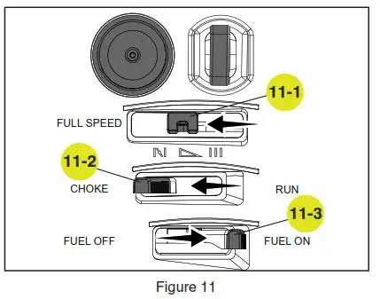
- To start a cold engine: (Fig. 11).
2a. Move the throttle lever (11-1) to full speed.
2b. Move the choke lever (11-2) to the choke position.
2c. Move the fuel shut-off lever (11-3) to the ON position.
2d. Prime 3-5 times.
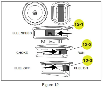
2e. Move the choke lever (11-2) to the run position once the engine begins to run after you pull the recoil start grip or use the electric start. - To start a warm engine: (Fig. 12).
 3a. Move the throttle lever (12-1) to full speed. 12-1
3b. Move the choke lever (12-2) to the run position.
3c. Move the fuel shut-off lever (12-3) to the ON position.
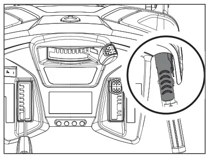
3d. Do not prime. - Stand back and to the right of the unit, pull the starter grip lightly until you feel\ resistance then pull briskly. Return the starter grip gently (Fig. 13).

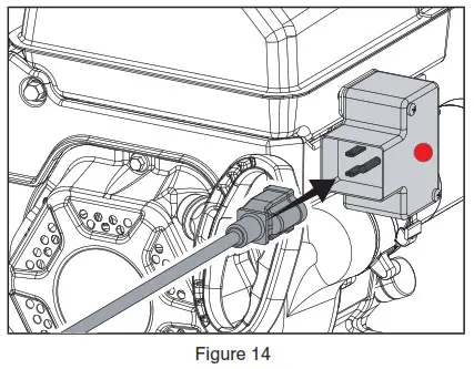
- Alternatively, for electric start, plug in the supplied electrical cord into the starter. Press the electric start button and make sure that the main supply voltage is 120 V~ 60 Hz (Fig. 14).

 3a. Move the throttle lever (12-1) to full speed. 12-1
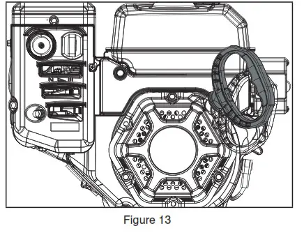
CAUTION: To prevent damaging the electric starter, do not run it more than 10 times at intervals of 5 seconds on, then 5 seconds off. If the engine does not start after this series of attempts, allow the starter to cool for at least 40 minutes before trying to start it again. If the engine still does not start, contact customer service centre for assistance 1.866.523.5218. Once started, disconnect the plug from the power supply and the starter.
OPERATION AT HIGH ALTITUDE
The density of air at high altitude is lower than at sea level. Engine power is reduced as the air mass and air-fuel ratio decrease. Engine power will be reduced approximately 3 ½% for every 1000′ (304 m) of elevation above sea level. This is a natural trend and cannot be changed by adjusting the engine. At high altitudes increased exhaust emissions can also result due to the increased enrichment of the air fuel ratio. Other high altitude issues can include hard starting, increased fuel consumption and spark plug fouling. To alleviate high altitude issues other than the natural power loss, we can provide a high altitude carburetor main jet at an additional cost.
The part number and recommended minimum altitude for the application of the high altitude carburetor main jet is listed in the following table. In order to select the correct high altitude main jet, it is necessary to identify the carburetor model. For this purpose, a code is stamped on the side of the carburetor. Select the correct high altitude jet part number corresponding to the carburetor code found on your particular carburetor.
| Carburetor Code | Main Jet | Jet Part Number | Altitude |
| Main Jet | 16161-Z151310-00A5 | ||
| 16100-Z1S0210-R901 | High Altitude | 16161-Z151110-00A1 | 914-1828 m (3000-6000′) |
| High Altitude | 16161-Z150910-00A0 | 1828-2438 m (6000-8000′) |
STOPPING THE ENGINE
To stop the engine in an emergency or during normal operation, remove the engine key (safety lock out) from the keyhole.
CONTROlS
SELF-DRIVE CONTROL LEVER.
Located on the left-side (from behind the snowblower).
When the snowblower has been put into gear, pushing this lever towards the handle engages the wheels.
Releasing the self-drive control lever causes the machine to stop moving.
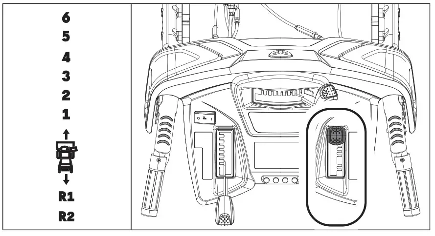
SPEED CONTROL LEVER.
Forward speeds range from slowest position 1 to fastest position 6. Reverse speeds range from slowest position R1 to fastest position R2.
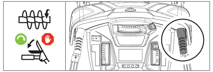
AUGER CONTROL LEVER.
Located on the right side (from behind the snowblower).
Pushing this lever towards the handle causes the auger and impeller to activate. Releasing the auger control lever causes the auger to stop moving.
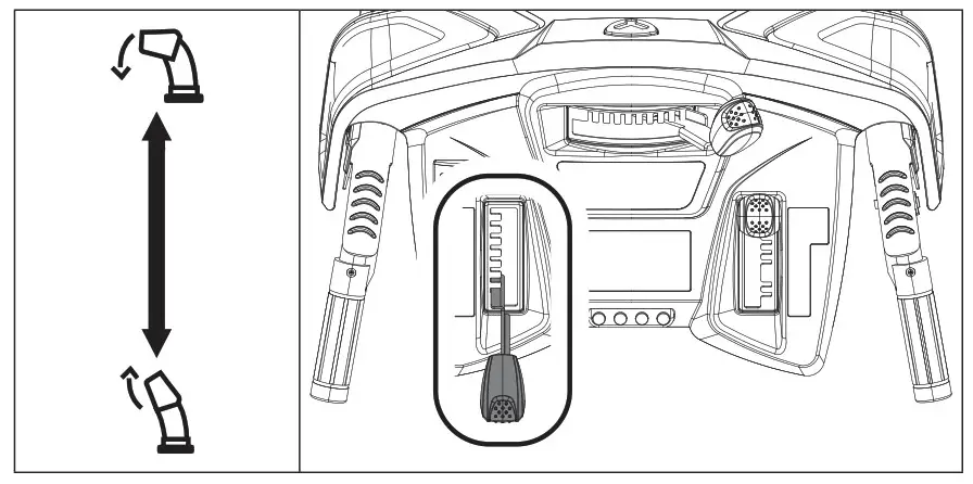
Discharge chute deflector lever controls the deflector up or down.
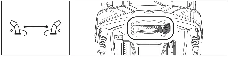
Discharge chute rotation lever controls the chute either left or right.
ADJUSTING THE SELF-PROPELLED DRIVE SYSTEM:
- Release the self-drive control lever to bring the snowblower to a stop.
- Move the speed-control lever to the gear (either forward or reverse) that you require.
- Press the self-drive control lever to engage the drive system.

Smart Steer technology enables effortless power steering on your snowblower. Smart Steer technology is able to sense the direction your trying to turn the snowblower and engages the drive system to assist turning in the desired direction.
ClUTCH lOCK FEATURE
This snowblower offers a clutch lock feature that will enable the operator to keep the snowblower moving forward while you adjust the chute. To use the clutch lock system, follow the following steps.
– While both the drive and auger control levers are fully depressed, release the auger control lever while keeping the self-drive control lever fully depressed. The clutch lock feature will automatically keep the auger control lever engaged as long as the self-drive control lever is depressed.
– This allows the operator to keep driving the snowblower while they now use their right hand to make any adjustments to the discharge chute needed to maximize operation.
– To disengage the clutch lock feature simply release the self-drive control lever.
CHANGE DISCHARGE DIRECTION:
- Move the discharge chute rotation lever either left or right.
CHANGEDISCHARGE EHEIGHT:
- Discharge chute deflector lever controls the deflector up or down.
ADJUSTING THE SNOW SHOES
– Tilt the snowblower auger back and place a spacer under the shave plate below the augers that is the height that you want the shave plate to ride above the ground.
– Loosen the bolts holding the skid shoes in place and slide the skid shoes down until they contacts the ground.
– Re-tighten the skid shoe bolts.![]() WARNING: If snow clogs the discharge chute do not try to remove it before:
WARNING: If snow clogs the discharge chute do not try to remove it before:
– Releasing the auger control handle.
– Stopping the engine.
– Disconnecting the cable from the spark plug.
Do not put your hand inside the chute or auger. Use the chute clearing tool included with your snowblower.
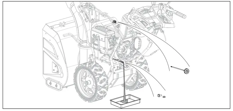
OIL CHANGE
Drain the engine oil when the engine is warm. Warm oil drains quickly and completely.
- Turn the fuel valve lever to the OFF position to reduce the possibility of fuel spillage.
- Place a suitable container below the snowblower to catch the used oil.
- Remove the drain bolt and drain the oil into the container by slightly tipping the engine toward the oil cap/dipstick.

- With the engine in a level position, fill to the upper limit mark on the dipstick with the recommended oil (0W-30).
- Reinstall the oil cap/dipstick securely.

MAINTENANCE
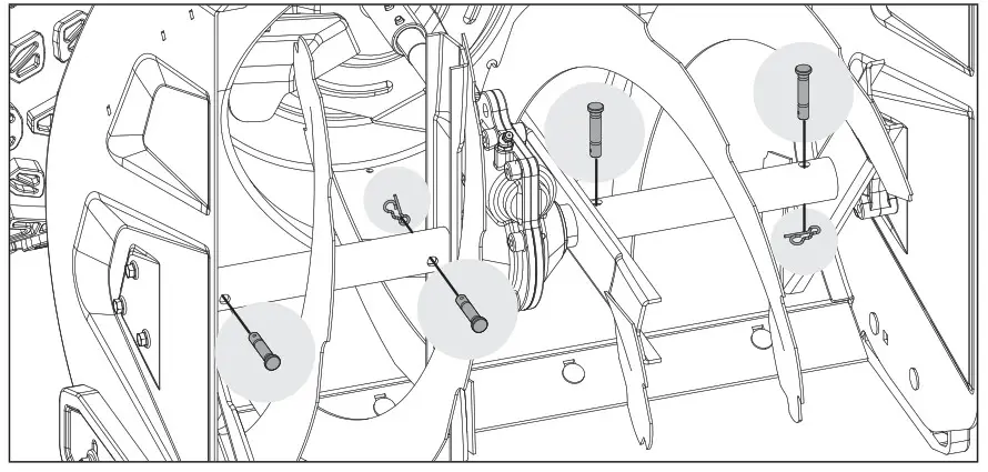
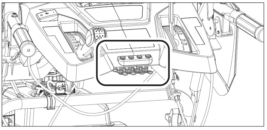
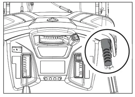
REPlACING SHEAR PINS
- The augers are secured to the spiral shaft with shear pins and clips. If the auger should strike a foreign object or ice jam, the snowblower is designed so that the pins shear.

- If the augers will not turn, check to see if the pins have sheared. Replacement shear pins and clips are found on the control panel.

Scan this QR code for video walkthroughs on the various cable adjustments
 https://yardworks.cpesupport.com
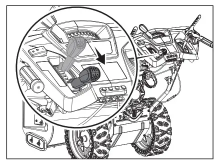
ADJUSTING SELF-DRIVE CONTROL HANDLE CABLE
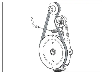
The cables are preset by the factory. Proper tension is important because you will want your snowblower to move forward properly in heavy snowfalls. You will want to perform this test when temperatures are above freezing before snow season sets in. There are 2 levels of tension in the control handles. It is best to run this test while the engine is on. Shut down the engine once you’re ready to make any adjustments. Stage 1 there is no tension, the transmission is disengaged. Stage 2 there is tension, the transmission is engaged.
If there is no stage 2, the friction disc is near end of life. Stage 1 increases slightly during long-term usage. If stage 1 is most of the control handle movement, the wheels will not rotate properly. Make adjustments as follows.
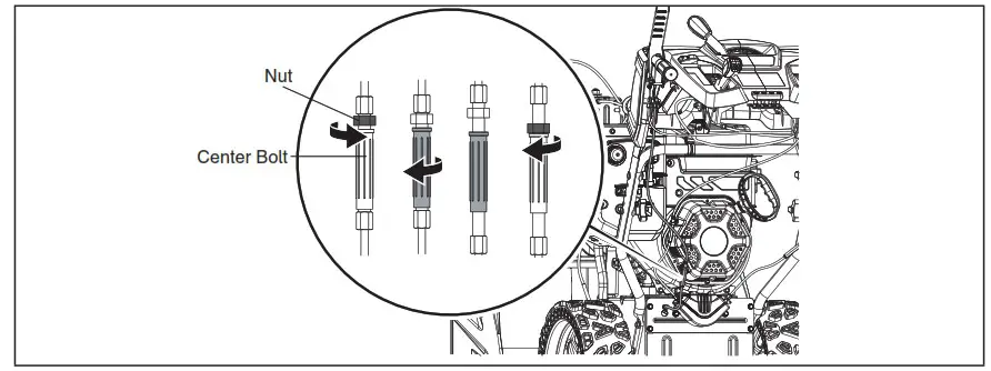
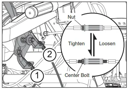
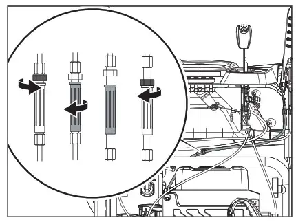
Tighten the cable and reduce the length of stage 1 to approximately what is shown above visually. Do not reduce the length of stage 1 to almost none, there will be a risk of no disengagement. Loosen the nut counterclockwise, then loosen the center bolt clockwise. Test function. Tighten the nut clockwise against the long sleeve bolt.
If the snowblower fails to drive with the drive control engaged and performing the drive control cable adjustment fails to correct the problem, the friction disc may need to be replaced. See ‘Repair or Replace Friction Disc’
If the friction disc is ok, then you should replace the cable.
If you find the wheel drives when the handle is not pressed, or when you press the handle and the wheels do not drive or rotate, the cable is most likely frozen. You should replace the cable or wait until it thaws out to test.
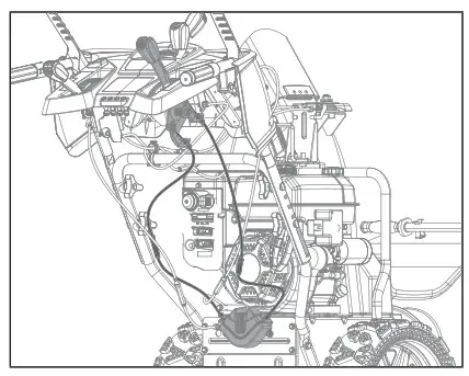
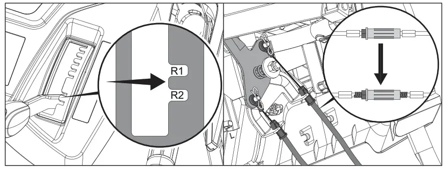
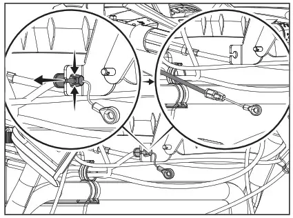
ADJUSTING SELF-DRIVE SPEED CONTROL HANDLE CABLES
- Make sure all fluids are removed and spark plug is disconnected.
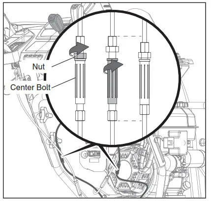
- Locate the speed control cables. There are 2 cables.

- Move the speed control lever to the fastest (top) and slowest (bottom) position. If you are able to move the lever to these 2 positions, go to the next step. If not, adjust the center bolt and nut to loosen the cable, then you can set the handle to either the fastest or slowest speeds. Loosen the nut counterclockwise, then loosen the center bolt clockwise. Test function. Tighten the nut clockwise against the long sleeve bolt.

- If you are able to adjust the speed lever to top most or bottom most position, move the lever to rest on the boss between R1 and R2 (both reverse speeds), then adjust the center bolt and nut until the cable is tight on the top most cable as shown. Do not over tighten the bolt and nut. Do not do adjust the other cable.

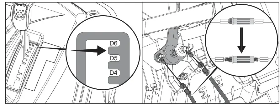
- Set the handle to the boss between D5 and D6 (top 2 forward speeds), then adjust the center bolt and nut until the cable is tight as shown. Do not over tighten the bolt and nut.

- Try the speed control lever in any position, both cables should be straight, but not overly tight in any position. If not, repeat step 3 through 5.
- Perform a speed test to confirm everything is in working order. If you’re still experiencing issues, please look at the next steps.
8. A slow speed of D1 (slowest forward speed) will be helpful for thick snow. If you want to decrease D1 speed, loosen about 1 or 2 threads for cable 1, then tighten about 1 or 2 threads for cable 2. Do not adjust too much which could set D1 in reverse.
- Check the cable is always straight when the handle at any position, then tighten these two pair of bolts and nuts.
If the snowblower speed control adjustment fails to correct the problem or the speed control will not move even with the engine on, the shift fork steering assembly may need to be replaced. See “Replace Shift Fork Steering Assembly”.
ADJUSTING AUGER CONTROL CABLE
Proper tension is important because you will want your snowblower to maximize belt life in heavy snowfalls. The belt tension controlled by the auger cable is preset by the factory. During regular usage, the auger belt will lose tension over time and need to be adjusted. If you notice your auger is not engaging, follow these steps to correct performance.
- Locate the auger control cable, connected to the auger control lever on the right-hand side from the user position.

- Locate and adjust the bolt and nut on the cable. Lengthening this nut connection will create more tension with the auger belt. Do not over adjust the cable, too much tension on belt will not allow the belt to separate from the pulley when disengaging. If the belt isn’t allowed to disengage properly, you could cause premature wearing
of the belt and ultimately cause belt failure. 3. With a helper, operate the auger control on and off with the control lever, and make sure the auger visually isn’t turning when released (Your helper would need to be a
safe distance to help you determine if the adjustments are working. They will need to view the auger or impeller rotation while you press down or release the control lever). If when released, there is a slightly turning of the auger, make slight adjustments to fine tune performance to stop the rotation when released, but working when pressed down.
 3. With a helper, operate the auger control on and off with the control lever, and make sure the auger visually isn’t turning when released (Your helper would need to be a
ADJUSTING DISCHARGE CHUTE CABLES
The snow discharge chute cables control the left and right motion of the snow discharge chute.
When you notice, either the chute isn’t turning or not turning completely, locate and adjust the bolt and nut on the cable.
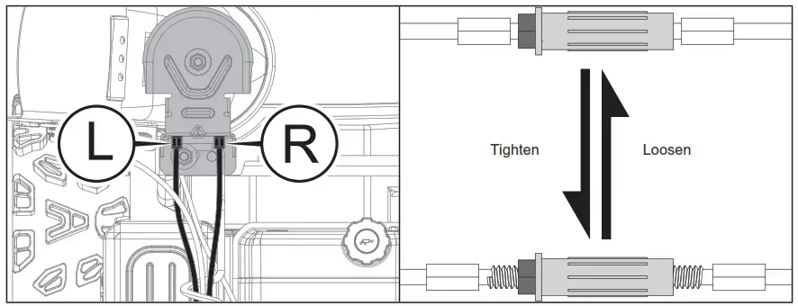
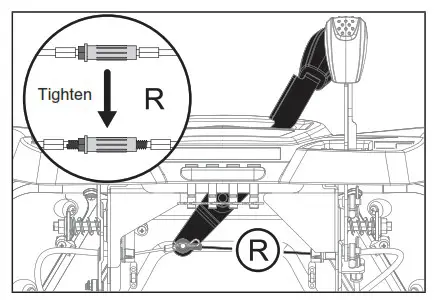
- Adjust the right cable to increase turn to max.

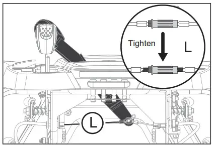
- Adjust the left cable to increase turn to max. Loosen the nut counterclockwise, then loosen the center bolt clockwise. Test function. Tighten the nut clockwise against the long sleeve bolt.

REPLACE DISCHARGE CHUTE DEFLECTOR CABLE
Make sure all fluids are removed and spark plug is disconnected.
To remove and replace your snowblower’s chute deflector cable, proceed as follows:
- Adjust the deflector in its full, upright position.

- Remove the B pin.

- Remove the anchor pin by sliding it off.

- On the control panel side, press the cable busing tabs and pull it out. Be careful not to damage the tabs.

- On the chute side, press the cable busing tabs and pull it out. Be careful not to damage the tabs.

- Remove the cable end from the bracket.

- Follow the reverse steps to replace the cable.
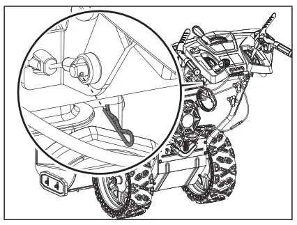
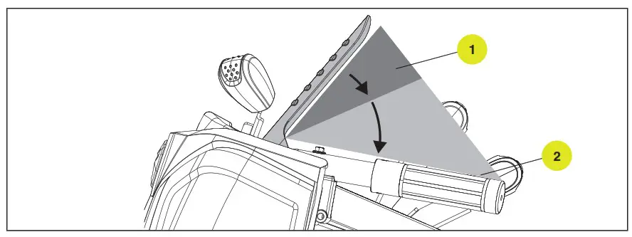
REPLACE SELF-DRIVE CONTROL HANDLE CABLE
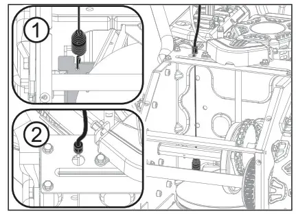
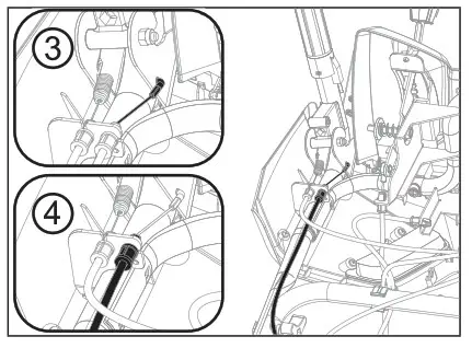
- Carefully pivot the snowblower up and forward so that it rests on the auger housing. Place a piece of cardboard or moving blanket on the ground before tipping forward. Make sure all fluids are removed and spark plug is disconnected.
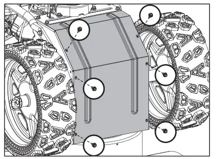
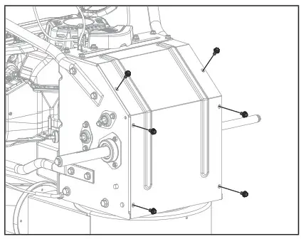
- Remove the base frame cover (1) from the underside of the snowblower by removing the six M6 × 16 screws which secures it.

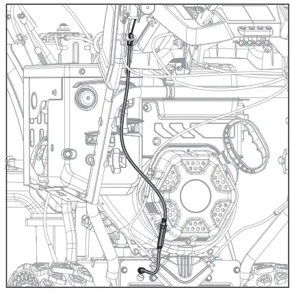
- Locate the self-drive cable.

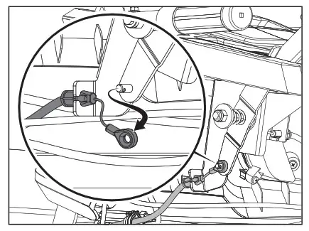
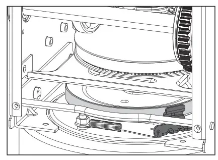
- Unhook the spring from the drive plate hole (1).
- Squeeze and remove the strain relief from the machine side (2).

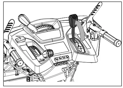
- Unhook the connector in the control handle. You may have to move the control handle to make these easier to remove (3).
- Squeeze and remove the strain relief from the control handle side (4).
- Perform the steps in reverse with the new cable.

REPLACE AUGER BELT
Make sure all fluids are removed and spark plug is disconnected.
Tools required:
- 10mm size wrench.
- 13mm wrench.
To remove and replace your snowblower’s auger belt, proceed as follows:
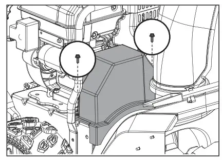
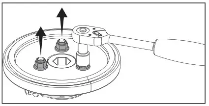
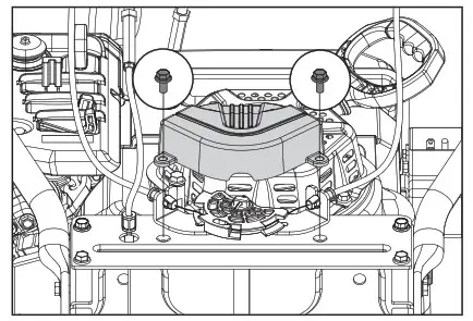
- Remove the plastic belt cover on the front of the engine by removing two M6 × 16 bolts.

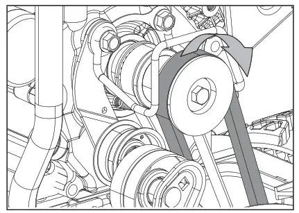
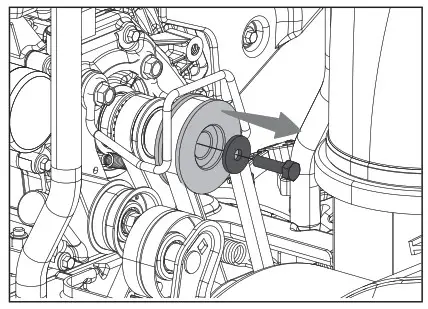
- Slip the old auger drive belt over the auger drive pulley. If you are unable to remove the belt in this step, please disassemble the engine pulley in the next step.

- Remove the engine pulley and washer.

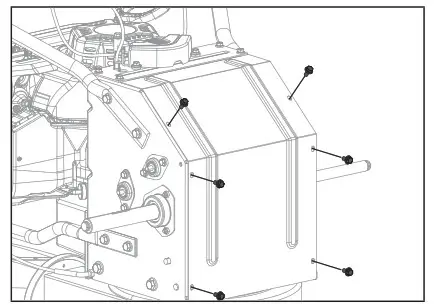
- Carefully pivot the snowblower up and forward so that it rests on the auger housing. Place a piece of cardboard or moving blanket on the ground before tipping forward.
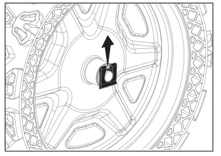
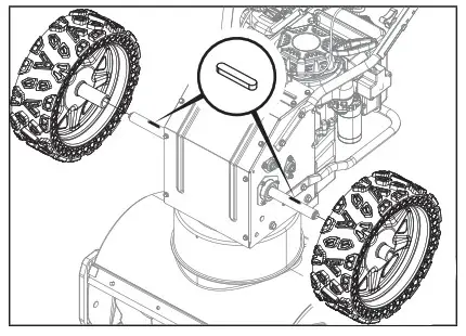
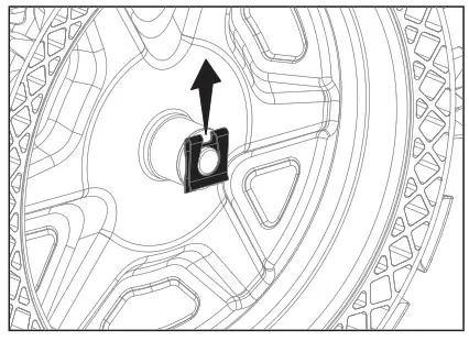
- Remove the wheels by first removing the wheel clip and then sliding the wheels of the axles.

- Save the key from each wheel. Do not lose each key from each wheel. You will need this when you put it back together.

- Remove the base frame cover from the underside of the snowblower by removing the six M6 × 16 screws which secure it.

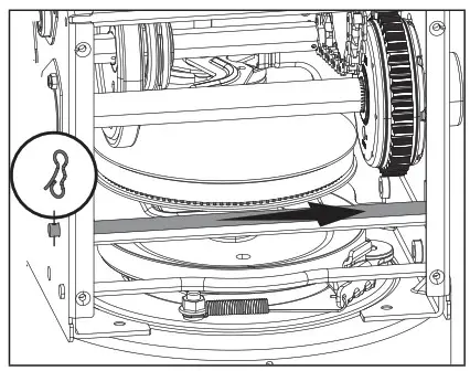
- Remove the connecting shaft as shown by removing the B clip and sliding the rod out of the way. This will allow you to move the friction disc away from the large auger pulley. Remove the auger belt from the larger pulley.

 WARNING: If cutting the belt be careful of the tensioning pulley and arm as they are spring loaded and could cause injury when the belt is cut.
 - Slide the speed adjusting handle to position 6 (fastest forward speed) to move the rubber ring assembly to the edge of the friction disc. Then remove the loose belt by cutting it. If the belt has already broken, then remove any remaining belt pieces.

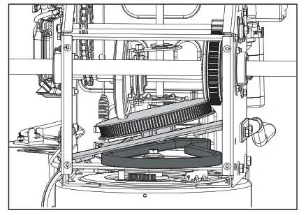
- Slip the new auger drive belt into the compartment from the bottom of the snowblower placing it around the bottom of the auger drive pulley and slipping it around the front pulley on the engine. Ensure the belt is positioned between the bottom belt guard and the bottom of the auger drive pulley.

- Ensure belt is seated below the belt brake on the idler pulley pivot arm.

- Reassemble / reattach the base frame cover.

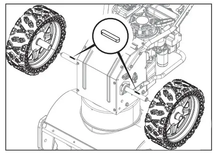
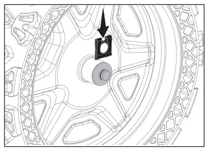
- Reattach the wheels. Slide the key into the keyway of the axle and align the slot on the wheel hub.

- Attach the wheel clip until it clicks into place.

- Turn the snowblower right side up. With the belt properly placed on both the front pulley and the auger drive pulley, pull the auger idler pulley back away from the belt and slip the belt inside the pulley. You can pull the recoil to rotate the pulley to help get it seated.

- Pull the auger control handle to ensure the idler pulley is properly engaging the belt. Under the belt cover area, make sure the distance on both sides between the guide and pulley is the same.

- Carefully pivot the snowblower up and forward so that it rests on the auger housing. Place a piece of cardboard or moving blanket on the ground before tipping forward. Reinstall the base frame cover.
- Turn the snowblower right side up. Install the plastic belt cover using two M6 × 16 bolts set aside from an earlier step. Torque until snug. Do not overtighten or you risk damaging the plastic belt cover.
- Perform a drive test to confirm everything is in working order.
REPAIR OR REPLACE FRICTION DISC
Make sure all fluids are removed and spark plug is disconnected.
Tools required:
- 12 size wrench.
- 19 size wrench.
To remove and replace your snowblower’s friction disc, proceed as follows:
- Carefully pivot the snowblower up and forward so that it rests on the auger housing. Place a piece of cardboard or moving blanket on the ground before tipping forward. Make sure all fluids are removed and spark plug is disconnected.
- Remove the wheels by first removing the wheel clip and then sliding the wheels of the axles.

- Save the key from each wheel. Do not lose each key from each wheel. You will need this when you put it back together.

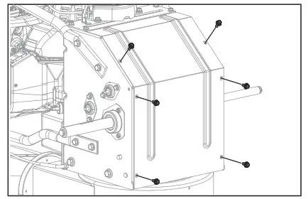
- Remove the base frame cover (1) from the underside of the snowblower by removing the six M6 × 16 screws which secure it.

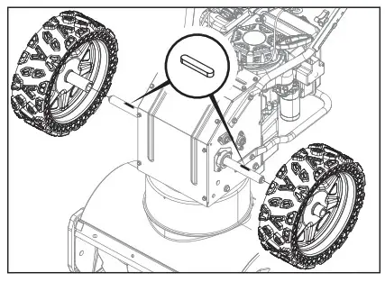
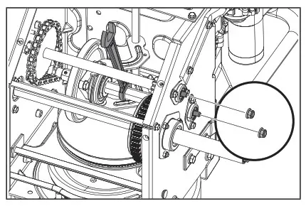
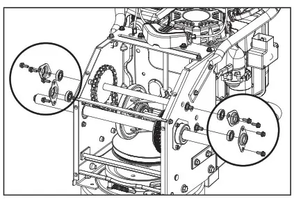
- Carefully remove the M8 hex nut on each side which secures the hex shaft and chain gear shaft to the snowblower frame. Use a 19mm or adjustable wrench to hold the center of the hex shaft and use a 12mm socket to remove the nuts on each side.

- Carefully remove the M6 hex bolt on each side which secures the bearings to the snowblower frame. Use a 13mm socket to remove the nuts and bearings on each side.

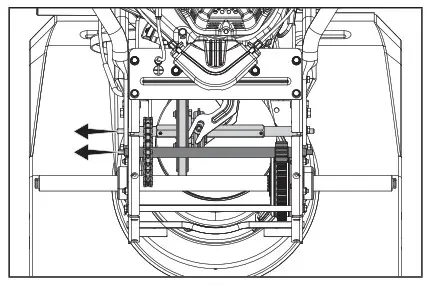
- Slide the speed adjusting handle to the position 6 (fastest forward speed) and slide out the hex shaft and chain gear shaft.
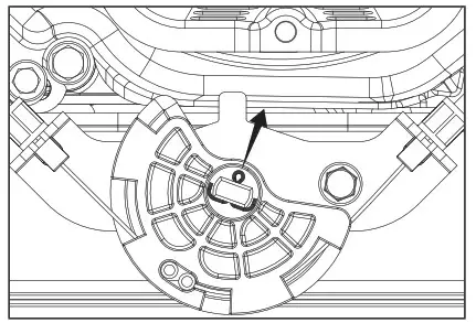
 8. With the hex shaft removed, pulled out the spring pin shown and slide the disc off.
- Unscrew the three M8 bolts of the friction disc assembly to discard the worn friction wheel rubber ring and replace with a new one. Use 3 new self-locking nuts to assemble a new rubber ring, do not over tighten.
- Clean the aluminum friction disc by wiping down with a clean cloth and follow the previous steps in reverse order to reassemble the parts.

 8. With the hex shaft removed, pulled out the spring pin shown and slide the disc off.
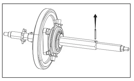
REPlACE SHIfT FORK STEERING ASSEMBLY
If the snowblower speed control will not move even with the engine on, check these two cables, whether the center bolts are too tight found in ‘Adjusting Self-Drive Speed Control Handle Cables’ section. If so, loosen the cables slightly by unthreading the center nut. If the adjustments do not correct the issues, considering replacing the gear shift fork assembly. Make sure all fluids are removed and spark plug is disconnected.
Tools required:
- 10mm size wrench
To remove and replace your snowblower’s shift fork assembly, proceed as follows:
- See Repair or Replace Friction Disc step 1-7, as the shift fork can only be removed when the hex shaft is removed.
- Carefully pivot the snowblower up and forward so that it rests on the auger housing. Place a piece of cardboard or moving blanket on the ground before tipping forward. Make sure all fluids are removed and spark plug is disconnected.
- Remove the Shift Fork Cover by removing the 2 M6 × 16 screws which secures it.

- Remove the cotter pin holding the Shift Fork Steering Unit on.

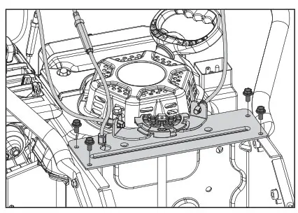
- Remove the shift fork assembly plate by remove 4x M6x16mm bolts.
- Remove the shift fork.
- Reverse the steps to reassemble. If you find it hard to align the shift fork shaft and the plastic drive plate hole, loosen two speed control cables. Don’t forget to adjust and tighten the nut in the cable adjustment in section Adjusting Self-Drive Speed Control Handle Cables.
- Perform a speed test to confirm everything is in working order.

VALVE ClEARANCE
If set in summer: (if set at room temperature about 50°F – 86°F (10°C-30°C) intake clearance 0.10~0.15mm (.004”-.006”) exhaust clearance 0.15~0.20mm (.006”-.008”)
If set in winter: (if set in cold at < 32°F (0°C) then recommend setting a little tighter at: intake clearance 0.05~0.10mm (.002”-.004”) exhaust clearance 0.10~0.15mm (.004”-.006”)
LUBRICATION
No parts inside the gearbox are to be lubricated. All bearings and bushings are permanently lubricated and require no maintenance. Lubricating these parts will only result in the grease getting on to the friction wheel and disc drive plate, which could damage the rubber clad friction wheel.
LONG-TERM STORAGE
Never store the machine with gasoline in the fuel tank in a confined area with bad ventilation. Gasoline fumes could reach open flames, sparks, cigarettes, etc.
To avoid the engine freezing and problems starting the engine, leave the engine running for 5-10 minutes after your work has been completed. This will ensure all moisture will disappear that would otherwise cause starting problems.
If the machine is to be stored for a longer period than 30 days, the following procedures are recommended.
- Mix fuel stabilizer with gasoline according to fuel stabilizer manufacturer’s directions.
- Start the engine and let it run until it stops due to lack of fuel.
- Change the engine oil if it has not been done for 3 months.
- Remove the spark plug and empty a little engine oil (about 1 oz {30 mL}) in the hole. Crank the engine a couple of times. Replace the spark plug.
- Clean the whole machine thoroughly.
- Inspect the machine for damage, and repair if necessary.
- Apply rust protection to the metal surfaces.
- Store the machine indoors if possible.
TRANSPORTING
If the engine has been running, allow it to cool for at least 15 minutes before loading the machine on the transport vehicle. A hot engine and exhaust system can burn you and can ignite some materials.
Keep the engine level when transporting to reduce the possibility of fuel leakage. Move the fuel valve lever to the OFF position.
REGUlAR SERVICE PERIODS
Perform at every indicated month or operating hour interval, whichever comes first.
| Item | Service | Each Use | Every month or 20 hrs. | Every 3 months or 50 hrs. | Every 6 months or 100 hrs. | Every year or 150 hrs. |
| Engine Oil | Check level | ❑ | ||||
| Change | ❑ | |||||
| Spark Plug | Check/Clean | ❑ | ||||
| Replace | ❑ | |||||
| Spark Arrester (optional parts) | Clean | ❑ | ||||
| Idle Speed | Check-adjust | ❑(1) | ||||
| Valve Clearance | Check-adjust | ❑(1) | ||||
| Fuel Tank and Strainer | Clean | ❑(1) | ||||
| Fuel Line | Check | Every 2 years (replace if necessary) (1) | ||||
- These items should be serviced by your servicing dealer unless you have the proper tools and are mechanically proficient.
![]() WARNING: Never operate a damaged or defective snow blower.
WARNING: Never operate a damaged or defective snow blower.![]() WARNING: Improper maintenance will void your warranty.
WARNING: Improper maintenance will void your warranty.![]() NOTIC: For Emission control devices and systems, read and understand your responsibilities for service as stated in the Emission Control Warranty Statement of this manual.
NOTIC: For Emission control devices and systems, read and understand your responsibilities for service as stated in the Emission Control Warranty Statement of this manual.
TROUBLESHOOTING
| PROBLEM | POSSIBLE CAUSE | REMEDY |
| Engine fails to start. | Engine flooded. Water in fuel. Other. Red ignition key pulled out or missing | Repeat start attempts with choke OFF. Drain tank and refill with fresh fuel. Check carefully the start procedure according to this manual. Push in red key. If key is lost, you may use a wood Popsicle stick as a temporary key until Red key is found or replaced. |
| Engine starts hard or runs poorly. | Spark plug issues. Fuel cap ventilation is blocked. | Replace the spark plug. Clear the ventilation or replace cap. |
| Auger does not rotate. | Foreign material caught in system. Auger drive belt slipping. Auger drive belt broken. | Clean. Adjust the belt cable to increase tension Replace the belt. |
| Auger does not stop when the lever is released. | Auger drive belt is out of adjustment. Auger drive guide is out of adjustment. | Adjust the belt cable to decrease tension. Adjust the guide. |
| Snowblower veers to one side. | Wheel spring lock pin is inserted on one side. Shoes are mounted unevenly. Scraper blade uneven. | Check the wheel locks. Adjust shoes. Adjust scraper blade and shoes. |
| Snowblower does not drive. | Drive belt worn/broken. Friction disc worn out. Drive belt slipping Oil or grease contamination on aluminum drive disc. Water drip onto aluminum drive disk | Replace traction drive belt. Repair or replace friction disc. Adjust the belt cable to increase tension. Clean off aluminum drive disk with solvent, such as, brake cleaner. Sometimes wet snow near 0°C (32°F) may melt and drip onto aluminum drive disc. Wait 2-4 minutes for the water to evaporate and then try wheel drive. |
WARRANTY
4-YEAR LIMITED WARRANTY
For Four YEARS from the date of purchase within Canada, YARDWORKS CANADA will, at its option, repair or replace for the original purchaser, free of charge, any part or parts found to be defective in material or workmanship.
THIS WARRANTY DOES NOT COVER:
- Any part that has become inoperative due to misuse, commercial use, abuse, neglect, accident, improper maintenance, or alteration;
- The unit, if it has not been operated and/or maintained in accordance with the owner’s manual;
- Normal wear parts like belts, skid shoes and shave plates except as noted below;
- Routine maintenance items such as oil, spark plug, fuel line; or
- Normal deterioration of the exterior finish due to use or exposure.
FULL 270-DAY WARRANTY ON NORMAL WEAR PARTS:
Normal wear parts are defined as wheels, tires, belts, drive disc, skid shoes and shave plate. These parts are warranted to the original purchaser to be free from defects in material and workmanship for a period of two hundred seventy (270) days from the d ate of retail purchase.
HOW TO OBTAIN SERVICE:
Warranty service is available by calling the toll-free helpline at 1.866.523.5218.
The factory will not accept the return of a complete unit unless prior written permission has been extended by YARDWORKS CANADA.
TRANSPORTATION CHARGES:
Transportation charges for the movement of the snowblower or accessories are the responsibility of the purchaser. The purchaser must pay transportation charges for any part submitted for replacement under this warranty unless such return is requested in writing by YARDWORKS CANADA.
OTHER WARRANTIES:
All other warranties, express or implied, including any implied warranty of merchantability is limited in its duration to that set forth in this express limited warranty. The provisions as set forth in this warranty provide the sole and exclusive remedy of YARDWORKS CANADA obligations arising from the sale of its products.
ADDITIONAl lIMITATIONS
This warranty applies only to the original purchaser and may not be transferred. Neither the retailer nor the manufacturer shall be liable for any other expense, loss or damage, including, without limitation, any indirect, incidental, consequential or exemplary damages arising in connection with the sale, use or inability to use this product.
NOTICE TO CONSUMER
This warranty gives you specific legal rights, and you may have other rights, which may vary from province to province. The provisions contained in this warranty are not intended to limit, modify, take away from, disclaim or exclude any statutory warranties set forth in any applicable provincial or federal legislation.
Made in China
Imported by
Trileaf Distribution Toronto, Canada M4S 2B8
YARDWORKS CANADA will not be liable for incidental or consequential loss or damage.
CHAMPION POWER EQUIPMENT, INC. (CPE) AND UNITED STATES ENVIRONMENT PROTECTION AGENCY (U.S. EPA) EMISSION CONTROL SYSTEM WARRANTY
Your Champion Power Equipment (CPE) engine complies with U.S. EPA emissions regulations.
YOUR WARRANTY RIGHTS AND OBLIGATIONS:
The US EPA and CPE are pleased to explain the Federal Emission Control Systems Warranty on your 2022 small off-road engine (SORE) and engine powered equipment. New engines and equipment must be designed, built and equipped, at the time of sale, to meet U.S. EPA regulations for small off-road engines (SORE). CPE warrants the emission control system on your small off-road engine (SORE) and equipment for the period of time listed below, provided there has been no abuse, neglect, unapproved modification, or improper maintenance of your equipment. Your emission control system may include parts such as the carburetor, fuel-injection system, the ignition system, catalytic converter and fuel lines. Also included may be hoses, belts, connectors and other emission related assemblies. Where a warrantable condition exits, CPE will repair your small off-road engine (SORE) at no cost to you including diagnosis, parts and labor.
MANUFACTURER’S EMISSION CONTROL SYSTEM WARRANTY COVERAGE:
This emission control system is warranted for two years, subject to provisions set forth below. If, during the warranty period, an emission related part on your engine is defective in materials or workmanship, the part will be repaired or replaced by CPE.
OWNER WARRANTY RESPONSIBILITIES:
As the small off-road engine (SORE) owner, you are responsible for the performance of the required maintenance listed in your Owner’s Manual. CPE recommends that you retain all your receipts covering maintenance on your small off-road engine, but CPE cannot deny warranty solely for the lack of receipts or for your failure to ensure the performance of all scheduled maintenance.
As the small off-road engine (SORE) owner, you should however be aware that CPE may deny you warranty coverage if your small, off-road engine (SORE) or a part has failed due to abuse, neglect, improper maintenance or unapproved modifications.
You are responsible for presenting your small off-road engine (SORE) to an Authorized CPE service outlet or alternate service outlet as described in (3)(f.) below, CPE dealer or CPE, Santa Fe Springs, Ca. as soon as a problem exists. The warranty repairs should be completed in a reasonable amount of time, not to exceed 30 days.
If you have any questions regarding your warranty rights and responsibilities, you should contact:
Champion Power Equipment, Inc.
Customer Service
12039 Smith Ave.
Santa Fe Springs, CA 90670
1-877-338-0999
[email protected]
EMISSION CONTROL SYSTEM WARRANTY
The following are specific provisions relative to your Emission Control System (ECS) Warranty Coverage.
- APPLICABILITY: This warranty shall apply to 1997 and later model year small off-road engines (SORE). The ECS Warranty Period shall begin on the date the new engine or equipment is delivered to its original, end-use purchaser, and shall continue for 24 consecutive months thereafter.
- GENERAL EMISSIONS WARRANTY COVERAGE
CPE warrants to the original, end-use purchaser of the new engine or equipment and to each subsequent purchaser that each of its small off-road engines (SORE) is:
2a. Designed, built and equipped so as to conform to U.S. EPA emissions standards for spark-ignited engines at or below 19 kilowatts.
2b. Free from defects in materials and workmanship that cause the failure of a warranted part to be identical in all material respects to the part as described in the engine manufacturer’s application for certification for a period of two years. - THE WARRANTY ON EMISSION-RELATED PARTS WILL BE INTERPRETED AS FOLLOWS:
3a. Any warranted part that is not scheduled for replacement as required maintenance in the Owners Manual shall be warranted for the ECS Warranty Period. If any such part fails during the ECS Warranty Period, it shall be repaired or replaced by CPE according to Subsection “d” below. Any such part repaired or replaced under the ECS Warranty shall be warranted for any remainder of the ECS Warranty Period.
3b. Any warranted, emissions-related part which is scheduled only for regular inspection as specified in the Owners Manual shall be warranted for the ECS Warranty Period. A statement in such written instructions to the effect of “repair or replace as necessary”, shall not reduce the ECS Warranty Period. Any such part repaired or replaced under the ECS Warranty shall be warranted for the remainder of the ECS Warranty Period.
3c. Any warranted, emissions-related part which is scheduled for replacement as required maintenance in the Owner’s Manual shall be warranted for the period of time prior to the first scheduled replacement point for that part. If the part fails prior to the first scheduled replacement, the part shall be repaired or replaced by CPE according to Subsection “d” below. Any such emissions-related part repaired or replaced under the ECS Warranty, shall be warranted for the remainder of the ECS Warranty Period prior to the first scheduled replacement point for such emissions-related part.
3d. Repair or replacement of any warranted, emissions-related part under this ECS Warranty shall be performed at no charge to the owner at a CPE Authorized Service Outlet.
3e. The owner shall not be charged for diagnostic labor which leads to the determination that a part covered by the ECS Warranty is in fact defective, provided that such diagnostic work is performed at a CPE Authorized Service Outlet.
3f. CPE shall pay for covered emissions warranty repairs at non-authorized service outlets under the following circumstances:
i. The service is required in a population center with a population over 100,000 according to U.S. Census 2000 without a CPE Authorized Service Outlet AND
ii. The service is required more than 100 miles from a CPE Authorized Service Outlet. The 100 mile limitation does not apply in the following states: Alaska, Arizona, Colorado, Hawaii, Idaho, Montana, Nebraska, Nevada, New Mexico, Oregon, Texas, Utah and Wyoming.
3g. CPE shall be liable for damages to other original engine components or approved modifications proximately caused by a failure under warranty of an emission-related part covered by the ECS Warranty.
3h. Throughout the ECS Warranty Period, CPE shall maintain a supply of warranted emission-related parts sufficient to meet the expected demand for such emission-related parts.
3i. Any CPE Authorized and approved emission-related replacement part may be used in the performance of any ECS Warranty maintenance or repair and will be provided without charge to the owner. Such use shall not reduce CPE’s warranty obligation.
3j. Unapproved add-on or modified parts may not be used to modify or repair a CPE engine. Such use voids this ECS Warranty and shall be sufficient grounds for disallowing an ECS Warranty claim. CPE shall not be liable hereunder for failures of any warranted parts of a CPE engine caused by the use of such an unapproved add-on or modified part.
EMISSION-RELATED PARTS INCLUDE THE FOLLOWING:
(using those portions of the list applicable to the engine)
| Systems covered by this warranty | Parts Description |
| Fuel Metering System | Fuel regulator, Carburetor and internal parts |
| Air Induction System | Air cleaner, Intake manifold |
| Ignition System | Spark plug and parts, Magneto ignition system |
| Exhaust System | Exhaust manifold, catalytic converter |
| Miscellaneous Parts | Tubing, Fittings, Seals, Gaskets, and Clamps associated with these listed systems. |
| Evaporative Emissions | Fuel Tank, Fuel Cap, Fuel Lines (for liquid fuel and fuel vapors), Fuel Line Fittings, Clamps, Pressure Relief Valves, Control Valves, Control Solenoids, Electronic Controls, Vacuum Control Diaphragms, Control Cables, Control Linkages, Purge Valves, Gaskets, Liquid/Vapor Separator, Carbon Canister, Canister Mounting Brackets, Carburetor Purge Port Connector |
TO OBTAIN WARRANTY SERVICE:
You must take your CPE engine or the product on which it is installed, along with your warranty registration card or other proof of original purchase date, at your expense, to any Champion Power Equipment dealer who is authorized by Champion Power Equipment, Inc. to sell and service that CPE product during his normal business hours. Alternate service locations defined in Section (3)(f.) above must be approved by CPE prior to service. Claims for repair or adjustment found to be caused solely by defects in material or workmanship will not be denied because the engine was not properly maintained and used.
If you have any questions regarding your warranty rights and responsibilities, or to obtain warranty service, please write or call Customer Service at Champion Power Equipment, Inc.
![]() Champion Power Equipment, Inc.
Champion Power Equipment, Inc.
12039 Smith Ave.
Santa Fe Springs, CA 90670
1-877-338-0999
Attn.: Customer Service
[email protected]


