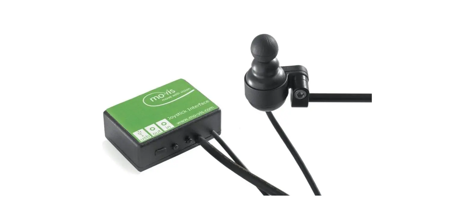
mo-vis P002-51, P002-52 Micro Joystick

About this manual
Installation manual
This manual contains useful and important information about your device. Please read it carefully before use and store safely for future reference. Our team will be happy to answer your questions.
mo-vis bv
Biebuyckstraat 15D. 9850 Deinze. Belgium
http://www.mo-vis.com. [email protected]. +32 9 335 28 60
Important information
CAUTION: Incorrect use or installation may lead to risk of injury to the user and damage to the wheelchair or other property. In order to reduce these risks, you should carefully read this installation manual, paying particular attention to the safety instructions and warning texts.
NOTICE: Only install this product on a wheelchair where the wheelchair manufacturer allows the installation of third-party parts.
Warranty
mo-vis bv warrants the product to be free from defects in material and workmanship for a period of 2 years under proper use, care and service. The dealer should never keep mo-vis products in stock for a period more than 6 months prior to delivery to the end user. movies warranty will never exceed a period of 2 years and 6 months after shipment. All warranties do not extend beyond the initial purchaser from an authorized mo-vis dealer or mo-vis itself.
Repair and replacement
For warranty service, contact your dealer (or us if bought directly). In the event of a defect in material or workmanship, the dealer or customer must obtain a Return Merchandise Authorization (RMA) number from us. The product must be shipped to a service centre designated by mo-vis. mo-vis will repair or, at mo-vis’ option, replace any product covered by the warranty.
Amendments
No person is authorized to alter, extend or waive the warranties of mo-vis.
Disclaimer and limitations of remedies
The express warranties set forth in this agreement are in lieu of all other warranties of merchantability or fitness of purpose. In no event shall movis be liable for any direct, indirect, incidental or consequential damages resulting from any defect in this product. Warranty of parts subject to “normal wear and tear” (e.g. joystick handles, pads, …) are not covered in the warranty except as it applies to defects in material or construction.
Voiding of warranties
The foregoing warranties are contingent upon the proper installation, use, maintenance and care of the product. The warranty will be void if the product has been installed or used improperly, or if it has been repaired or any part replaced by persons other than mo-vis or an authorized dealer. This product is considered as a non-serviceable part. The addition of equipment or features that are not manufactured or recommended by mo-vis could affect the intended function of the mo-vis product and may invalidate the warranty.
Technical support
TROUBLE:
In case of technical problems:
- Contact mo-vis at [email protected] or +32 9 335 28 60.
- Always state the device serial number when contacting us. This ensures you are provided with the correct information.
Warning labels
Please read this manual, the safety instructions and warning texts carefully, in order to reduce the risks associated to the device. Our products are safe under normal and reasonably foreseeable operating conditions.
NOTE: This symbol indicates general notes and information.
CAUTION: This symbol indicates caution for a hazardous situation that, if not avoided, could result in minor or moderate injury.
WARNING: This symbol indicates a warning for a hazardous situation that, if not avoided, could result in death or serious injury.
Limited liability
mo-vis accepts no liability for personal injury or damage to property that may arise from the failure of the user or other persons to follow the recommendations, warnings and instructions in this manual.
CAUTION: Carry out only the service and maintenance activities specified in this manual, as long as you comply with the demands stated in this manual for a specific action. In case of doubt, contact movis.
WARNING: The device should always be tested without any person sitting in the wheelchair after every alteration of the physical installation or adjustment of the parameters.
Preparations
CAUTION: Before you start with the installation:
- Please check the packaging and verify that all items are included.
- Make sure that you have all the necessary documentation and knowledge to install this device.
- Check the condition of the device.
Qualified service engineer
Only a qualified service engineer may install the device.
CAUTION: An incorrect programming of the wheelchair electronics may cause damage to the devices, or injury to the user.
Tools
Use an Allen wrench to install the device.
CAUTION: Use proper tools to install and adjust the device. The use of improper tools may cause damage to the device.
Installation plan
Set up an installation plan before beginning the installation. Based on the users’ needs and capabilities, this plan should take into account:
- Where which part of the device should be placed.
- How the device will be operated.
- A robust and reliable positioning. Hard or sudden movements of the wheelchair may not disorganize the installation.
WARNING: Protect the device against bumps. Mind damaging the unit and wiring. Make sure that cabling is mounted in such a way that excessive wear and tear is avoided.
WARNING: Do not use the joystick as only support for hands or limbs. Movements and shocks may disrupt controls.
Installation
- Define the position of the joystick.
When the arrow at the bottom of the joystick points to the front, a forward movement of the joystick will result in an according forward movement of the wheelchair. If needed, you can change this positioning in steps of 90° with the Configurator Software. - Place the mounting ring around the joystick housing.
- Secure the Q2M half clamp to the mounting ring. Use an Allen wrench to mount the 20 mm bolt.
NOTE: It is not advised, but you may mount the joystick without using the Q2M half clamp.
CAUTION: Tighten the screws firmly, but not excessively. Excessive force may damage the unit. - Slide the unit over a Q2M Rod, or any other 6 mm rod, to position the Micro Joystick on the wheelchair. A Q2M Rod D6 50 mm is included in your package, but you can use any other Q2M Rod (e.g. a C- or S-Rod from the Multi Swing).
- Place and secure the interface unit and all cabling on the wheelchair.
- Place a power on/off (pwr) and/or mode (in) switch, secure their cabling, and insert their connections. You can use the connections on the Interface unit.
CAUTION: Before inserting a connector, remove the protective cover. If the connections are not used, always put or keep the protective covers in.
CAUTION: This is Class I Medical Device (MDR 2017/745). All accessories, including switches, must also comply with the MDR 2017/745 regulations (e.g. the mo-vis Twister, tested according to EN12184 standards). - Connect the cabling to the wheelchair electronics.
CAUTION: All wheelchair electronics must be switched off during installation.
Operation
The movements of the joystick are translated into according movements of the wheelchair, e.g. driving or menu navigation.
Common practice to navigate the wheelchair with the joystick is as follows:
- Direction: point the joystick into the direction you want the wheelchair to move. The wheelchair then moves in that direction.
- Speed: the further you move the joystick from the default (center) position, the faster the wheelchair moves.
- Stop: whenever you release the joystick, the joystick moves back to the default (center) position and the wheelchair stops.
CAUTION: Avoid hitting obstacles during driving.
WARNING: When the LED light flashes and/or after every incident with the wheelchair or the mo-vis device, contact your dealer immediately to perform a functional test.
Configuration
WARNING: Changes in parameter settings may cause damage to the device or power chair, or may cause injury to people.
CAUTION: Always change parameters and test the outcome without anyone sitting in the power chair?
Software Download
- You can download the Configurator Software on our website http://www.mo-vis.com
- Software requirement: Windows version 10
- For all details on how to install and use the software, we refer you to the Configurator Software manual.
- To configure the parameters of the device, you need dealer-level access.
This level is password-protected. Contact mo-vis to obtain the password.
NOTE: Never share your password with anyone and keep access to the Configurator Software is strictly personal.
Defining parameter settings
- Connect the device to a PC. Use a standard mini-USB-USB cable.
CAUTION: Before inserting a jack or USB cable, remove the protective cover. If the connections are not used, always put or keep the protective covers in. - Configure the parameters with the software.
- Upload the configuration.
- Test the configuration and adjust if necessary.
Parameter settings
| SETTING | DESCRIPTION | PARAMETERS | ||
| Mounting direction | It can be easier to mechan- ically mount the joystick under an angle. This func- tion swaps the joystick axis per 90° clockwise, to com- pensate for the rotation of the joystick. | 0° | Default | |
| 0° | Min. | |||
| 270° | Max. | |||
| 90° | Step | |||
| Dead band | Neutral zone around the | 5% | Default | |
| joystick center position. | ||||
| 5% | Min. | |||
| Prevents creeping of the | ||||
| wheelchair after releasing | ||||
| 10% | Max. | |||
| the joystick. | ||||
| 1 | Step | |||
| NOTE: Most | ||||
| wheelchair | ||||
| electronics have | ||||
| their own dead band | ||||
| setting. It is advised | ||||
| to keep the default | ||||
| setting of the mo-vis | ||||
| device. | ||||
| SETTING | DESCRIPTION | PARAMETERS | |
| Compensa- tion mode | Defines activation of the compensation algorithm. | Off | Always deacti- vated |
| For R-net: can be set indi- vidually for each profile. | Manual | (De)activated manually by the user | |
| On | Always acti- vated | ||
| Compensa- tion factor | Lowers forward/backward (Y) driving speed on rough terrain. Wheelchair type and weight have an impact on this fac- tor: | Very weak | Almost no slow down |
| Weak | Slows down less compared to normal | ||
| • Heavy loaded wheelchairs may need to lower the setting to ‘Weak’. • Light wheelchairs may need to increase the | Normal | Default set- ting | |
| Strong | Slows down more com- pared to nor- mal | ||
| SETTING | DESCRIPTION | PARAMETERS | |
| setting to ‘Strong’. • If the joystick is mounted on a location that may multiply the value of a shock (e.g. on an arm), the setting should be lowered to ‘Weak’ or ‘Very weak’. | Very strong | Slows down more com- pared to strong | |
| • Frontwheel-driven wheelchairs are less affected by this factor than rearwheel-driven | |||
| X compen- sation | To limit the steering reac- tion if the wheelchair over- reacts on steering com- mands. This may happen due to compensation on the X direction that pre- vents the wheelchair to overcome an obstacle due to the loss of torque. The value is based on the com- pensation in Y direction. | None | No compensa- tion |
| 1/2 Y | X = 50% of Y level | ||
| 2/3 Y | X = 66% of Y level | ||
| Equal Y | X = 100% of Y level | ||
| SETTING | DESCRIPTION | PARAMETERS | |
| (De)activati on pattern | Active if compensation mode is set to ‘Manual’. | Fast | Fast executing speed |
| To activate/deactivate: nudge the joystick Forward + Backward + Forward. | Normal | Normal exe- cuting speed | |
| • Agile users may be able to execute this pattern quite quickly. | Slow | Slow execut- ing speed | |
| • Set this parameter according to the agility of the user. | |||
| NOTE: ‘Slow’ may cause the wheelchair to drive while executing the pattern. | |||
| Tilt | The joystick can detect the | On | |
| SETTING | DESCRIPTION | PARAMETERS | |
| joystick tilt. The wheelchair will stop dri- ving when the parameter is set to ‘On’ and the joystick is tilted more than 70° in any direction (LED will flash orange). The tilt sensor inhibit becomes inactive again when the angle becomes less than 60° (green LED is on, see Omni Joystick Con- nection on page 30 and R-net Joystick Connection on page 37 ). The use of this functional- ity certainly makes sense when a mo-vis joystick is integrated in a tray or other tilting surface/mounting aid.
NOTE: The tilt sensor response time is less than or equal to 1s. | Off | ||
Testing
After installation of the device, execute the following tests before the wheelchair is delivered or put into service, in according order:
- Check the device for intactness on page 23
- Operational test on page 23
- Test drive on page 24
- Stop test on page 25
Check the device for intactness
Check whether:
- The device is not bent or damaged.
- Housing, cabling and all connectors are not damaged.
- The device returns to its default position when moving and releasing the joystick forward, backward, left and right.
Operational test
CAUTION: Execute this test only on a level surface, with at least one metre of free space around the wheelchair.
CAUTION: The wheelchair may start to move during the test.
- Activate the wheelchair operating system.
- Check for any error message.
TROUBLE: for more information on the error messages, see Omni Joystick Connection on page 30 and R-net Joystick Connection on page 37 - Move the joystick slowly forward until you hear the parking breaks switch off.
- Immediately release the joystick. You should hear the parking break react within a few seconds.
- Repeat 3 and 4 three times, while slowly moving the joystick towards you, to the left and to the right.
- Check whether the power on/off (pwr) and mode (in) switch function properly.
Test drive
Do a test drive with the wheelchair.
- Check whether the wheelchair and all its functionalities function correctly in all positions the user may use the joystick and switches.
- Check whether cables or parts may not get damaged or hindered in any possible position of the wheelchair.
Stop test
Drive full speed ahead and shut down the wheelchair with the power on/off switch. The wheelchair may not suddenly stop, but must slow down to a gradual stop.
First-time use
During first-time use by the user, it is advised that the dealer or service engineer assists and explains the different possibilities to the user and/or his attendant. If needed, the dealer can make final adjustments.
CAUTION: It is important that the customer is fully aware of the installation, how to use it and what can be adjusted to optimize his/her experience.
- Explain and show the customer how you have executed the installation and explain the functionality of every (new) button.
- Have the user test all positions of the device. If needed, adjust the (position of the) device.
- Are the joystick and the switches within easy reach?
- Can the user safely operate the power chair with the least effort?
- Is the placement of the device in all available positions optimal for the user?
- Explain the possible problems and how to address them, to the user.
- Draw the user’s attention to the following:
WARNING: A functional test is needed when the LED light flashes and/or after every incident with the wheelchair or the mo-vis device.
WARNING: The device should never be covered or blocked in order to avoid uncontrollable behavior of the joystick and/or the wheelchair.
Maintenance
The device is maintenance-free. Under regular circumstances of use, the device and different parts do not require additional maintenance. Please refer to the User Manual of the device for cleaning instructions.
WARNING: As dust and dirt could lead to reduced functionality, all parts of the device should be cleaned on a regular basis (monthly) or whenever needed.
Monthly inspection
Monthly, or whenever needed, check whether:
- All bolts and screws are still firmly tightened.
- There is no damage to any wiring.
- There is no excessive wear to any of the parts.
Yearly inspection
We advise having at least yearly a full check of the wheelchair and its operating systems by a qualified service engineer.
Error codes
TROUBLE:
When a fault occurs, the LED of the joystick will start to flash. A long delay is followed by a number of flashes with a short delay. The error message depends on the connection type. Count the number of flashes and look up the according error message in Omni Joystick Connection on page 30 or R-net Joystick Connection on page 37.
Omni Joystick Connection
Purpose
A mo-vis Omni Joystick has a cable with a SUB D9 connector and a 3.5 mm jack connection. They can be plugged in directly to the electronics of thewheelchair. The joystick then controls the wheelchair in all its functions (driving, electric gears, lights …).
Connectivity
The Omni Joystick allows you to connect to a wheelchair with a Curtiss-Wright Omni or Omni2 display. Optional mo-vis adapters allow you to connect the Omni Joystick to a wheelchair with:
- DX: Joystick Interface Omni-DX (P002-31)
- Easy Rider: Joystick Adapter Omni-Easy Rider (M002-90)
- Otto Bock Curtis electronics: Joystick Interface Omni-Otto Bock Curtis (P002-37)
NOTE: Third-party adapters might also be compatible with the mo-vis Omni Joysticks.
Features
The Omni Joystick Connection is an integrated part of a mo-vis Omni Joystick and consists of:
- Omni (SUB D9) connector with cable
- 3.5 mm mono jack out with cable
LED status
The illumination of the LED on the joystick interface indicates the operational status of the joystick.
| JOYSTICK STATUS | TILT PARAMETER | JOYSTICK TILTED | LED STATUS |
| Operational | Enabled | N | LED on |
| Operational | Enabled | Y | LED flashes as heartbeat |
| Operational | Disabled | Y | LED on |
| Operational | Disabled | N | LED on |
| Error | X | X | Flash the error code |
Error codes
TROUBLE:
When a fault occurs, the LED of the mo-vis Omni Joystick will start to flash. A long delay is followed by a number of flashes with a short delay The error message depends on the connection type. Count the number of flases and look up the according error message in the table below:
| FLASH COUNT | REASON | REQUIRED ACTION |
| 1 | – | – |
| 2 | Connection cable/dri- ver issues | Check/replace cable to wheel- chair, and / or check / replace sensor cable (if available), or replace PCB |
| 3 | Power supply | Check cable and/or replace PCB |
| 4 | Joystick/sensor fault | Check/replace joystick |
| 5 | – | – |
| 6 | ADC – internal Analog to Digital converter | Replace PCB |
| 7 | Test flag failed or Diag- nostic failed | Redo tests and/or replace PCB |
| FLASH COUNT | REASON | REQUIRED ACTION |
| 8 | CPU fault | Replace PCB |
| 9 | Scheduler fault | Update software or replace PCB |
| 10 | Coding error | Update software or replace PCB |
| FAULT | REASON | REQUIRED ACTION |
| CPU error RAM | CPU consistency check failed | Contact mo-vis |
| CPU error FLASH | ||
| CPU error EEPROM | ||
| Run error scheduler | Firmware consistency check failed | Contact mo-vis |
| Code error framework | ||
| Code error application | ||
| MSP command corrupt | Corrupt command was received | Connection with the PC went wrong, try again |
| FAULT | REASON | REQUIRED ACTION |
| MSP command unknown | Unknown command was received | Connection with the PC went wrong. Update firmware (contact mo- vis) or update the Con- figurator Software. Try again. |
| MSP sub command unknown | Unknown sub com- mand was received | |
| MSP argument invalid | Invalid argument received | |
| MSP device not ready | Device was not ready to receive an MSP com- mand | Connection with the PC went wrong. Update firmware (contact mo- vis) or update the Con- figurator Software. Try again. |
| MSP device wrong state | The device is not able to receive a command in the current device | |
| PCB test failed | Factory test failed | Contact mo-vis |
| Assembly test failed | ||
| Field test failed | Field test failed (cali- bration) | |
| Test flag check | One or more test flags not set | Redo tests and/or con- tact mo-vis |
| FAULT | REASON | REQUIRED ACTION |
| ADC | ADC conversion error | Check/replace Omni cable (only authorized dealers) or contact mo- vis |
| Output | The Omni outputs are out of spec. | |
| Reference | The Omni reference is out of spec. | |
| Communication | Communication with the sensor (joystick) failed | Check cable to sensor and/or replace sensor (only authorized deal- ers) or contact mo-vis |
| Sensor (joystick) | The sensor (joystick) is faulty | |
| Accelerometer | The accelerometer fails | Contact mo-vis |
Fault log
TROUBLE:
A fault log with counters is maintained. The fault log can be accessed by the configurator (dealer level). Below is an overview of registered faults.
R-net Joystick Connection
Purpose
An R-net joystick has a communication cable with an R-net connector. The cable can be directly plugged into the R-net electronics of the wheelchair. The joystick then controls the wheelchair in all its functions (driving, electric gears …).
For more information about the R-net system, please refer to the Curtiss-Wright website http://www.cw-industrialgroup.com
Connecting the R-net communication cable
To connect the communication cables, insert the connector into its mate and push firmly. The connector is inserted correctly if the yellow pins are completely invisible. The connectors are secured using a friction system.
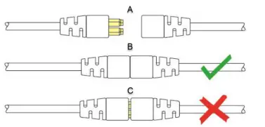
| A | not connected |
| B | correctly connected |
| C | incorrectly connected |
To disconnect the communication cables, firmly hold the connector housing and pull the connectors apart.
NOTE: Pull the connector apart in a straight line to not damage the connection pins.
R-net parameters
Some R-net parameters need to be set for correct usage of the mo-vis R-net joysticks. For this we refer to the Curtiss-Wright manual SK77981-14 | R-net Technical Manual | Chapter 3 – Programming
R-net (Ch. 3 – 4.4):Profile Management > Input Device Type:
- In most cases, this parameter needs to be set to Universal for all mo-vis joysticks.
- In combination with certain other devices (e.g. Scoot Control), it is advised to set this parameter to JSM. Please refer to the Installation manual of the other devices for more information.
NOTE: If you have several input devices of the same type, please refer to the Curtiss-Wright manual SK77981-14 | R-net Technical Manual | Chapter 3 – Programming to install as Input Device Subtype. R-net (Ch. 3 – 7.5): Controls > Global > Profile Button: the default setting of this parameter is Profiles. If you want access to the modes for control of other wheelchair functionalities, such as seating positions, etc., then you have to select Profiles/Modes.
LED status
The illumination of the LED on the joystick interface indicates the operational status of the joystick.
| R-NET STATUS | TILT PARAMETER | JOYSTICK TILTED | LED STATUS |
| Out of focus | X | X | LED flashes as heartbeat |
| In focus | Enabled | N | LED on |
| In focus | Enabled | Y | LED flashes as heartbeat |
| In focus | Disabled | Y | LED on |
| In focus | Disabled | N | LED on |
| Configuring | X | X | LED flashes fast |
| Power cycle | X | X | LED flashes as heartbeat |
| Error | X | X | Flash the error code |
When a fault occurs, the LED of the mo-vis Joystick will start to flash. A long delay is followed by a number of flashes with a short delay. The error message depends on the connection type. Count the number of flashes and look up the according error message in the table below:
| FLASH COUNT | REASON | REQUIRED ACTION |
| 1 | – | – |
| 2 | Connection cable/dri- ver issues | Check/replace cable to wheel- chair, and / or check / replace sensor cable (if available), or replace PCB |
| 3 | Power supply | Check cable and/or replace PCB |
| 4 | Joystick/sensor fault | Check/replace joystick |
| 5 | – | – |
| 6 | ADC – internal Analog to Digital converter | Replace PCB |
| 7 | Test flag failed or Diag- nostic failed | Redo tests and/or replace PCB |
| 8 | CPU fault | Replace PCB |
| FLASH COUNT | REASON | REQUIRED ACTION |
| 9 | Scheduler fault | Update software or replace PCB |
| 10 | Coding error | Update software or replace PCB |
R-net trip codes
TROUBLE:
When a fault is detected by the device, an R-net trip code will be generated. The trip code will be shown on the joystick (if it is present and equipped with a graphic display). The trip code will also be logged in the R-net system and can be investigated using the R-net PC Programmer. If you want to learn more about trip codes, see the Curtiss-Wright manual | SK77981-14 R-net Technical Manual.
Fault log
TROUBLE:
A fault log with counters is maintained. The fault log can be accessed by the configurator (dealer level). Below is an overview of registered faults.
| FAULT | REASON | REQUIRED ACTION |
| CPU error RAM | CPU consistency check failed | Replace PCB |
| CPU error FLASH | ||
| CPU error EEPROM | ||
| Run error scheduler | Firmware consistency check failed | Update Software or replace PCB |
| Code error framework | ||
| Code error application | ||
| MSP command corrupt | Corrupt command was received | Connection with the PC went wrong, try again |
| FAULT | REASON | REQUIRED ACTION |
| MSP command unknown | Unknown command was received | Connection with the PC went wrong. Update firmware (contact mo- vis) or update the Con- figurator Software. Try again. |
| MSP sub command unknown | Unknown sub com- mand was received | |
| MSP argument invalid | Invalid argument received | |
| MSP device not ready | Device was not ready to receive an MSP com- mand | Connection with the PC went wrong. Update firmware (contact mo- vis) or update the Con- figurator Software. Try again. |
| MSP device wrong state | The device is not able to receive a command in the current device | |
| PCB test failed | Factory test failed | Contact mo-vis |
| Assembly test failed | ||
| Field test failed | Field test failed (cali- bration) | |
| Test flag check | One or more test flags not set | Redo tests and/or con- tact mo-vis |
| FAULT | REASON | REQUIRED ACTION |
| ADC | ADC conversion error | Check R-net cable, replace PCB interface |
| FAULT | REASON | REQUIRED ACTION |
| R-net Uart overflow | Uart send queue is full | Replace PCB |
| R-net Uart Underflow | Uart receive queue is empty | |
| R-net Communication timeout | Maximum number of packet retransmissions is reached | Replace PCB |
| R-net Tx overflow | Packet transmit buffer is full | |
| R-net Rx overflow | Packet receive buffer is full | Replace PCB |
| R-net invalid seq nr | Received a packet with an invalid sequence number | |
| R-net data packet error | Data packet ACK mis- match | Replace PCB |
| R-net data descr error | Invalid packet data descriptor |
| FAULT | REASON | REQUIRED ACTION |
| R-net Api version error | The R-net chip contains an invalid API version | Load the latest API version into the R-net chipset with the R-net dongle |
| R-net chip tripped error | The R-net chipset has encountered an inter- nal error | Internal chipset error: Replace PCB R-net system error: solve R-net system error |
| Communication | Communication with the sensor (joystick) failed | Check cable to sensor and/or replace sensor (only authorized deal- ers) or contact mo-vis |
| Sensor (joystick) | The sensor (joystick) is faulty | |
| Accelerometer | The accelerometer fails | Replace PCB interface |
Supported R-net parameters
The following R-net parameters of the wheelchair electronics may or may not be supported by the mo-vis joysticks.
| PARAMETER | SUPPORTED | FIRMWARE VERSION |
| Momentary screens enabled | N | |
| Change profile while dri- ving | N | |
| Change speed while dri- ving | N | |
| Actuator switches while driving | N | |
| Speed adjust | N | |
| Profile button | Y | V02.00 |
| Actuator endstop beep | N | |
| Sounder volume | Y | V02.03 |
| Start-up beep | N | |
| Lock function enabled | N | |
| Reverse driving alarm | Y | V02.00 |
| PARAMETER | SUPPORTED | FIRMWARE VERSION |
| Emergency stop switch | N | |
| OBP keycode entry | N | |
| Power-up mode | N | |
| External profile jack func- tion | N | |
| Profile / mode jack detect | N | |
| On / off jack detect | N |
| Joystick forward throw | Y | V02.01 |
| Joystick reverse throw | Y | V02.01 |
| Joystick left throw | Y | V02.01 |
| Joystick right throw | Y | V02.01 |
| PARAMETER | SUPPORTED | FIRMWARE VERSION |
| Joystick deadband | N
NOTE: Use dead band setting in the mo-vis configurator | |
| Invert left/right JS axis | Y | V02.01 |
| Invert fw/rev JS axis | Y | V02.01 |
| Swap joystick axis | N
NOTE: Use rotate function in the mo- vis configurator | |
| Change mode while dri- ving | Y | V02.00 |
| Sleep timer | Y | V02.00 |
| Standby timer | Y | V02.00 |
| Switch to standby | Y | V02.01 |
| Mode selection in standby | Y | V02.01 |
| PARAMETER | SUPPORTED | FIRMWARE VERSION |
| Standby in modes | Y | V02.01 |
| Standby forward | Y | V02.00 |
| Standby reverse | Y | V02.00 |
| Standby left | Y | V02.00 |
| Standby right | Y | V02.00 |
| Remote selection | Y | V02.03 |
| Background | N |
Technical data
Product description & code
- P002-51 Micro Joystick Omni
- P002-52 Micro Joystick R-net
Interface connectors
- 3.5 mm mono jack on/off
- 3.5 mm mono jack in mode
- mini USB
- connector cable, depending on the joystick version (see Omni Joystick Connection on page 30 or R-net Joystick Connection on page 37 for more information)
Dimensions
Required force
Required force: ca. 8 gr (0.28 oz)
mo-vis bv . Biebuyckstraat 15D. 9850 Deinze – Belgium
www.mo-vis.com. [email protected]. +32 9 335 28 60
Go to our website for more information on our products or share your experience with us via email.


