![]()
All manuals and user guides at all-guides.com
Instruction manual
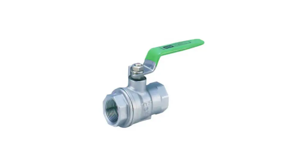
MAX SERIES Ball Valve BR BS VR TR LR T3 L3
OSYBR20A-EN
SP-1408
Please read this manual before installation and use.
GENERAL
This series is suitable for main or bypass valve in piping system.
The position of manual handle can be changed.
Manual operation
Valve only
Lever
Gear
Valve
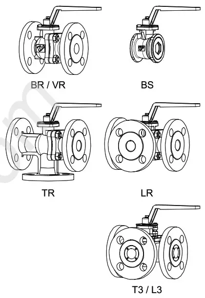
BR type For various fluids and general use.
BS type For Wafer.
TR / LR type For mixing / dividing.
T3 type Trunnion structure. (with flow paths)
L3 type Trunnion structure.
PRODUCT CODE
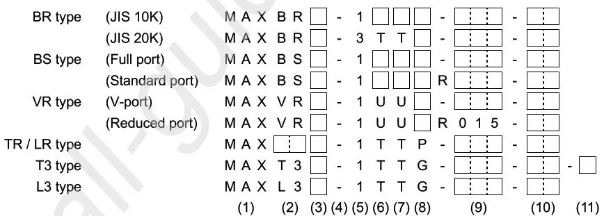
| (1) Actuator MAX (2) Valve BR BS VR TR LR T3 L3 (3) Operation 0 : (Zero) Valve only L : With manual lever G : Gear (4) Sizing code – : Hyphen (5) Connection 1 : JIS 10K 3 : JIS 20K | (6) Body material T : SCS13A U : SCS14A (7) Ball material T : SUS304 / SCS13A U : SUS316 / SCS14A (8) Seat material F : F-PTFE G : R-PTFE R : R-F-PTFE P : R-PTFE (9) Size [mm] ex. 25 A 025 (10) Option ST : Seat for abnormal pressure rise (11) Flow paths a to d : T3 type |
VALVES SPECIFICATIONS
![]() Water
Water ![]() Oil
Oil ![]() Air,
Air, ![]() Gas Steam
Gas Steam ![]() Chemicals
Chemicals ![]() Sea water
Sea water ![]() Slurry
Slurry ![]() Negative pressure
Negative pressure
BR BS VR type
| Valve type | BR | BS | VR | ||||
| Design | 2-way, Full port | 2-way, Wafer | 2-way, V-port | ||||
| Connection | JIS1OK Flanged-end | JIS2OK Flanged-end | JIS Flanges 10K | JIS1OK Flanged-end | |||
| Fluid | |||||||
| Max pressure | 1 MPa | 2 MPa | 1 MPa | 1 MPa | |||
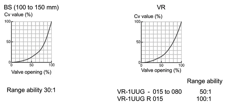
| Size [mm] | 015 to 100 | 015 to 150 | 015 to 080 | 015 to 150 | 015 to 080 | ||
| Material | Body | SCS14A | SCS13A | SCS13A | SCS13A | SCS14A | SCS14A |
| Ball | SCS14A | SCS13A | SCS13A | SCS13A | SCS14A | SUS316 / SCS14A | |
| Seat | F-PTFE R-PTFE R-F-PTFE | F-PTFE R-PTFE R-F-PTFE | R-PTFE R-F-PTFE | ||||
| Stem seal | Packing | R-PTFE | R-PTFE | R-PTFE | |||
| 0-ring | FKM | FKM | FKM | ||||
The optional for steam fluids.
| Valve type | Option code | 0-ring |
| BR BS VR | ST | Replace (Steam resistant FKM) |
PRESSURE & TEMPERATURE RATING
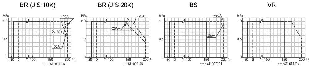
Note) Insulation options are required for use with fluids more than 150 °C.
INHERENT FLOW CHARACTERISTIC
![]() Water
Water ![]() Oil
Oil ![]() Air,
Air, ![]() Gas Steam
Gas Steam ![]() Chemicals
Chemicals ![]() Sea water
Sea water ![]() Slurry
Slurry ![]() Negative pressure
Negative pressure
TR LR T3 L3 type
| Valve type | TR / LR | T3 / L3 | ||
| Design | 3-way, Full port | 3-way, Full port | ||
| Connection | JIS1OK Flanged-end | JIS1OK Flanged-end | ||
| Fluid | ||||
| Max pressure | 1 MPa | 1 MPa | ||
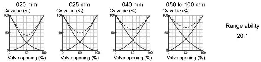
| Size [mm] | 020 to 040 | 050 to 100 | 025 to 150 | |
| Material | Body | SCS13A | SCS13A | |
| Ball | SUS304 | SCS13A | SCS13A | |
| Seat | R-PTFE | R-PTFE | ||
| Stem seal | Packing | R-PTFE | PTFE | |
| 0-ring | FKM | – | ||
The optional for steam fluids.
| Valve type | Option code | 0-ring |
| TR LR | ST | Replace |
| T3 L3 | ST-VF | Add |
O-ring: Steam resistant FKM
PRESSURE & TEMPERATURE RATING
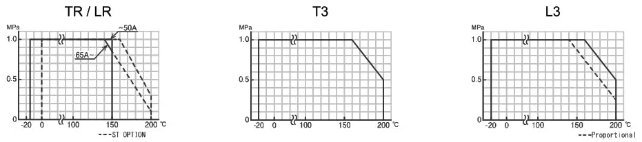
Note) Insulation options are required for use with fluids more than 150 °C. (T3 / L3: 170 °C)
INHERENT FLOW CHARACTERISTIC (TR / LR)
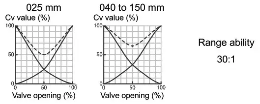
INHERENT FLOW CHARACTERISTIC (L3)
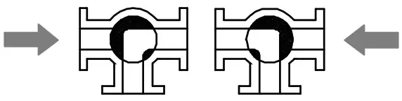
FLOW PATHS (Position 1 / P1) (Position 2 / P2)
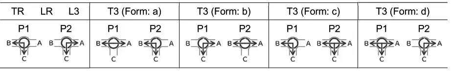
Note) When a closed path is exposed to high pressure, it may leak slightly to an open path. (TR / LR)
INSTALLATION, OPERATION & MAINTENANCE INSTRUCTIONS
LEVER AND GEAR DIMENSIONS
1 CASTING LEVER
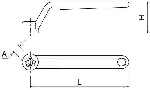
| Valve size [mm] | Lever | Hex bolt | ||||
| BS | BR VR TR LR L3 | T3 | L | H | A | |
| 015 to 020 | 015 to 020 | – | 115 | 36 | 9 | M5×15 |
| 025 to 032 | 025 to 032 | 025 | 145 | 46 | 11 | M5x15 |
| 040 to 050 | 040 to 050 | 040 | 220 | 52 | 14 | M6×15 |
| 065 to 100 | 065 to 080 | 050 to 065 | 320 | 55 | 17 | M8×15 |
| 125 to 150 | 100 to 125 | 080 to 100 | 430 | 60 | 22 | M10×20 |
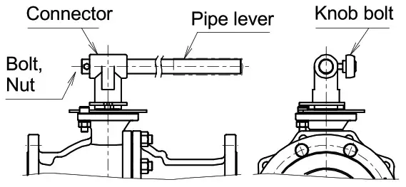
2 PIPE LEVER
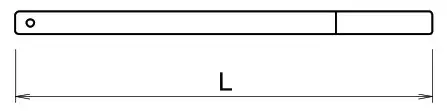
| Valve size [mm] | Lever | Knob bolt | |
| BR L3 | T3 | L | |
| 150 | 125 to 150 | 750 | M10x25 |
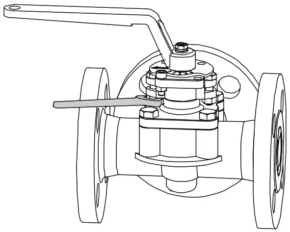
HANDLING OF MANUAL LEVER
- Attention
• The lever handle is removed and shipped.
• The lever mounting direction can be changed in units of 45 degrees.
• Do not apply excessive torque to the lever.
• Do not strike or extend the lever with a tool.
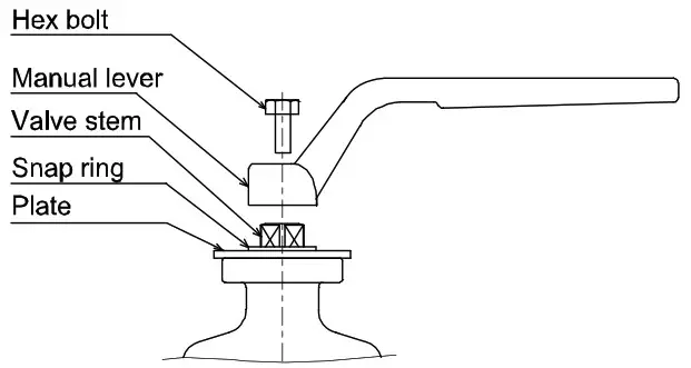
• The arrow on the plate indicates the direction of flow. - LEVER HANDLE INSTALLATION (Casting lever)
• Plate of position indicator is attached on the valve by C-type snap ring. Install the manual lever on it tightening the bolt.
• The position of manual lever can be changed according to piping circumstances.
- LEVER HANDLE INSTALLATION (Pipe lever)
• Remove the bolt and nut from the lever.
• Loosen the knob bolt. Insert the lever into the connector.
• Tighten the bolts so that the lever does not fall off.
• Fix the lever with the knob bolt.
GEAR DIMENSIONS
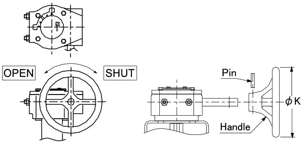
| Valve size [mm] | K | Actuator | ||
| BS | BR VR TR LR L3 | T3 | ||
| 065 | 065 | 050 | Φ150 | MAG-F07 |
| to | to | to | ||
| 100 | 080 | 065 | ||
| 125 | 100 | 080 | Φ300 | MAG-F10 |
| to | to | to | ||
| 150 | 125 | 100 | ||
| – | 150 | 125 to 150 | Φ300 | MAG-F12 |
HANDLING OF GEAR
- The handle wheel of the gear is removed and shipped.
- Insert the handle into the gear shaft.
- Insert a pin into the hole in the handle.
HANDLING & STORAGE
- HANDLING
Proper care in handling the valve should be taken to prevent damage. Do not drop or throw it. - STORAGE
Store the valve in the protected area from dust, moisture, and direct sunlight. If possible, should be kept in the original packaging. - CHECKING
• Check the product code before installation.
• Confirm that there is no screw loose or part deformation.
INSTALLATION
- PRECAUTIONS
Before installing, clean pipe and valve ends.
Make sure they are free of dirt, dust and etc. - PIPING FLANGES
• VR type has a flow direction. Install the valve accordingly.
• Specify the ST option if a steam fluid. Flow direction is restricted by ST option. (BR / BS)
• Gasket should be selected appropriately to suit the fluid, pressure and temperature.
Use spring washer to prevent from decreasing surface pressure gasket when the temperature change happens frequently.
• Tighten all bolts using crossover method to load the joint evenly.
• Wafer type ball valve is put between two seats of flanged-end and tightened with long bolts. (BS)
• In the TR / LR type, when the flow path is subjected to a high pressure from arrow, it may leak slightly to the low pressure port.
- ENVIRONMENT
If there is a possibility that the fluid and drive part freeze, please take measures to prevent freezing. - POSITIONING
Should be positioned through 90° upward from horizontal. Provide space around the product to allow manual operation, inspection and replacement work. - CAUTIONS FOR MAINTENANCE (T3 / L3)
Do not keep warm for maintenance of the valve gland.
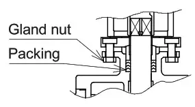
TIGHTEN THE GLAND NUTS (T3 / L3)
- Check that there is no leakage from the gland packing.
- If it leakage, tighten gland nuts by alternately.
Do not over-tighten the gland nuts.
| Recommended torques [N• m] | ||
| Valve size [mm] | Torque | |
| T3 | L3 | |
| 25 | 025 | 3.5 |
| 40 | 040 to 050 | 7 |
| 050 to 065 | 065 to 080 | 10 |
| 080 to 100 | 100 to 125 | 14 |
| 125 to 150 | 150 | 20 |
MAINTENANCE
Do the routine maintenance at least once in half a year.
Inspection items
- Confirm operation of opening and closing.
- Confirm whether screws are loose or not.
- Confirm the fluid temperature or pressure.
- Confirm the leak from valve stem.
- Confirm the bolt tightening torque.
TROUBLESHOOTING
| Problem | Cause | Solution |
| Stop in the mid position. | • Biting of valve seat. • The scale has adhered to the valve ball. | Remove a foreign object. |
| Leakage from valve body | • Valve cap get loose. • Valve body is damaged. | Replace the valve. |
| Leakage from valve seat | Seat is worn or damaged. | Replace the valve. Replace the seat. |
| Leakage from valve stem | Stem packing is worn or distorted. | Replace the valve. Replace the packing. |
| Leakage from valve gland (T3 / L3) | Gland packing is worn or distorted. | Tighten the gland nut. |
| Replace the gland packing. |
For more information contact
NIPPON VALVE CONTROLS, INC. for consultation.
![]()
Document is subject to change without notice.
1-21-19 Meieki minami, Nakamura-ku, Nagoya 450-0003 JAPAN
TEL: 81-52-582-6435 FAX: 81-52-582-6439


