
WATTS BT-WR02 Wireless Wall Receiver
Presentation
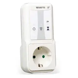
The BT-WR02 H&C RF receiver is a Wall mounting receiver, specially designed to control hydraulic heating regulation or cooling regulation.
It embeds a proportional regulation with a time cycle of 10mn and an Hysteresis regulation: The heating relay is used to control a boiler in free contact or a valve or an electric radiator in live contact. (Available with all thermostats of the BT-x02 BT-x03 range)
The cooling relay is used to manage an actuator for a cold water circuit. (Not available with BT-A02 RF thermostats) 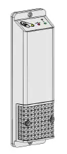
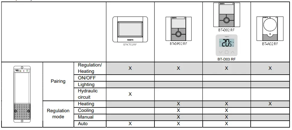
This couple (thermostat BT-x02 or BT-x03 and receiver BT-WR02 H&C RF) can also be managed by a Central unit BT-CT02 RF to have full control of your heating installation from one point. In that case, the receiver works always in the automatic regulation mode for the heating/cooling switch. With the central unit, it is possible to pair the receiver in “Regulation/heating” mode and in “Hydraulic circuit” mode. It is not possible to pair the receiver in lighting mode or ON/OFF mode. You can access to the general leaflet of the system on wastewater.eu.With a BT-D02 RF / BT-D03 RF and BT-DP02 RF it is possible to configure the receiver in manual mode, heating mode, cooling mode or automatic mode (Please refer to the BT-Dx02 RF leaflets).
In all cases, the receiver is making cooling only in comfort mode. All other modes (Reduced, anti-freeze, auto in Reduced) forbid the cooling regulation.
In the case of setpoint modification, a delay of 5mn is always applied before switching from cooling to heating or heating to cooling. In automatic regulation, a dead band of ± 1°K with a timer is applied before switching from heating to cooling or from cooling to heating.
Compatibility matrix:
The receiver is delivered with 2 outputs in free contact mode. To trigger the outputs in live contact, linked the live on 1 point of each connector using the cable supplied in the box.
Display description :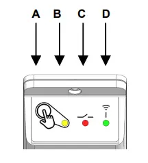
| A (Bouton poussoir) | B (Rouge/Vert) | C (Rouge/Bleu) | D (Orange) | |
| / | / | / | / | Mode OFF |
| Appui court | / | / | / | Mise en ON/OFF avec bip sonore |
| / | Vert fixe | / | / | Confort avec les 2 sorties ouvertes (sans chauffe, sans froid) |
| / | Vert 50% | / | / | Mode Eco avec les 2 sorties ouvertes (sans chauffe, sans froid) |
| / | Vert 10% | / | / | Mode Hors gel avec les 2 sorties ouvertes (sans chauffe, sans froid) |
| / | / | Rouge | / | Chauffe (Sortie Chaud fermée) |
| / | / | Bleu | / | Froid (Sortie Froid fermée) |
| Appui de 10 sec | / | / | Orange clignotant lent | Appairage RF avec un thermostat ou une unité centrale |
| / | / | / | Orange clignotant rapide | Réception RF |
| / | / | / | Orange clignotant rapide permanant | Perte RF |
| / | Clignotant rouge/vert | / | / | Erreur sonde thermostat |
| Appui de 30s | Orange | Bleu/rouge | Orange | Réinitialisation du récepteur |
Technical characteristics
| Environnement. (Températures) Fonctionnement : Transport et stockage : | 0°C – 40°C -10°C à +50°C | ||
| Alimentation | 230Vac 50Hz | ||
| Protection électrique | Classe II | – | IP20 |
| Sortie Charge maximale | Relais 5Amps 250VAC Jusqu’à 5A résistif – 250Vac 50Hz (2 fils L,N) | ||
| Radio Fréquence & Distance de réception | 868MHz < 10mW (communication bidirectionnelle) Environ 100m en milieu ouvert Environ 30m in environnement résidentiel | ||
| Directives CE Votre produit a été conçu en conformité avec les directives européennes : | RED 2014/53/EU LVD 2014/35/EU EMC 2014/30/EU ROHS 2017/2102/EU | ||
| Produit conforme à : | Règlement Européen : N°811/2013 complétant la directive 2010/30/UE concernant l’étiquetage des produits. | ||
| Classification : | IV | ||
| Contribution : | (2%) | ||
| Caractéristiques de régulation | Régulation proportionnelle intégrale ou régulation hystérésis. La régulation est définie par le thermostat lié à la zone (se reporter à la notice du thermostat) | ||
Installation and RF pairing rules
Install and plug the receiver into the following guidelines to guarantee an optimal reception:
- The receiver must be put at a minimum distance of 50cm from all other electrical or wireless materials like GSM, a Wi-Fi routers.
- Before wiring work related to the receiver must be carried out only when de-energized
- Connect your receiver to the power supply.
Following your installation, an order of pairing must be respected for a correct RF initialization.
Installation 1: Receiver BT-WR02 H&C RF + RF thermostat BT-x02
- The receiver must be put in RF pairing mode by 10sec pressing on the button.
- The RF LED should be orange slow flashing, indicating that the Receiver is now in radio configuration mode waiting for a thermostat configuration address.
- Please refer to the thermostat leaflet for entering the thermostat in RF pairing mode
- The receiver RF LED must be switched OFF and the thermostat should exit the RF init mode to indicate the correct pairing between both elements.
Installation 2: Receiver BT-WR02 H&C RF + RF Thermostat BT-x02+ central unit BT-CT02 RF
- Link first the thermostat with the smart home
- The receiver must be put one time more in RF pairing mode by 10 sec pressing on the button.
- Then the RF LED should be orange slow flashing, indicating that the receiver is now in radio pairing mode waiting for a thermostat configuration address.
- Please refer to the Central leaflet for more explanation about the pairing mode “RF Init”. Pair only in heating mode or hydraulic circuit mode
- The receiver RF LED must be switched OFF and the Central will show a message to indicate the correct pairing between both elements
Remarks: – In case of loss RF communication (RF Alarm), the receiver will stop heating or cooling.


