flex7 Lighting Connection & Control App
ABOUT
When you choose products from flex7 you can be certain that you’ve opted for a system that offers unrivaled flexibility combined with the simplest of installation methods.
The following pages detail a number of common lighting control applications ranging from traditional mains rated (on/off) switching through to daylight linking, along with a list of the flex7 products required to achieve each. The scenarios may be diverse, but the only on-site termination required in all cases is LNE to the Distribution Box, so standardizing the installation process regardless of complexity. This is possible because at the heart of every flex7 product is the fundamental of plug-in modularity which, as well as reducing installation time, also offers a trouble-free upgrade path should requirements change in the future; unplug the old device(s) and plug in the new.
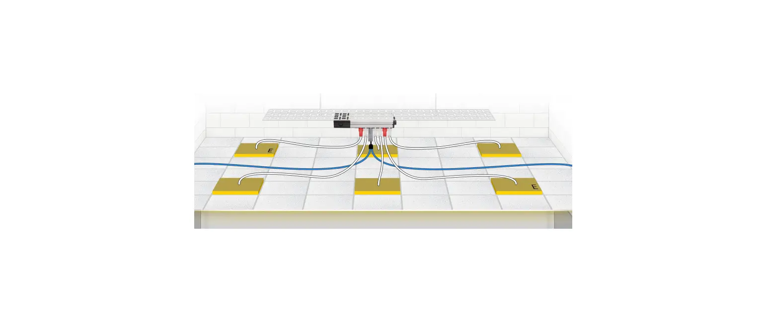
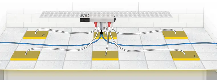
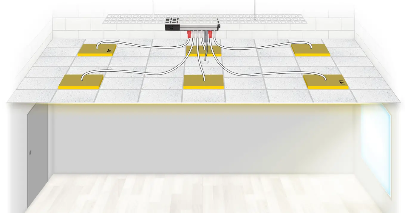
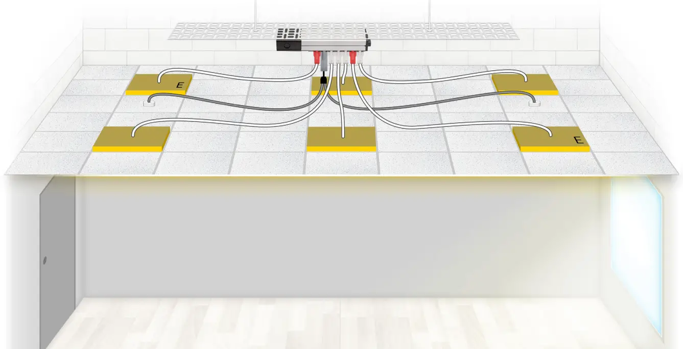
Wiring Connection when using flex7 control
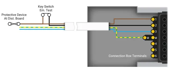
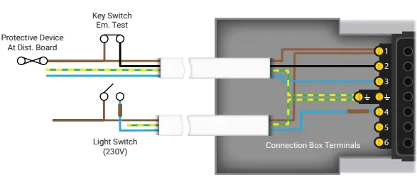
Wiring Connection when using hard-wired control
If the application you’re looking for doesn’t appear in the following pages please contact us on 020 8580 1066. Our Technical team will be able to advise as to the most appropriate products to use in order to achieve the result you need.
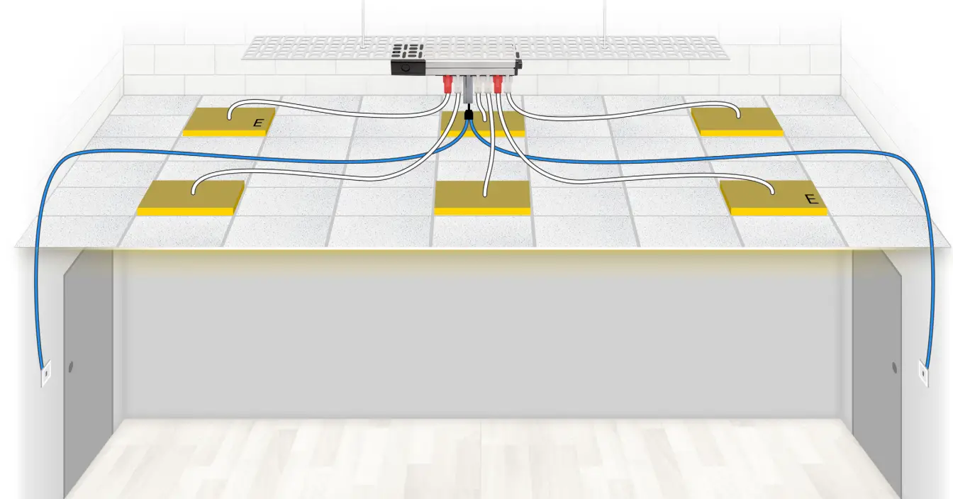
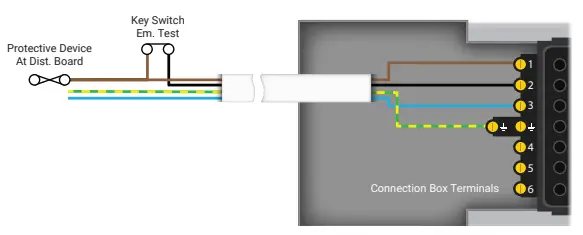
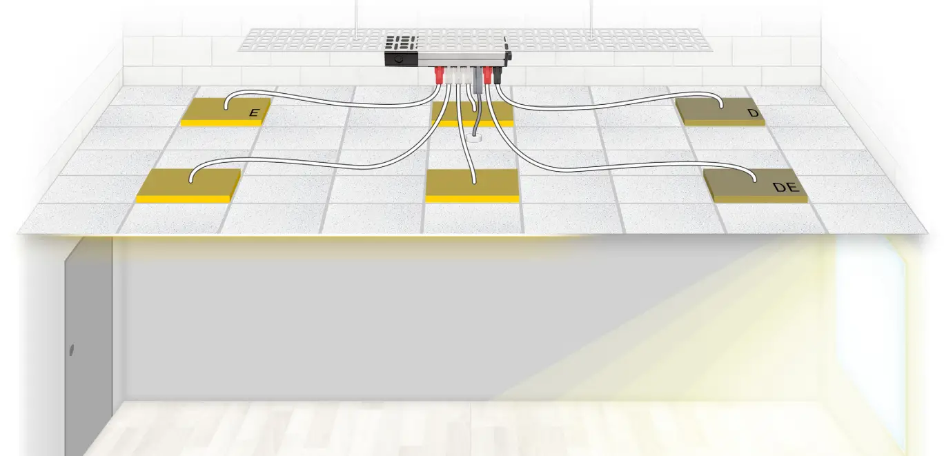
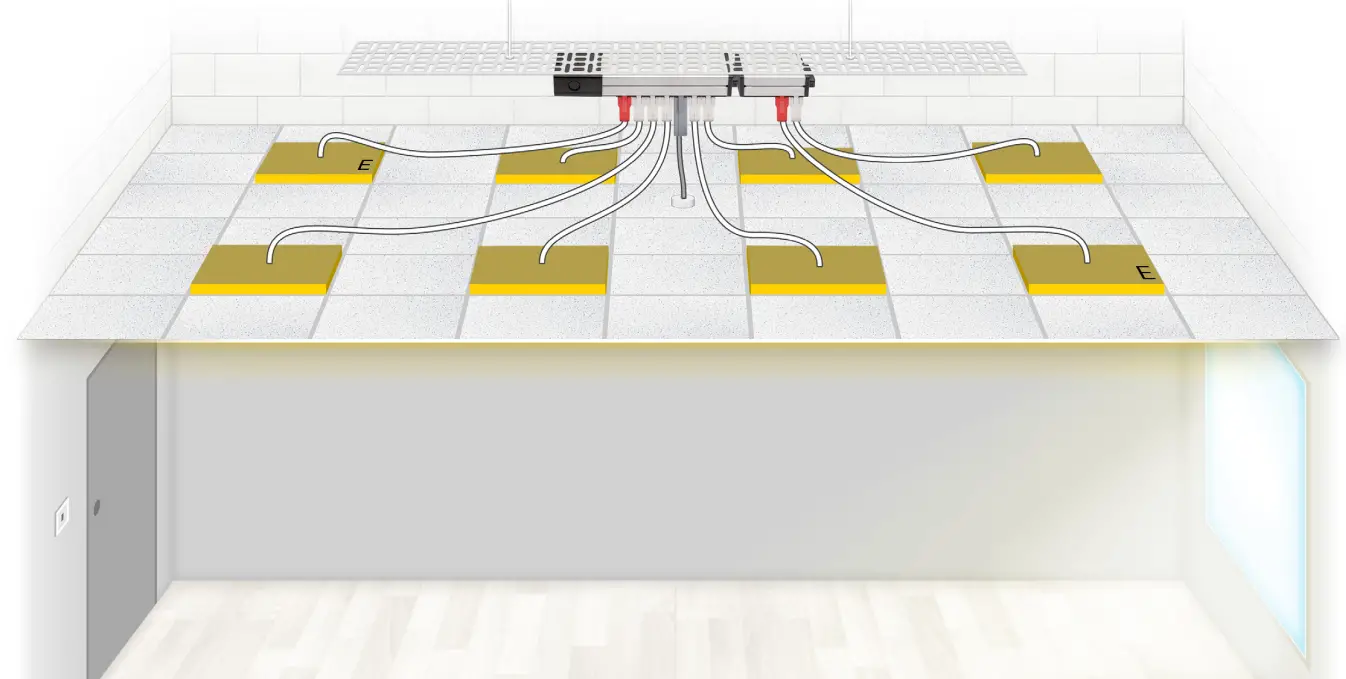
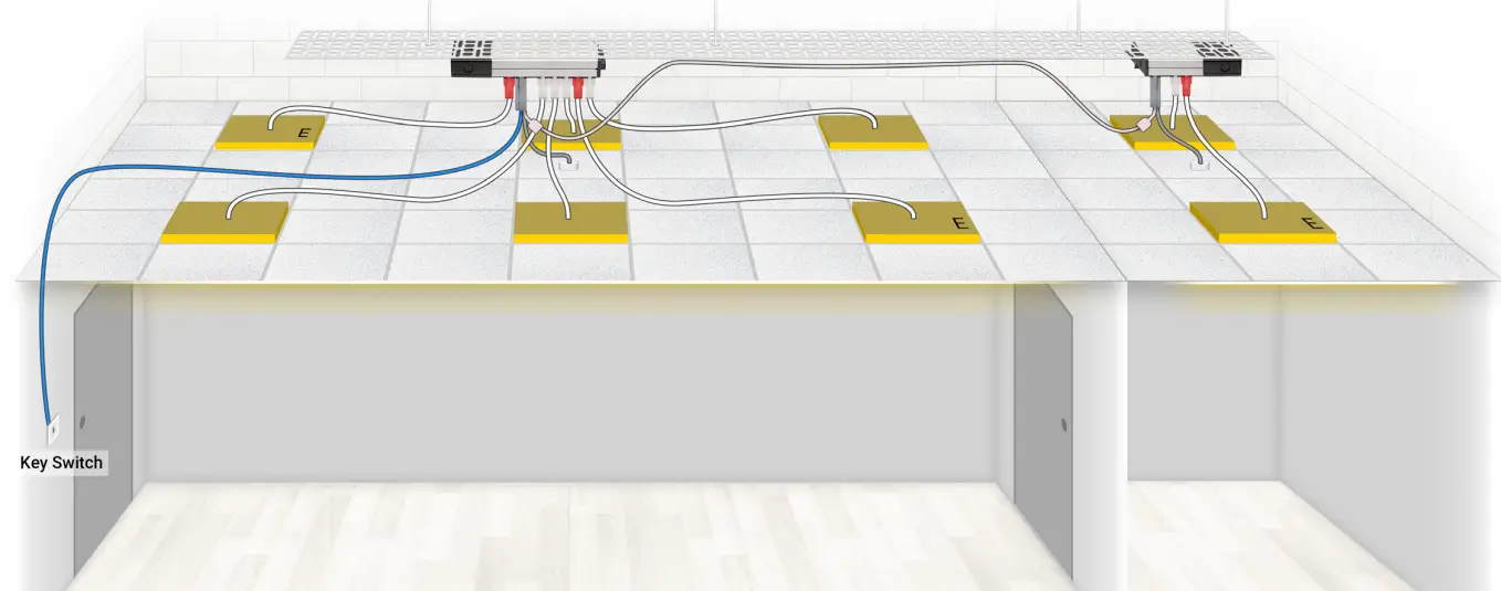
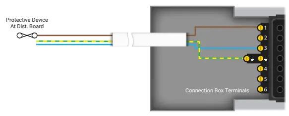
Mains (230V) Switching
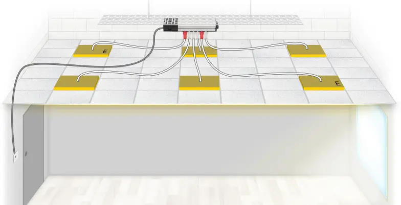
Control of the luminaires is from 1 location via a traditionally hard-wired 230V, 1-way switch; a small range of 230V plug-in switch drops are available if preferred. On-site termination of the supply and 230V control wiring is made as detailed, at the Distribution Box.
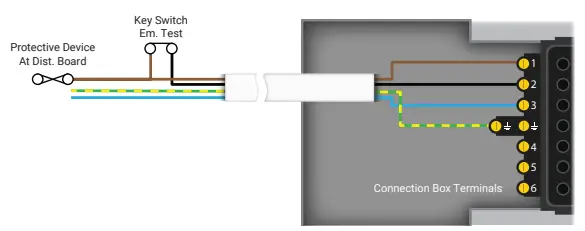
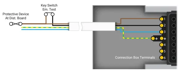
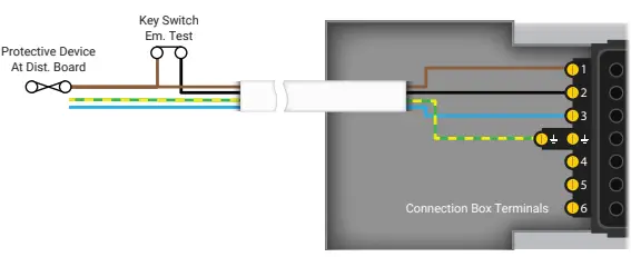
Note: emergency luminaires are tested via a hard-wired 230V key switch, often located in close proximity to the distribution board.
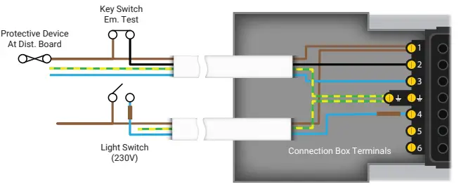
Wiring Connection
| DESCRIPTION | PART NO. |
| 1 X Starter Box | FSU08 |
| 4 X Standard (on/off)Luminaire Lead | FL3100LSHF5/W |
| 2 X Maintained Emergency Luminaire Lead | FL4100LSHF5/R |
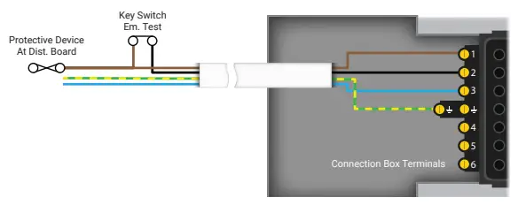
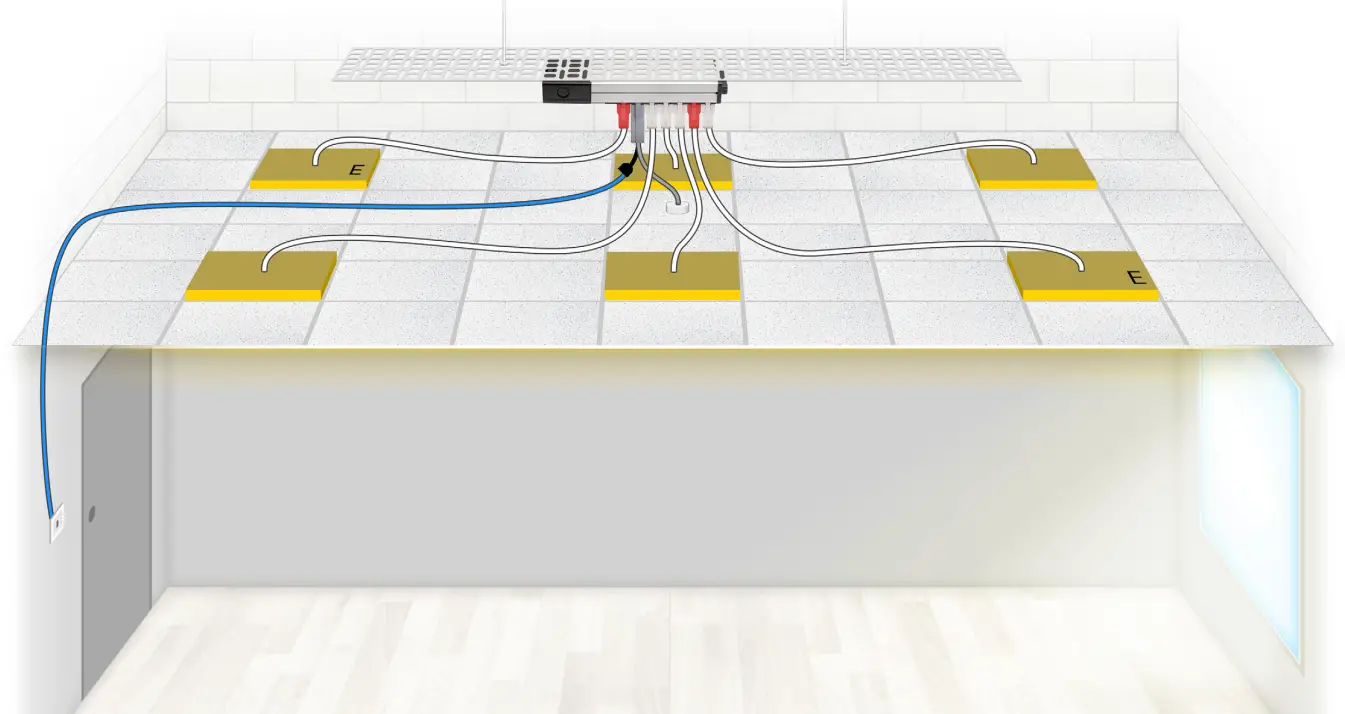
Protected Extra Low Voltage (PELV) Switching
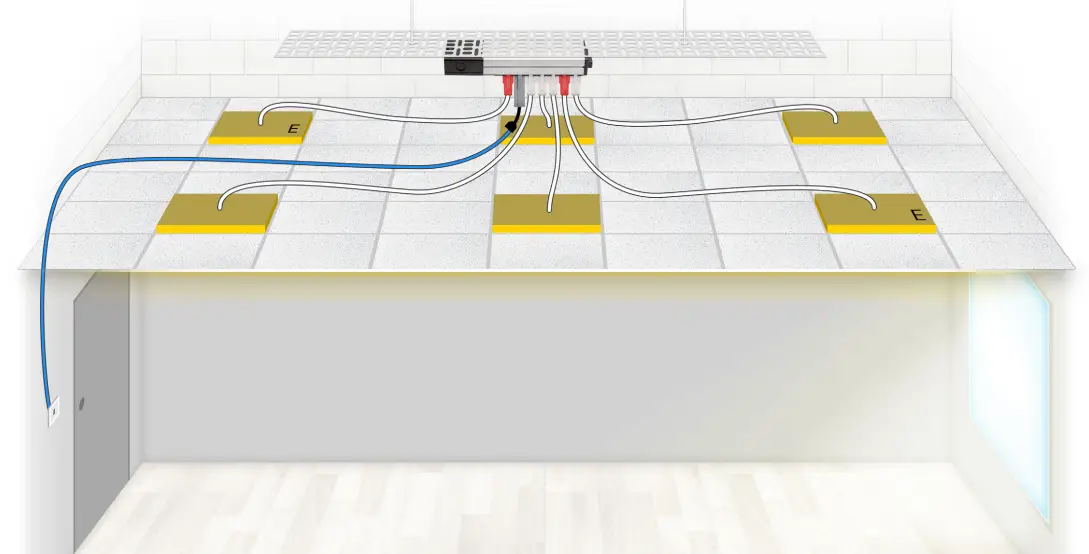
Control of the luminaires is from 1 location via a flex7 plug-in switch operating at PELV. The luminaires are manually switched on or off with a short pulse of the switch. The use of flex7 control modules negate the need for RCD and/or earthed mechanical protection of the switch drop. Additionally, installation time is dramatically reduced as everything plugs-in, meaning only the 4 conductors at the Distribution Box require on-site termination.
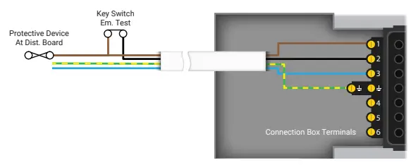
Note: emergency luminaires are tested via a hard-wired 230V key switch, often located in close proximity to the distribution board.
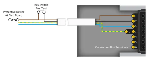
Wiring Connection
| DESCRIPTION | PART NO. |
| 1 X Starter Box | FSU08 |
| 1 X Switch Kit | FNS1000/U |
| 1 X Switch | FWS01/K/AT/W/WP |
| 1 X Switch Adaptor | FWSY/13/AT |
| 4 X Standard (on/off) Luminaire Lead | FL3100LSHF5/W |
| 2 X Maintained Emergency Luminaire Lead | FL4100LSHF5/R |
Protected Extra Low Voltage (PELV) 2-Way Switching
Control of the luminaires is from 2 locations via flex7 plug-in switches operating at PELV. The luminaires are manually switched on or off with a short pulse of either of the switches. The use of flex7 control modules negates the need for RCD and/or earthed mechanical protection of the switch drop. The installation of strappers, usually required for 2-way / intermediate switching, is not necessary. Both switches simply plug into the control module. Additionally, installation time is dramatically reduced as everything plugs in meaning only the 4 conductors at the Distribution Box require on-site termination.
Note: emergency luminaires are tested via a hard-wired 230V key switch, often located in close proximity to the distribution board.
Wiring Connection
| DESCRIPTION | PART NO. |
| 1 X Starter Box | FSU08 |
| 1 X Switch Kit | FNS1000/U |
| 2 X Switch | FWS01/K/AT/W/WP |
| 1 X Switch Adaptor | FWSY/13/AT |
| 1 X Switch Drop Lead | FSL10/BL |
| 4 X Standard (on/off) Luminaire Lead | FL3100LSHF5/W |
| 2 X Maintained Emergency Luminaire Lead | FL4100LSHF5/R |
Protected Extra Low Voltage (PELV) Switching & Manual Dimming
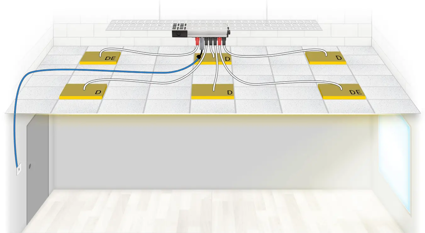
Control of the luminaires, both switching and manual dimming, is from 1 location via a flex7 plug-in switch operating at PELV. The luminaires are manually switched on or off with a short pulse of the switch. Once on, the luminaires can be dimmed or brightened by holding the switch until the desired light level is reached. The use of flex7 control modules negate the need for RCD and/or earthed mechanical protection of the switch drop. Additionally, installation time is dramatically reduced as everything plugs in meaning only the 4 conductors at the Distribution Box require on-site termination.
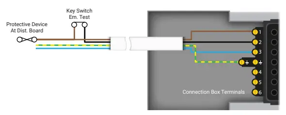
Note: emergency luminaires are tested via a hard-wired 230V key switch, often located in close proximity to the distribution board.
Wiring Connection
| DESCRIPTION | PART NO. |
| 1 X Starter Box | FSU08 |
| 1 X Switch Kit | FNS3000X/U |
| 1 X Switch | FWS01/K/AB/W/WP |
| 1 X Switch Adaptor | FWSY3/AB |
| 4 X Dimming Luminaire Lead | FL5100LSHF5/B |
| 2 X Dimming Maintained Emergency Luminaire Lead | FL6100LSHF5/R |
Protected Extra Low Voltage (PELV) Occupancy Control
Control of the luminaires is via a flex7 plug-in sensor head operating at PELV. The luminaires are automatically switched on when movement is sensed. After the room is vacated the luminaires switch off when the timeout period has elapsed. Installation time is dramatically reduced as everything plugs-in, meaning only the 4 conductors at the Distribution Box require on-site termination.
Note: emergency luminaires are tested via a hard-wired 230V key switch, often located in close proximity to the distribution board.
Wiring Connection
| DESCRIPTION | PART NO. |
| 1 X Starter Box | FSU08 |
| 1 X Sensor Kit | FNS1200 |
| 4 X Standard (on/off) Luminaire Lead | FL3100LSHF5/W |
| 2 X Maintained Emergency Luminaire Lead | FL4100LSHF5/R |
Protected Extra Low Voltage (PELV) Occupany Control (2 x Heads)
Control of the luminaires is via 2 flex7 plug-in sensor heads operating at PELV. The luminaires are automatically switched on when movement is sensed. After the room is vacated the luminaires switch off when the timeout period has elapsed. The decision to install 2 (or more) sensor heads as opposed to 1 may be made simply because the room is too large to be covered effectively by 1. Alternatively, day to day use of the room may be such that occupants will be desk based for long periods meaning fine movements need to be detected to avoid luminaires switching off whilst the room is still occupied. Installation time is dramatically reduced as everything plugs-in, meaning only the 4 conductors at the Distribution Box require on-site termination.
Note: emergency luminaires are tested via a hard-wired 230V key switch, often located in close proximity to the distribution board.
Wiring Connection
| DESCRIPTION PART NO. | |
| 1 X Starter Box FSU08 | |
| 1 X Sensor Kit FNS1200 | |
| 1 X AUX Sensor Head FNH/AUX | |
| 1 X Sensor Lead FSL05 | |
| 4 X Standard (on/off) Luminaire FL3100LSHF5/W Lead | |
| 2 X Maintained Emergency FL4100LSHF5/R Luminaire Lead | |
Protected Extra Low Voltage (PELV) Occupancy & Daylight Linking To Window Luminaires
Control of the luminaires is via a flex7 plug-in sensor head operating at PELV. The 2 luminaires adjacent to the window are dimmable. The luminaires are automatically switched on when movement is sensed. After the room is vacated the luminaires switch off when the timeout period has elapsed. A second layer of control, in the form of daylight linking, is applied to the dimmable luminaires adjacent to the window. As the available natural light increases/decreases during the day, the window luminaires’ light output will also increase/decrease in order to maintain the optimum light level in that area of the room. Installation time is dramatically reduced as everything plugs-in, meaning only the 4 conductors at the Distribution Box require on-site termination.
Note: emergency luminaires are tested via a hard-wired 230V key switch, often located in close proximity to the distribution board.
Wiring Connection
| DESCRIPTION | PART NO. |
| 1 X Starter Box | FSU08 |
| 1 X Sensor Kit | FNS3400X |
| 3 X Standard (on/off) Luminaire Lead | FL3100LSHF5/W |
| 1 X Maintained Emergency Luminaire Lead | FL4100LSHF5/R |
| 1 X Dimming Luminaire Lead | FL5100LSHF5/B |
| 1 X Dimming Maintained Emergency Luminaire Lead | FL6100LSHF5/R |
Protected Extra Low Voltage (PELV) Absence Control
Control of the luminaires is via a flex7 plug-in sensor head and switch, both operating at PELV. The luminaires are manually switched on with a short pulse of the switch, after which they remain on whilst movement is sensed. After the room is vacated the luminaires switch off when the timeout period has elapsed. The use of flex7 control modules negate the need for RCD and/or earthed mechanical protection of the switch drop. Additionally, installation time is dramatically reduced as everything plugs-in, meaning only the 4 conductors at the Distribution Box require on-site termination.
Note: emergency luminaires are tested via a hard-wired 230V key switch, often located in close proximity to the distribution board.
Wiring Connection
| DESCRIPTION | PART NO. |
| 1 X Starter Box | FSU08 |
| 1 X Sensor Kit | FNS1200/U |
| 1 X Switch | FWS01/K/AT/W/WP |
| 1 X Switch Adaptor | FWSY3/AB |
| 4 X Standard (on/off) Luminaire Lead | FL3100LSHF5/W |
| 2 X Maintained Emergency Luminaire Lead | FL4100LSHF5/R |
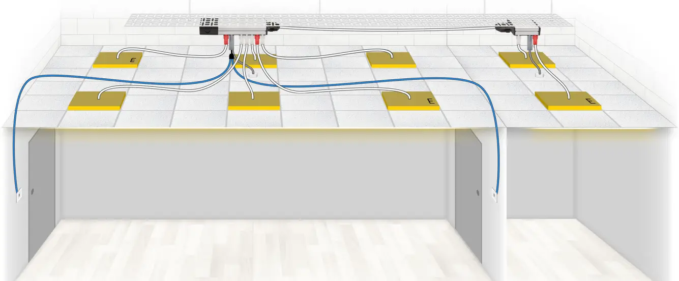
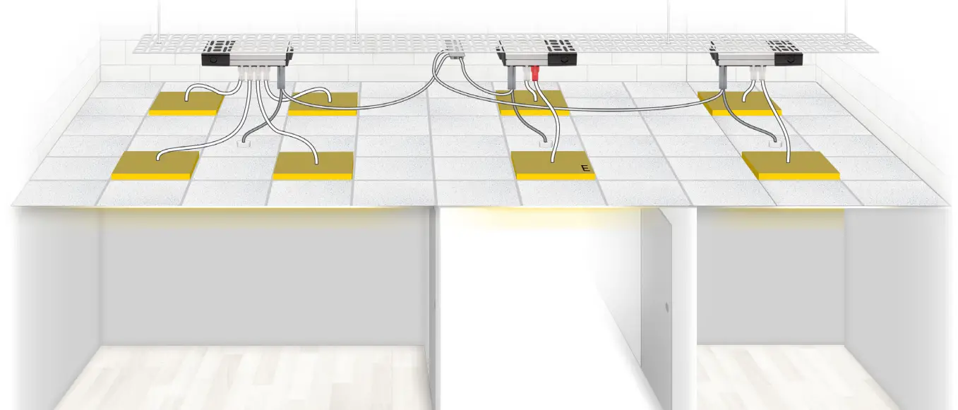
Protected Extra Low Voltage (PELV) Occupancy Control + Expansion Unit For Extra Luminaires
2 of the luminaires have been added at a later date to the original 6, resulting in the Distribution Box being too small for the new layout. A flex7 Expansion Box is plugged directly into the end-cap socket of the original box, instantly increasing the number of available outlets. The 2 boxes now operate as 1. A range of expansion leads are available if the installation would benefit from the 2 boxes being remote from each other. Control of the luminaires is via a flex7 plug-in sensor head operating at PELV. The luminaires are automatically switched on when movement is sensed. After the room is vacated the luminaires switch off when the timeout period has elapsed.
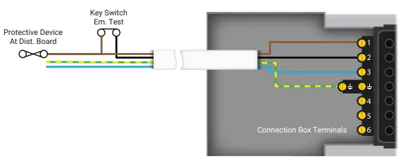
Note: emergency luminaires are tested via a hard-wired 230V key switch, often located in close proximity to the distribution board.
Wiring Connection
| DESCRIPTION | PART NO. |
| 1 X Starter Box | FSU08 |
| 1 X Expansion Unit | FXU04 |
| 1 X Sensor Kit | FNS1200/U |
| 1 X Switch | FWS01/K/AT/W/WP |
| 1 X Switch Adaptor | FWSY/13/AT |
| 6 X Standard (on/off) Luminaire Lead | FL3100LSHF5/W |
| 2 X Maintained Emergency Luminaire Lead | FL4100LSHF5/R |
Protected Extra Low Voltage (PELV) Absence Control + Tap-Off Unit With Protected Extra Low Voltage (PELV) Occupancy Control For Next Room
Originally 1 large office. Reconfigured to create 2 separate spaces, requiring individual control; absence for the Office; occupancy for the Store Cupboard. A flex7 tap-off box is plugged into the original box via a tap-off lead. The boxes now share the same supply, but require separate flex7 control modules. Control of Office luminaires is via a flex7 plug-in sensor head and switches, all operating at PELV. The luminaires are manually switched on with a short pulse of either switch. They remain on whilst movement is sensed. After the room is vacated the luminaires switch off when the timeout period has elapsed. Control of Store Cupboard luminaires is via a flex7 plug-in sensor head operating at PELV. The luminaires are automatically switched on when movement is sensed. After the room is vacated the luminaires switch off when the timeout period, has elapsed.
Note: emergency luminaires are tested via a hard-wired 230V key switch, often located in close proximity to the distribution board.
Wiring Connection
| DESCRIPTION | PART NO. |
| 1 X Starter Box | FSU08 |
| 1 X Tap-Off Unit | FTU04 |
| 1 X Tap-Off Lead | FT4150LSHF5/B |
| 1 X Sensor Kit | FNS1200 |
| 1 X Switch Lead | FWSY3/AB |
| 1 x Switch Drop Lead | FSL10/BL |
| 1 X Sensor Kit | FNS1200/U |
| 2 X Switch | FWS01/K/AT/W/WP |
| 1 X Switch Adaptor | FWSY/13/AT |
| 5 X Standard (On/Off) Luminaire Lead | FL3100LSHF5/W |
| 3 X Maintained Emergency Luminaire Lead | FL4100LSHF5/R |
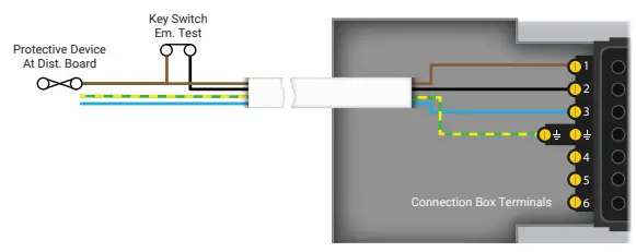
2 x Protected Extra Low Voltage (PELV) Occupancy Control + Global Emergency Test
An Office and adjoining Store Cupboard, each protected by different devices at the distribution board (could be different phases), requiring individual occupancy control, but a single key switch to facilitate emergency test across both circuits. Each space has its own flex7 starter Distribution Box with a separate 3-core supply (LNE) back to the distribution board; no separate emergency live is required. Control of the Office and the Store Cupboard luminaires is via separate flex7 plug-in sensor heads operating at PELV. The luminaires are automatically switched on when movement is sensed. After the room is vacated the luminaires in that room switch off when the timeout period has elapsed. The plug-in switch drop is connected to a latching key switch located next to the office door and operates at PELV. The switch affects the separate emergency relay in both networked control modules, simultaneously initiating the emergency test across both separate circuits.
Note: emergency control modules can be configured so that during a test all connected luminaires are isolated from the supply or only emergency luminaires are isolated leaving non-emergencies fully operational.
Wiring Connection
| DESCRIPTION | PART NO. |
| 1 X Starter Box (8-way) | FSU08 |
| 1 X Starter Box (4 way) | FSU04 |
| 2 X Control Module | FNC2000/E |
| 2 X Sensor Head | FNH200 |
| 2 X Link Lead | FSL05 |
| 1 X Switch Drop Lead | FSW10 |
| 1 X Netwok Lead | FNL05 |
| 2 X Network Adaptor | FNY/Y |
| 5 X Standard (On/Off) Luminaire Lead | FL3100LSHF5/W |
| 3 X Maintained Emergency Luminaire Lead | FL4100LSHF5/R |
3 x Protected Extra Low Voltage (PELV) Occupancy Control + Corridor Hold
Two Offices, either side of a central Corridor, all protected by different devices at the distribution board (could be different phases); all three requiring individual occupancy control. Control of both Offices and Corridor luminaires is via separate flex7 plug-in sensor heads operating at PELV. The luminaires are automatically switched on when movement is sensed. After the room is vacated the luminaires in that room switch off when the time-out period has elapsed. The addition of a plug-in Corridor Hold facility means that the corridor luminaires are held on whilst either of the Offices are occupied. Crucially, movement detected in the corridor has no effect on the Office luminaires.
Note: emergency luminaires are tested via a hard-wired 230V key switch, often located in close proximity to the distribution board.
Wiring Connection
| DESCRIPTION | PART NO. |
| 1 X Starter Box (6-way) | FSU06 |
| 2 X Starter Box (4-way) | FSU04 |
| 3 X Control Module | FNC2000 |
| 3 X Sensor Head | FNH200 |
| 3 X Link Lead | FSL05 |
| 3 X Network Lead | FNL05 |
| 1 X Corridor Hold Unit | FCH8/2 |
| 7 X Standard (On/Off) Luminaire Lead | FL3100LSHF5/W |
| 1 X Maintained Emergency Luminaire Lead | FL4100LSHF5/R |
flex7 Ltd
Ruscombe Business Park Ruscombe Lane
Twyford RG10 9LR
www.flex7.co.uk | [email protected]


