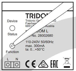
TRIDONIC 28002680 Lighting Controls and Connectivity sceneCOM
Contents hide
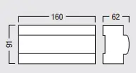
DIMENSION
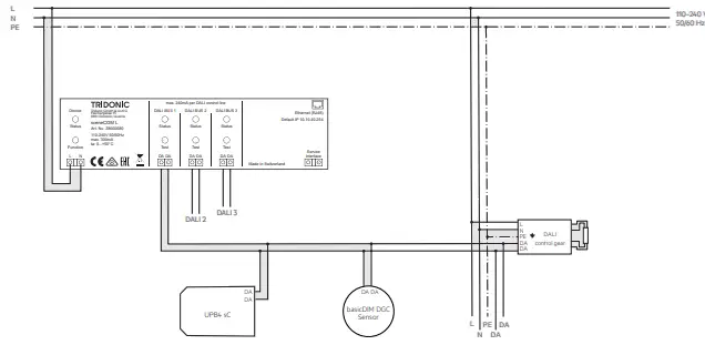
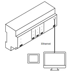
Topology A
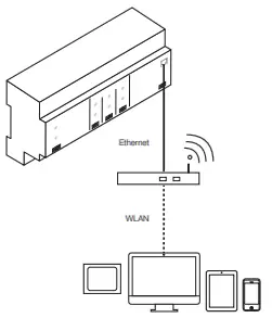
Topology B
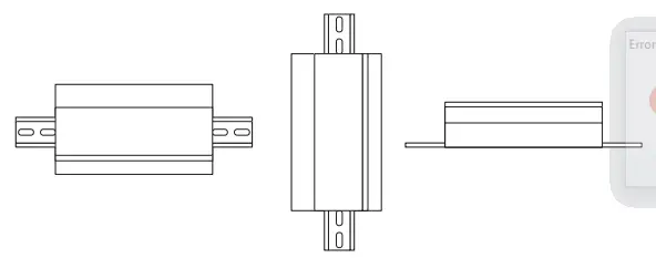
Installation types
Application area
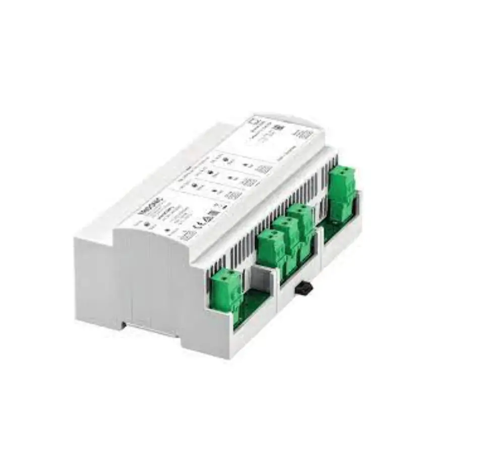
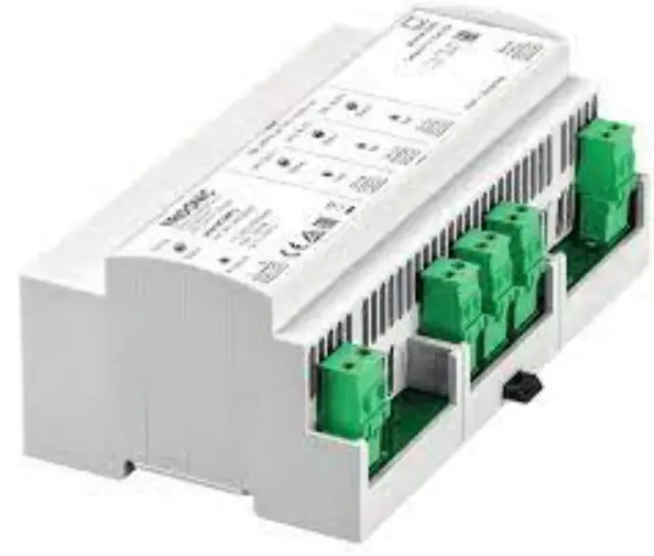
Control device with 3 DALI-compliant outputs for controlling a maximum of 192 luminaires
Technical data
| Nominal Voltage | 110-240 V.50-60 Hz |
| Permissible input voltage | 100-260 V. 50-60Hz |
| Power dissipation | Max.20W |
| Outputs | 3 DALI-compliant outputs (DALI BUS 1 – 3); per output: max. 64 DALI addresses; |
| Ports | 1 Ethernet port (Ethernet). RJ45 plug: speed of data transfer.10/100Mbif/s |
| Interface | Service Interface |
| Terminals | 05 – 25 mm’ (solid or fine-stranded) |
| Degree of protection | IP20 |
| Protection class | Pro1ect1on class II (only with correctly installed terminal covering) |
| Housing materials | Polycarbonate (PC),!lame-retardant, halogen-free |
| Installation | On top-hat rail35mm,naccordance with EN50022 |
| Dimensions | 160 x 91 x 62 CW x H x D. in mm),9 HP every 17.8 mm |
| Permissible ambient temperature | 0–50°C, installation type 1 (e.g. in distribution board) 0–40°C, installation types 2 and 3 |
| Permissible relative humidity | 20–90%, non-condensing |
| Weight | Approx. 600 a |
System design and installation notes
- Installation: fixed only, in a clean and dry environment, access only possible with tools; in solid distribution board or solid, closed distribution unit only, requirements given in standards for fire and contact safety must be met
- Topology: connect scene COM L and display device (touch panel, computer) via Ethernet cable (topology A) or connect scene COM L and display device (touch panel, computer, mobile device) via a wireless access point (topology B)
- Mains line: must not be interrupted by control points
- Ethernet line: at least CAT5 cable, shielded
- Bus line and DALI control line: use standard installation materials for low-voltage systems (< 1,000 V); only tree, linear and star topologies permitted
- Bus cores: may be reverse connected
- DALI control line:
| Conductor cross-section | Maximum DALI line length |
| 2 x 0,50 mm² | 100 m |
| 2 x 0,75 mm² | 150 m |
| 2 x 1,50 mm² | 300 m |
Function key
The function key can be Used to trigger certain function.
Triggering a function
- press the function key
- Release the function key in the desired orange phase
Function is triggered.
Orange phases (status LED device)
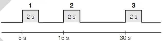
| Orange phase | Function |
| 1 | Restart the sceneCOM L. |
| 2 | Delete the addresses and short addresses of all control gear and input devices connected to the 3 DALI control lines. |
| 3 | Reset the IP address to the factory setting (10.10.40.254). |
Test key
The test key can be used to trigger tests and certain functions for the related output (DALI BUS 1 – 3).
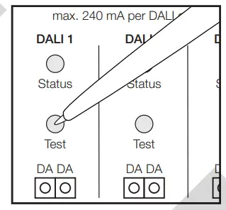
Triggering a function
- press the test key
- Release the test key in the desired orange phase.
Functions is triggered
Orange phases (status LED DALI BUS 1-3
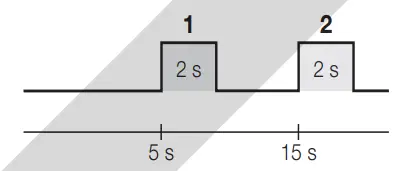
| Orange phase | Function |
| 1 | Exit test mode for all outputs. |
| 2 | Delete the addresses and short addresses of all control gear and input devices connected to the corresponding DALI control line. |
Test mode
- If the test key is pressed for less than 2 seconds, all connected luminaires are switched on.
- If the test key is then pressed again for less than 2 seconds, the luminaires alternate each time between on and off.
- To exit test mode, press the test key and release during the 1st orange phase
Status LED
Device
| Status LED | Duration | Description |
| Green, intermittently flickering | Continuous | Fault-free operation |
| Off | Continuous | No mains voltage (L, N) |
| DALI BUS 1 – 3 | ||
| Status LED | Duration | Fault-free operation |
| Green, intermittently flickering | Continuous | Fault-free operation |
| Green, flashing on/off every 0.5 s | Continuous | Test mode |
| Orange, flashing on/off every 0.5 s | Continuous | Addressing (Exception: visual and acoustic sensor location) or DALI initialization |
| Off | Continuous | No mains voltage (L, N) |
| Red | Continuous | More than 64 DALI-compliant devices connected |
| Red, intermittently flickering | Continuous | DALI control line short-circuited or more than 120 DALI loads |
| Red, interrupted by intermittent green flickering | Continuous | Lamp failure |
Safety instructions
- The device may only be used for the application area specified.
- Relevant health and safety regulations must be observed.
- When mounting and installing the device, the voltage supply must be disconnected.
- Only qualified personnel may mount, install and commission the device.
- Protection class II can only be guaranteed when the terminal covering has been correctly installed.
- If a fault occurs, dangerous voltage levels may be present at the DALI terminals and on the DALI control line.
Installation
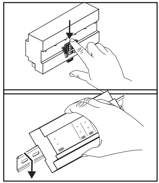
- Disconnect the voltage supply.
- Press the black locking hook down
Installation type 1 (e.g. in distribution board)
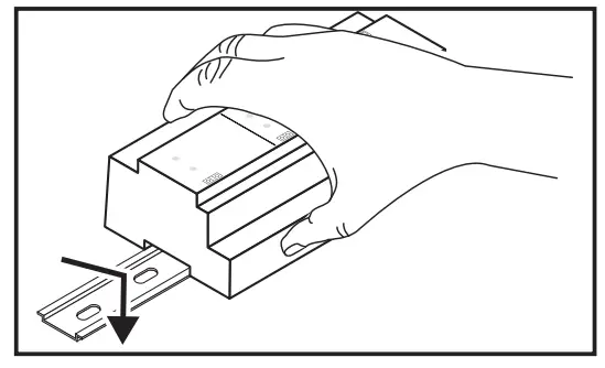
- First attach the top part and then the bottom part of the device to the top-hat rail
Installation type 2
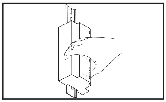
- First attach the top part and then the bottom part of the device to the top-hat rail.
Installation type 3
Depending on which side the black locking hook is situated:
- First attach the left part and then the right part of the device to the top-hat rail.
— or — - First attach the right part and then the left part of the device to the top-hat rail
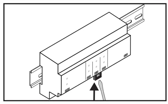
- Fasten the locking hook again.
- Reconnect the voltage supply
Initial steps after installation
Requirement:
- The scene COM L control device and display device (touch panel. computer) have been connected in accordance with topology A.
-or- - The sceneCOM L control device and display device (touch panel. computer. mobile device) have been connected in accordance with topology B.
- Ensure that the following settings are stored for the display device and the wireless access point:
– IP address . . ….. …….. 10.10.40.2 – 10.10.40.253
– Subnet mask. ………. . .. 255.255.0.0 - Open a browser (Google Chrome recommended).
- Go to the IP address of the sceneCOM L (10.10.40.254).
-+ The Tridonic system web application is displayed. - Run the installation test (see Test key – Test mode).
- Correct the installation faults.
- Commission the Tridonic system.
Note: Detailed information on commissioning and configuration can be found in the commissioning instructions.
For latest software versions please access our WEB page:
www.tridonic.com/software
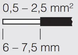
solid/fine-stranded


