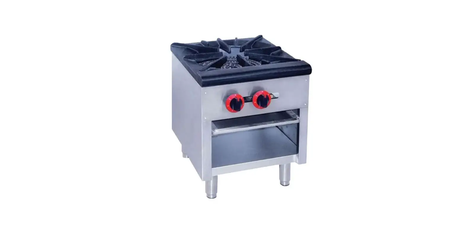
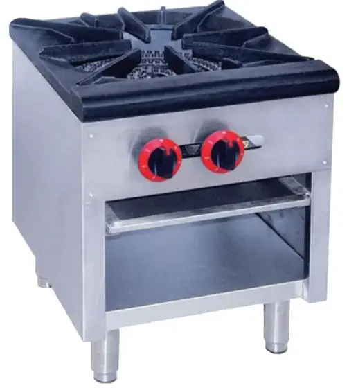
MOTAK MSP-1-N Burner Stock Pot Range Natural Gas
CONGRATULATIONS!
You have purchased one of the finest pieces of commercial cooking equipment on the market. You will find that your new equipment, like all MOTAK equipment, has been designed and manufactured to meet the toughest standards in the industry. Each piece of MOTAK equipment is carefully engineered and designs are verified through laboratory tests and field installations. With proper care and field maintenance, you will experience years of reliable, trouble-free operation. For best results, read this manual carefully.
SPECIFICATIONS
| DESCRIPTION | STOCK POT RANGE | |
| MODEL | MSP-1-N/ MSP-1-P | MSP-2-N/MSP-2-P |
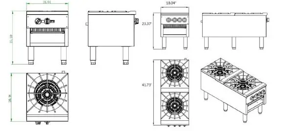
| DIMENSIONS | 18.4″ W X 21″D X 23.4″ H | 18.4″ W X 41.75″D X 23.4″ H |
| BTU PER BURNER | 40,000 | 40,000 |
| # OF BURNERS | 2 | 4 |
| TOTAL BTU’S | 80,000 | 160,000 |
| OPERATING GAS PRESSURE | NATURAL | L.P.G. |
| 4.0″ W.C. | 10″ W.C. | |
| ORIFICE SIZE | 3.15 mm | 1.95 mm |
| NET WEIGHT | 106 lbs. | 200 lbs. |
SAFETY PRECAUTIONS
To ensure safe operation read the follow statements and to understand their meaning. Please read carefully.
Warning: Warning is used to indicate the presence of a hazard that can cause severe personal injury, death or substantial property damage if the warning is ignored.
Caution: Caution is used to indicate the presence of a hazard that will or can cause minor personal injury or property damage if the caution is ignored.
Note: Note is used to notify people of installation, operation, or maintenance information that is important but not hazard-related. For Your Safety! These precautions should be followed at all times.
MUST READ
This manual contains important information regarding your MOTAK unit. Please read the manual thoroughly prior to equipment set-up and operation maintenance. Failure to comply with regular maintenance guidelines out-lined in the manual may void the warranty. Improper installation, adjustment, alteration, service or maintenance can cause property damage, injury or death. Read this manual thoroughly before installing or servicing this equipment.
FUNCTION & PURPOSE
This appliance is intended for commercial foodservice operations only. This is not intended for household, industrial or laboratory use.
UNPACKING THE EQUIPMENT
- Remove all packing material and tape as well as any protective plastic from the equipment. When no longer needed, dispose of all packaging and materials in an environmentally responsible manner.
- Use caution and assistance from others in lifting and moving the appliance.
- Clean any glue residue left over from the plastic tape.
- Place the appliance in the desired location.
- Install the four (4) legs (A) and feet (B) on the appliance. (See Figure 1 on next page.)
- Before using this appliance, it must be cleaned and dried thoroughly.
NOTE: It is vital that the purchaser of this appliance post this information in a prominent location. Instructions are to be followed in the event that the user smells gas. This information shall be obtained by consulting the local gas supplier.
INSTALLATION
The installation of this equipment must conform with local codes, or with the National Gas Code, ANSIZ223.1/NFPA 54, or the Natural Gas and Propane Installation Code, CSA B149.1, as applicable.
- The appliance and its individual shutoff valve must be disconnected from the gas supply piping system during any pressure testing of that system at test pressures in excess of ½ P.S.I. (3.5kPa).
- The appliance must be isolated from the gas supply piping system by closing its individual manual shutoff valve (supplied by others), during any pressure testing of the gas supply piping system at test pressures equal to or less than ½ P.S.I. (3.5kPa)
WARNING
- Do not store or use gasoline or other flammable vapors or liquids in the vicinity of this or any other equipment.
- Improper installation, adjustment, alteration, service or maintenance can cause property damage, injury or death.
- Read the installation and maintenance instructions thoroughly before installing or servicing this equipment.
- Have the equipment installed by a qualified installer in accordance with all federal, state and local codes.
- Do not install or use without all 8” legs.
- Do not obstruct the flow of combustion and ventilation air.
- Do not spray controls or the outside of the equipment with liquids or cleaning agents
- Allow for hot parts to cool before cleaning or moving.
- This equipment should only be used in a flat, level position.
- Do not operate unattended.
- Any loose dirt or metal particles that are allowed to enter the gas lines on this equipment will damage the valve and affect its operation.
- If you smell gas, follow the instructions provided by the gas supplier. Do not try to light the burner; do not use a telephone within close proximity.
- Never attempt to move grate while cooking.
FIRE, INJURY OR DEATH HAZARD
This appliance must be installed and adjusted by a qualified technician in accordance with all federal, state, and local codes. Failure to install, adjust or maintain this equipment properly can result in Fire, Injury or Death. Read theinstallation/operating/maintenance instructions thoroughly before install or service of this appliance. FOR YOUR SAFETY Do not store or use gasoline or other flammable vapors or liquids in the vicinity of this or any other appliance. WARNING FIRE HAZARD – Do not install or use without the eight-inch (8”) legs. Use of this equipment without legs can cause the appliance to overheat and cause fire.
Clearance and Positioning Around the Appliance: This equipment must be installed with a six-inch (6”) clearance from sides and rear from combustible material. Zero (0) clearance from non-combustible. For use on a non-combustible floor.
Air Supply and Ventilation: The area in front and around the equipment must be kept clear to avoid any obstruction of the flow of combustion and ventilation air. Adequate clearance must be maintained at all times in front of and at the sides of the appliance for servicing and proper ventilation.
Pressure Regulator: This commercial appliance comes with a convertible pressure regulator to insure proper and efficient operation. The pressure regulator provided is adaptable for both Natural and LPG gas. Regulator specifications: ¾” NPT inlet and outlet, preset for four-inches (4”) WC Natural Gas and may be converted by qualified personnel to be used for LPG at ten-inches (10”) WC.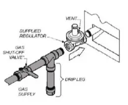
Prior to connecting the regulator, check the incoming line pressure. The regulator can only withstand a maximum pressure of ½” PSI (13” WC). If the line pressure is beyond this limit, a step-down regulator before the appliance regulator provided will be required. The arrow on the bottom of the appliance regulator shows the gas flow direction and should point downstream to the equipment.
LIGHTING THE PILOT
The appliance is equipped with standing pilots and each should be lit immediately after the gas is supplied to the equipment.
- Before attempting to light the pilots, turn off the main gas valve to the equipment and wait 5 minutes to clear the gas.
- Turn off all gas control knobs.
- Light all pilots manually with ignition source.
- The pilot burner must be lit at the end of the tube. Hold an ignition source through the pilot light hole in the front panel at the pilot tube. When the flame ignites remove ignition source.
- Turn off the main gas valve to shut down the equipment.
Smoke appearing on initial use of the appliance is normal. This is a result of the rust preventative coating burning off. Allow the equipment to “burn in” for at least 15 minutes before the first use.
PILOT FLAME REGULATION:
The pilot flame on the appliance has been factory adjusted. When adjustment is necessary, adjust the pilot flame as small as possible but high enough to light the burner immediately with the burner valve is turned to the highest setting. Access to the pilot flame adjustment screw is through the opening in the front panel. (See “D” in the diagram below)
BURNER FLAME AIR ADJUSTMENT:
Remove the front panel (D), to gain access. Turn the burner knob (E) to the highest setting. You should see a blue flame that is not lifting or have yellow tipping. If this occurs, loosen the air shutter screw on the burner’s air shutter and turn air shutter to obtain correct flame. (This can only be obtained if the gas pressure is correct.
Features and Controls: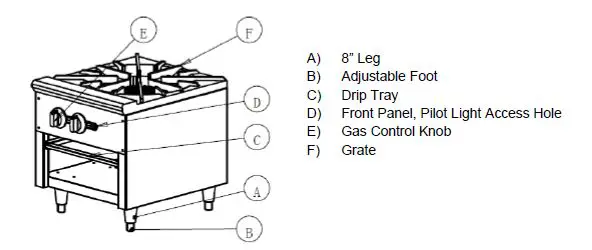
OPERATION
Before initial use, turn the gas control knob to the maximum setting and allow the appliance to “burn-in” for approximately fifteen (15) minutes. Seeing smoke coming from the cooking grate is normal during burn-in period. After about fifteen (15) minutes of burn-in the appliance is ready for use.
- With the use of a spirit level, check for level front to back, left to right, and diagonally. Adjust leveling feet as needed.
- Check the drip tray frequently.
- To ignite the burner, depress and turn the gas control knob to high position.
- Adjust the valve set-point to obtain the desired level of heat.
CLEANING:
To maintain the appearance and increase the service life, clean your appliance daily. DO NOT clean appliance with steel wool.
- Allow the appliance to cool completely before cleaning.
- Using a wire brush, scrape the burner grate to remove any food or cooking residue.
- To clean equipment, use either a damp cloth, sponge with soapy water. Use of a metal scrapper may be necessary for heavy burnt-on residue.
- Dry cooking grates thoroughly to prevent rusting.
- Empty and clean drip tray.
Maintenance:
- A qualified service company should check the unit for safe and efficient operation on an annual basis.
- Gas piping shall be a certain size and installed to provide a supply of gas sufficient to meet the full gas input of the appliance.
- A manual shut off valve should be installed upstream from the manifold within four (4) feet of the appliance and in a position with it can be reached in the event of an emergency.
- Check entire gas piping system for leaks periodically. Using a gas leak detector or soapy water solution is recommenced. DO NOT USE OPEN FLAME!
- Install equipment under efficient exhaust hood with flameproof filters with a distance of no less than four (4) feet between the top of the equipment and the filters or any other combustible materials.
PARTS LISTS FOR IRSP-1B
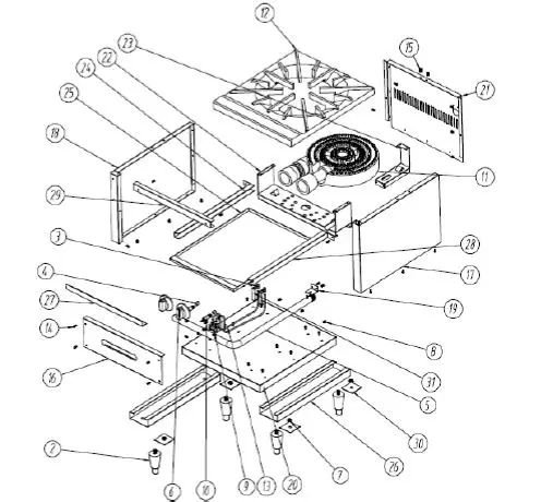
| Ref # | Part # | Description | Qty | Ref # | Part # | Description | Qty | |
| 1 | SPIR10010 | Knob | 2 | 16 | SP10021 | Front control panel | 1 | |
| 2 | SP10001 | Adjustable foot | 4 | 17 | N/A | Right cover board | 1 | |
| 3 | GC10003 | Pilot | 2 | 18 | N/A | Left cover board | 1 | |
| 4 | SP10001.95 | Orifice LPG (1.95 mm) | 2 | 19 | N/A | Mounting Bracket for Manifold | 1 | |
| 4 | SP10003.15 | Orifice NAT (3.15 mm) | *2 | 20 | N/A | Base Channel | 1 | |
| 5 | N/A | Gas inlet tube | 1 | 21 | N/A | Back Channel | 1 | |
| 6 | NA | Testing end cap for inlet pipe | 1 | 22 | SP10023 | Supporting plate for burner | 1 | |
| 7 | NA | M12 nut | 4 | 23 | N/A | Connecting plate | 1 | |
| 8 | NA | M5-10 hexagonal bolt | 3 | 24 | N/A | Left rail | 1 | |
| 9 | GR10018 | Pilot Adjustment valve | 1 | 25 | SP10022 | Crumb Tray | 1 | |
| 10 | GC10004 | Gas valve | 2 | 26 | N/A | Stiffening plate for foot | 2 | |
| 11 | SP10020 | Cast Iron Burner | 1 | 27 | N/A | Supporting plate for inlet tube | 1 | |
| 12 | SP10011 | Cast Iron Burner Grate | 1 | 28 | N/A | Right rail | 1 | |
| 13 | N/A | Tube connecting to pilot | 2 | 29 | N/A | Stiffening plate | 1 | |
| 14 | N/A | Round head screw (M4-12) | 36 | 30 | N/A | Support for foot | 4 | |
| 15 | N/A | Flat head screw (M8-12) | 3 | 31 | N/A | Mounting Bracket for Pilot | 2 |
PARTS LISTS FOR IRSP-2B
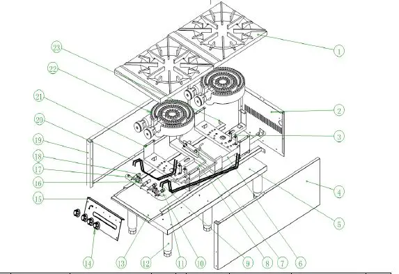
| Ref # | Part # | DESCRIPTION | Qty | Ref # | Part # | DESCRIPTION | Qty | |
| 1 | SP10011 | Burner Grate | 2 | 13 | SP10017 | Crumb Tray | 1 | |
| 2 | NA | Rear Shroud | 1 | 14 | SPIR10010 | Knob | 4 | |
| 3 | GC10003 | Pilot | 4 | 15 | SP10018 | Front Panel | 1 | |
| 4 | NA | Right Side Panel | 1 | 16 | GR10018 | Adjustable valve | 2 | |
| 5 | N/A | Baseboard | 1 | 17 | GC10004 | Gas Valve | 4 | |
| 6 | NA | Gas Inlet Pipe | 1 | 18 | SP10001.95 | LPG Orifice Fitting (1.95 mm) | 8 | |
| 7 | SP10012 | Connector (Nozzel) | 2 | 18 | SP10003.15 | NAT Orifice Fitting (3.15 mm) | 8 | |
| 8 | SP10013 | Connecting Pipe (Burner) | 2 | 19 | NA | Left Side Panel | 1 | |
| 9 | SP10014 | Connecting Pipe A (Pilot) | 2 | 20 | SP10019 | Connecting Pipe B (Pilot) | 2 | |
| 10 | SP10015 | Connector (Gas Valve) | 2 | 21 | NA | Supporting Plate (Burner) | 2 | |
| 11 | NA | Guide Rail (Right) | 1 | 22 | SP10020 | Burner | 2 | |
| 12 | SP10001 | Adjustable Leg | 6 | 23 | NA | Guide Rail (Left) | 1 |
A product with the MOTAK name incorporates the best in durability and low maintenance. We all recognize, however, that replacement parts and occasional professional service may be necessary to extend the useful life of this unit. When service is needed, contact an MOTAK Authorized Service Provider, or your equipment dealer. To avoid confusion, always refer to the model number, serial number and the gas type of your unit. Thank You!


